Holden Colorado (RG; 2013 – 2016) – fuse and relay box diagram
Year of production: 2013, 2014, 2015, 2016
This article provides the second-generation Holden Colorado (RG, pre-facelift), manufactured from 2012 to 2016. It includes fuse box diagrams for the 2013, 2014, 2015, and 2016 models, along with details on the location of the fuse panels inside the vehicle and the specific functions of each fuse (fuse layout).
Passenger Compartment Fuse Box
Fuse Box Location
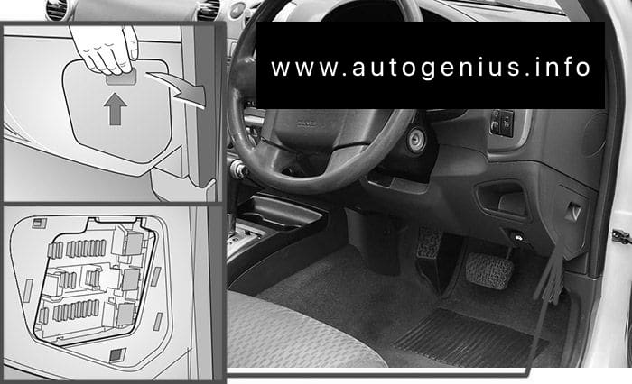
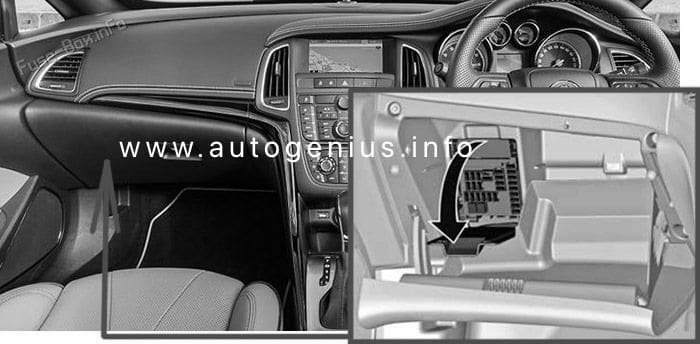
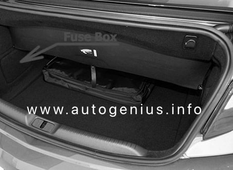
The fuse box is in a storage compartment on the driver’s side of the instrument panel.
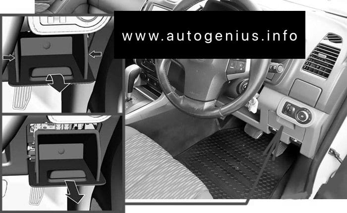
- Press the sides of the storage compartment inwards.
- Lift the storage compartment until it audibly disengages.
- Remove by pulling rearwards.
- Reinstall in the reverse order.
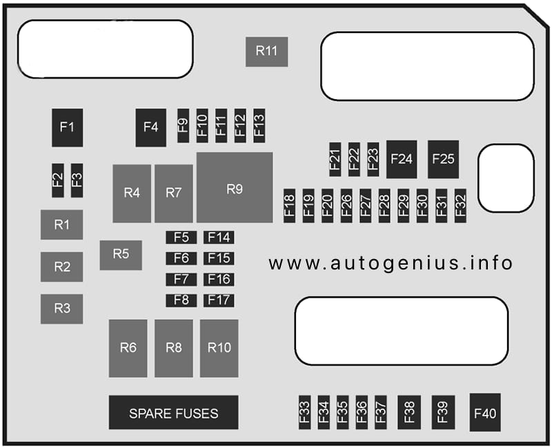
Fuse Box Diagram
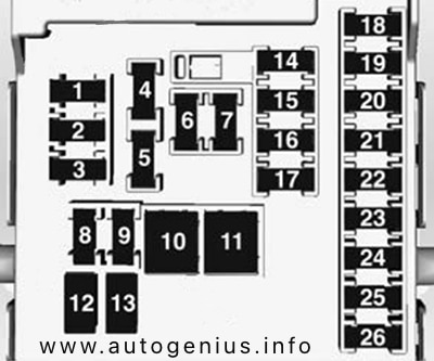
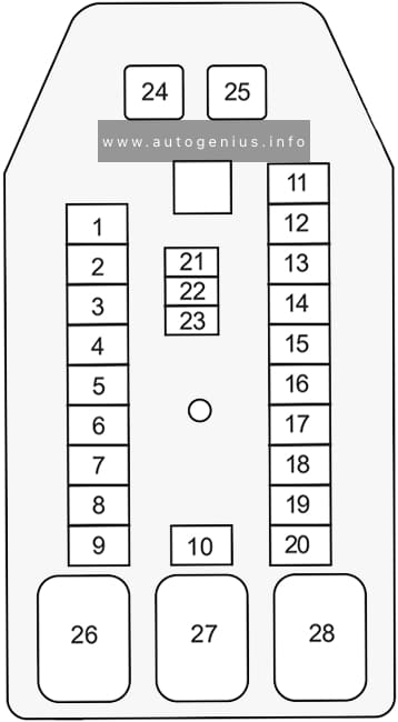
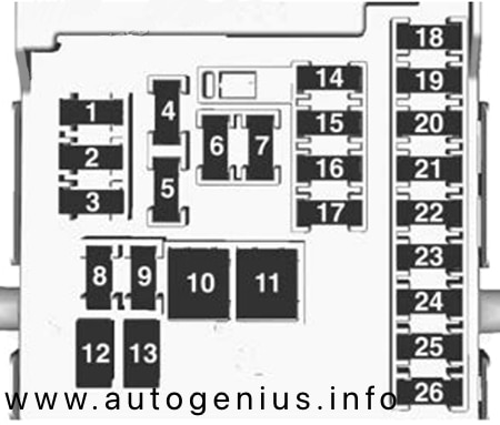
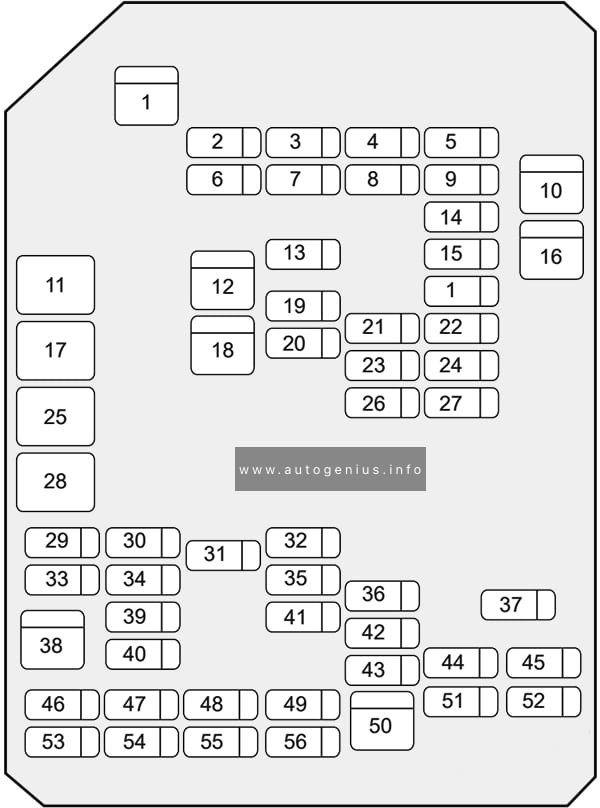
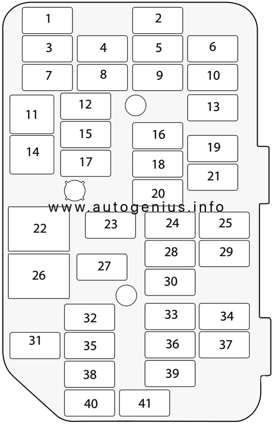
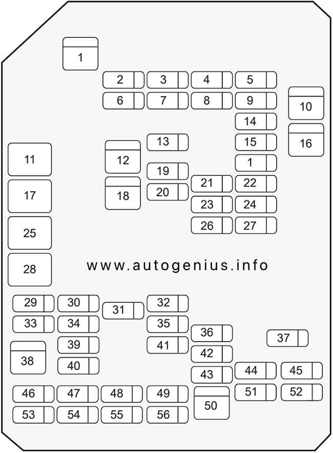
Assignment of the fuses in the passenger compartment (instrument panel)
| № | Amps | Description |
|---|---|---|
| 1 | 15A | HVAC AUTO |
| 2 | 15A | BODY CONTROL MODULE (6) |
| 3 | 15A | BODY CONTROL MODULE (5) |
| 4 | 20A | CIGAR LIGHTER AND POWER OUTLET |
| 5 | 2A | CLOCK SPRING |
| 6 | 30A | POWER WINDOW |
| 7 | 20A | POWER OUTLET |
| 8 | 15A | BODY CONTROL MODULE (2) |
| 9 | 15A | BODY CONTROL MODULE (4) |
| 10 | 30A | BODY CONTROL MODULE (8) |
| 11 | 40A | RAP & ACCESSORY 12V |
| 12 | – | – |
| 13 | – | – |
| 14 | 7.5A | DATA LINK CONNECTOR (DLC) |
| 15 | 10A | SENSING AND DIAGNOSTIC MODULE (SDM) |
| 16 | 10A | INSTRUMENT PANEL CLUSTER (IPC) |
| 17 | 20A | RADIO |
| 18 | 30A | HVAC BLOWER |
| 19 | 5A | OUTSIDE REAR VIEW MIRRORS |
| 20 | – | |
| 21 | 10A | HVAC CONTROL HEAD |
| 22 | 2A | IGNITION SWITCH |
| 23 | 15A | BODY CONTROL MODULE (5) |
| 24 | 15A | BODY CONTROL MODULE (3) |
| 25 | 20A | POWER WINDOW SWITCH |
| 26 | 25A | POWER SEAT |
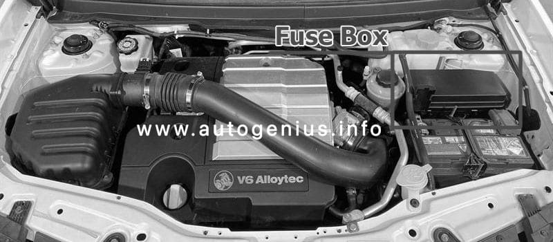
Engine Compartment Fuse Box
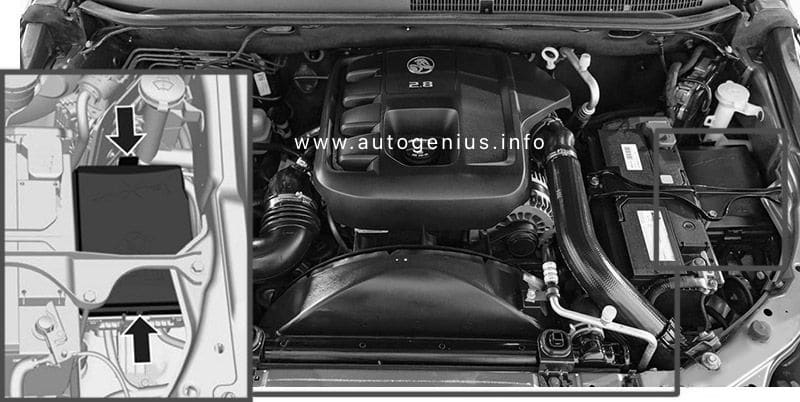
Fuse Box Location
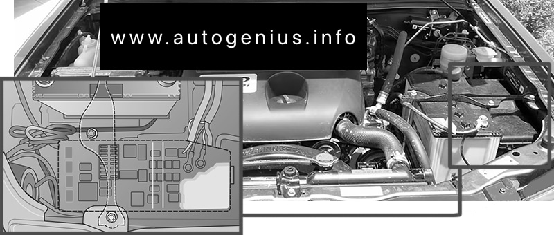
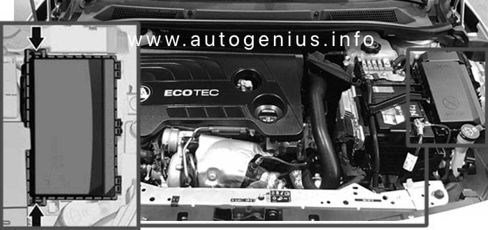
The fuse box is located on the passenger’s side of the engine compartment. To disengage the cover, lift upwards and remove.
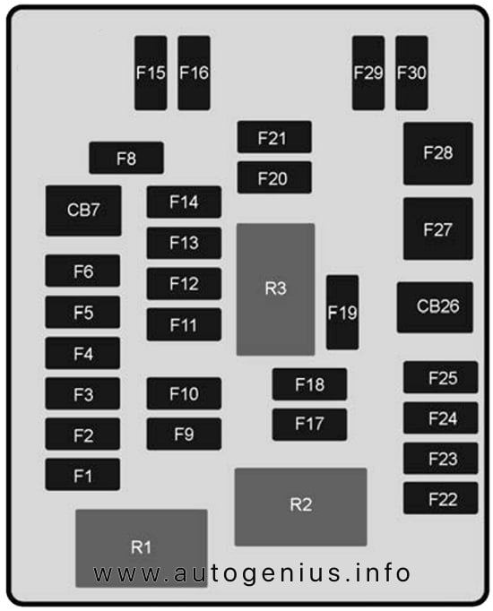
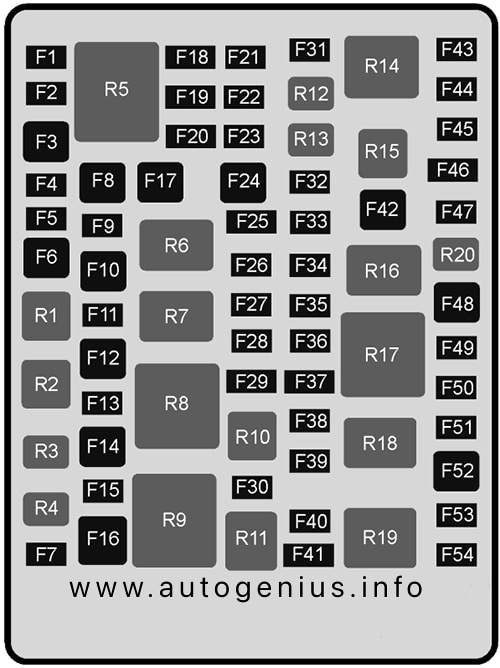
Fuse Box Diagram
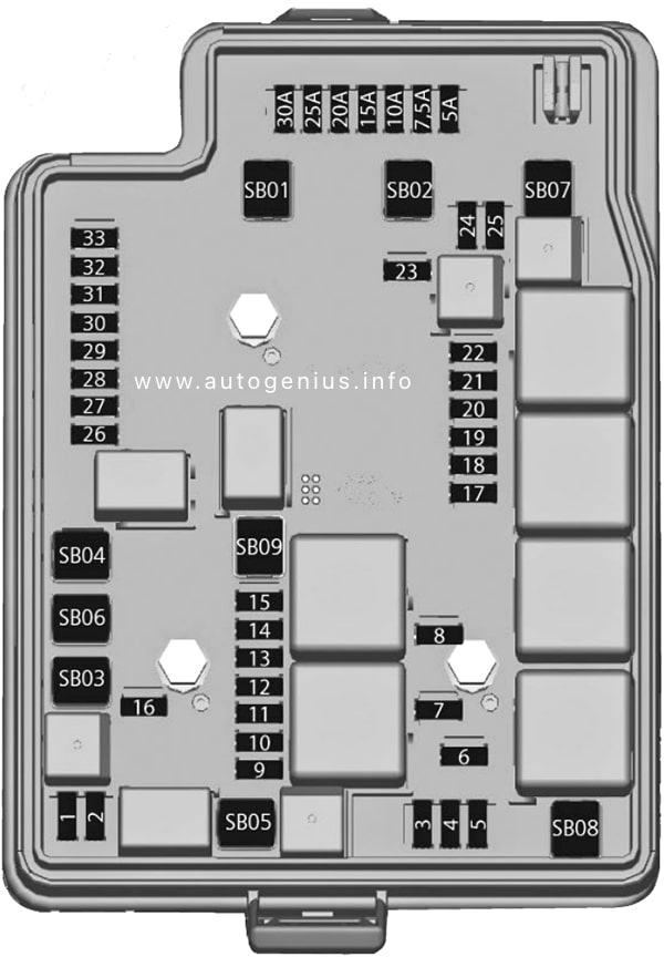
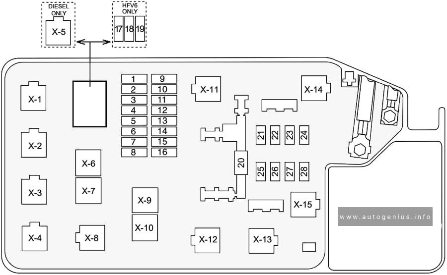
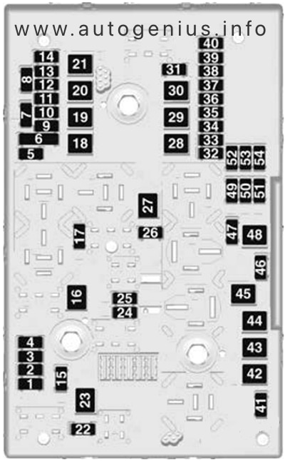
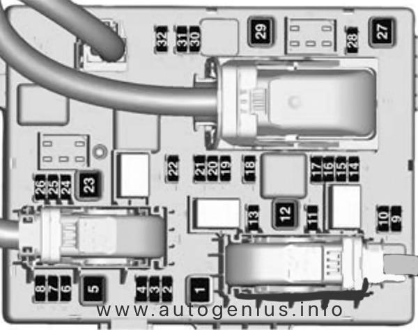
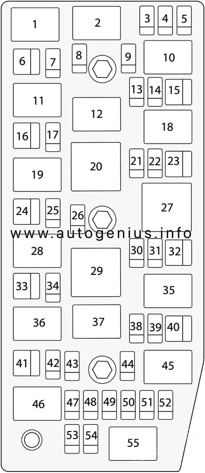
Assignment of the fuses in the engine compartment
| № | Amps | Description |
|---|---|---|
| 1 | 10A | COMPRESSOR A/C CLUTCH |
| 2 | 15A | BCM BATT 6 |
| 3 | 15A | SPARE |
| 4 | 10A | REAR LATCH |
| 5 | 15A | HORN |
| 6 | 15A | FRONT FOG LAMP |
| 7 | 10A | HIGH BEAM LH |
| 8 | 10A | HIGH BEAM RH |
| 9 | 10A | 2016: ENGINE CONTROL MODULE |
| 10 | 15A | ENGINE 3 |
| 11 | 20A | ENGINE CONTROL MODULE1 |
| 12 | 10A | ENGINE 1 |
| 13 | 10A | ENGINE 2 |
| 14 | 15A | ENGINE 4 |
| 15 | 15A | PWT |
| 16 | 15A | TCM |
| 17 | 10A | TRANSFER CASE MODULE AND LAMP LEVELLING |
| 18 | 10A | CLUSTER – A/C – SDM |
| 19 | 20A | FUEL PUMP |
| 20 | 5A | SPARE |
| 21 | 30A | REAR WINDOW HEATER |
| 22 | 15A | OUTSIDE REAR VIEW MIRROR |
| 23 | 15A | VISCOUS HEATER |
| 24 | 20A | REAR WIPER |
| 25 | 10A | FRT WASHER |
| 26 | 10A | REAR PARK ASSIST |
| 27 | 5A | BODY CONTROL MODULE RVC |
| 28 | 7.5A | DRL / COLD START |
| 29 | 30A | ABS MODULE ESC1 |
| 30 | 10A | 2013-2014: CONTENT THEFT RELAY 2015-2016: HORN |
| 31 | 15A | BODY CONTROL MODULE BATT 7 |
| 32 | 15A | ENGINE CONTROL MODULE |
| 33 | 10A | COMMON ENABLE |
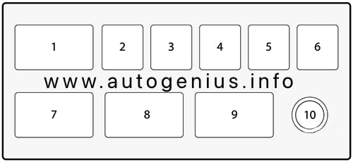
| SB01 | 50A | ABS MODULE PUMP |
| SB02 | 30A | TRANSFER CASE CONTROL MODULE (4X4) |
| SB03 | 60A | GLOW PLUG MODULE (DIESEL) |
| SB04 | 20A | SPARE |
| SB05 | 30A | STARTER MOTOR SOLENOID |
| SB06 | 30A | FRONT WIPER |
| SB07 | 30A | COOL FAN |
| SB08 | – | – |
| SB09 | 30A | SPARE |
WARNING: Terminal and harness assignments for individual connectors will vary depending on vehicle equipment level, model, and market.