Chrysler LHS (1993 – 1997) – fuse box diagram

Chrysler LHS (1993 – 1997) – fuse box diagram

Year of production: 1993, 1994, 1995, 1996, 1997

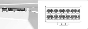
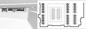
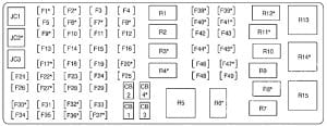
Passenger compartment fuse box

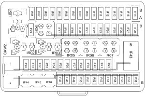
Chrysler LHS - fuse box diagram - passenger compartment
Chrysler LHS – fuse box diagram – passenger compartment
Chrysler LHS - fuse box diagram - passenger compartment fuse box
Chrysler LHS – fuse box diagram – passenger compartment fuse box

A
Protected Component
1 5 Heated Power Mirrors
2 10 Radio
3 10 Right & Left Turn Signals
4 20 Stoplights
5 5 Headlight Delay Sense
6 10 Climate Control, Rear Window Defrost, Back-Up Lights, ABS Module, Daytime Running Lights, Speed Proportional Steering
7 10 Air Bag Module
8 20 Horns, Horn Relay, Cigarette Lighter, Radio Amplifier
9 15 Taillights, License & Parking Lights, Illumination Lights, Radio
10 10 Wiper Motor Relay, Washer Motor
11 15 Left High Beam Headlight
12 15 Right High Beam Headlight, High Beam Indicator
13 10 Body Controller, Door Lock Switches, Instrument Panel Connector, Radio Memory, Power Mirrors, Trunk Release, Remote Keyless Entry, Message Center, ATC Aspirator Motor, Lights: Rear Reading, Map, Glove Box, Key-In, Vanity Mirror, Underhood, Trunk, Door & Front Courtesy
14 5 Body Controller, Message Center, Speed Control Relay (’93-’95), Power Window Switch, Door Lock Switch Light, Power Mirrors, Overhead Console, Remote Keyless Entry, Sunroof Control Module
15 15 Left Low Beam
16 15 Right Low Beam, Foglights
17 5 Auto Trans Controller, Body Controller, Gear Selector Indicator
18 10 Engine Controller, Fuel Pump Relay, ASD Relay
19 10 Air Bag Module
20 10 Oxygen Sensor, Fan Relay, Purge Solenoid, EGR Solenoid, A/C Relay, Fan Relays, Manifold Solenoid
21 25 Blower Motor
22 20 Circuit Breaker: Power Window Motors, Power Window Switch Lights
23 20 Circuit Breaker: Power Door Lock Motors, Power Seats, Power Antenna, Sunroof Control Module
Relay
R1 Door Unlock
R2 Door Lock
R3 Horn
R4  –
R5 Headlamp Delay

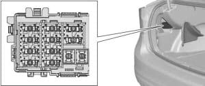
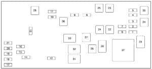
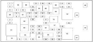
Engine compartment

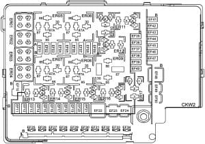
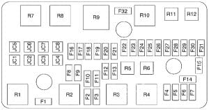
Chrysler LHS - fuse box diagram - engine comaprtment
Chrysler LHS – fuse box diagram – engine comaprtment
Chrysler LHS - fuse box diagram - engine comaprtment fuse box
Chrysler LHS – fuse box diagram – engine comaprtment fuse box

A
Protected Component
A 20 ’94-’97: Ignition Switch, Starter Relay, Fuel Pump Relay
20 ’93: Powertrain Control Module (PCM), Automatic Shut Down Relay, Transmission Relay, Transmission Control Module (TCM)
B 20 ’94-’97: Powertrain Control Module (PCM), Automatic Shut Down Relay, Transmission Relay, Transmission Control Module (TCM)
20 ’93: Ignition Switch
C 40 ’94-’97: ABS Pump Motor Relay
30 ’93: Intermmitent Wiper Relay
D 40 High Speed Radiator Fan Relay, Low Speed Radiator Fan, A/C Compressor Clutch Relay
E 30 ’94-’97: Intermmitent Wiper Relay
30 ’93: Headlamp Switch, Headlamp Dimmer Switch, Headlamp Delay Relay, Fuse No.: “L”; Circuit Breaker: “23”
F 20 ’94-’97: Fuse No.: “8”, “9”
40 ’93: ABS Motor Relay
G 20 ’94-’97: Fuse No.: “4”, “13”
40 ’93: Ignition Switch
H 30 ’94-’97: Headlamp Switch, Headlamp Dimmer Switch, Headlamp Delay Relay, Fuse No.: “L”; Circuit Breaker: “23”
30 ’93: ABS Main Relay, ABS Control Module
I 30 ’94-’97: ABS Main Relay, ABS Control Module
20 ’93: Fuse No.: “8”, “9”
J 40 ’94-’97: Ignition Switch
20 ’93: Fuse No.: “4”, “13”
K 20 Combination Flasher (Hazard Warning Light)
L 10 Daytime Running Lamp Module
M  –
Relay
R1 High Speed Radiator Fan
R2 Low Speed Radiator Fan
R3 A/C Compressor Clutch
R4 Automatic Shut Down
R5 Fuel Pump
R6 Intermmitent Wiper
R7  –
R8 Starter
R9 Transmission
R10 Wiper (High/Low Speed)
R11 ABS Main
R12 ABS Pump Motor


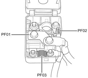
Fusible Link

  1. WHT (22 Ga) – Fuse No.: “K” (Combination Flasher)
  2. BRN (18 Ga) – A/C Heater Control (Manual A/C) / Automatic Temp Control Module (Auto A/C)
  3. BLK (12 Ga) – Alternator

WARNING: Terminal and harness assignments for individual connectors will vary depending on vehicle equipment level, model, and market.

Chrysler Concorde (1993 – 1997) – fuse box diagram

Chrysler Concorde (1993 – 1997) – fuse box diagram

Year of production: 1993, 1994, 1995, 1996, 1997

Passenger compartment fuse box

Chrysler Concorde - fuse box diagram - passenger compartment
Chrysler Concorde – fuse box diagram – passenger compartment
Chrysler Concorde - fuse box diagram - passenger compartment fuse box
Chrysler Concorde – fuse box diagram – passenger compartment fuse box

A
Protected Component
1 5 Heated Power Mirrors
2 10 Radio
3 10 Right & Left Turn Signals
4 20 Stoplights
5 5 Headlight Delay Sense
6 10 Climate Control, Rear Window Defrost, Back-Up Lights, ABS Module, Daytime Running Lights, Speed Proportional Steering
7 10 Air Bag Module
8 20 Horns, Horn Relay, Cigarette Lighter, Radio Amplifier
9 15 Taillights, License & Parking Lights, Illumination Lights, Radio
10 10 Wiper Motor Relay, Washer Motor
11 15 Left High Beam Headlight
12 15 Right High Beam Headlight, High Beam Indicator
13 10 Body Controller, Door Lock Switches, Instrument Panel Connector, Radio Memory, Power Mirrors, Trunk Release, Remote Keyless Entry, Message Center, ATC Aspirator Motor, Lights: Rear Reading, Map, Glove Box, Key-In, Vanity Mirror, Underhood, Trunk, Door & Front Courtesy
14 5 Body Controller, Message Center, Speed Control Relay (’93-’95), Power Window Switch, Door Lock Switch Light, Power Mirrors, Overhead Console, Remote Keyless Entry, Sunroof Control Module
15 15 Left Low Beam
16 15 Right Low Beam, Foglights
17 5 Auto Trans Controller, Body Controller, Gear Selector Indicator
18 10 Engine Controller, Fuel Pump Relay, ASD Relay
19 10 Air Bag Module
20 10 Oxygen Sensor, Fan Relay, Purge Solenoid, EGR Solenoid, A/C Relay, Fan Relays, Manifold Solenoid
21 25 Blower Motor
22 20 Circuit Breaker: Power Window Motors, Power Window Switch Lights
23 20 Circuit Breaker: Power Door Lock Motors, Power Seats, Power Antenna, Sunroof Control Module
Relay
R1 Door Unlock
R2 Door Lock
R3 Horn
R4  –
R5 Headlamp Delay

Engine compartment

Chrysler Concorde - fuse box diagram - engine comaprtment
Chrysler Concorde – fuse box diagram – engine comaprtment
Chrysler Concorde - fuse box diagram - engine comaprtment fuse box
Chrysler Concorde – fuse box diagram – engine comaprtment fuse box

A
Protected Component
A 20 ’94-’97: Ignition Switch, Starter Relay, Fuel Pump Relay
20 ’93: Powertrain Control Module (PCM), Automatic Shut Down Relay, Transmission Relay, Transmission Control Module (TCM)
B 20 ’94-’97: Powertrain Control Module (PCM), Automatic Shut Down Relay, Transmission Relay, Transmission Control Module (TCM)
20 ’93: Ignition Switch
C 40 ’94-’97: ABS Pump Motor Relay
30 ’93: Intermmitent Wiper Relay
D 40 High Speed Radiator Fan Relay, Low Speed Radiator Fan, A/C Compressor Clutch Relay
E 30 ’94-’97: Intermmitent Wiper Relay
30 ’93: Headlamp Switch, Headlamp Dimmer Switch, Headlamp Delay Relay, Fuse No.: “L”; Circuit Breaker: “23”
F 20 ’94-’97: Fuse No.: “8”, “9”
40 ’93: ABS Motor Relay
G 20 ’94-’97: Fuse No.: “4”, “13”
40 ’93: Ignition Switch
H 30 ’94-’97: Headlamp Switch, Headlamp Dimmer Switch, Headlamp Delay Relay, Fuse No.: “L”; Circuit Breaker: “23”
30 ’93: ABS Main Relay, ABS Control Module
I 30 ’94-’97: ABS Main Relay, ABS Control Module
20 ’93: Fuse No.: “8”, “9”
J 40 ’94-’97: Ignition Switch
20 ’93: Fuse No.: “4”, “13”
K 20 Combination Flasher (Hazard Warning Light)
L 10 Daytime Running Lamp Module
M  –
Relay
R1 High Speed Radiator Fan
R2 Low Speed Radiator Fan
R3 A/C Compressor Clutch
R4 Automatic Shut Down
R5 Fuel Pump
R6 Intermmitent Wiper
R7  –
R8 Starter
R9 Transmission
R10 Wiper (High/Low Speed)
R11 ABS Main
R12 ABS Pump Motor


Fusible Link

  1. WHT (22 Ga) – Fuse No.: “K” (Combination Flasher)
  2. BRN (18 Ga) – A/C Heater Control (Manual A/C) / Automatic Temp Control Module (Auto A/C)
  3. BLK (12 Ga) – Alternator

WARNING: Terminal and harness assignments for individual connectors will vary depending on vehicle equipment level, model, and market.

Dodge Intrepid (1993 – 1997) – fuse box diagram

Dodge Intrepid (1993 – 1997) – fuse box diagram

Year of production: 1993, 1994, 1995, 1996, 1997

Passenger compartment fuse box

Dodge Intrepid - fuse box diagram - passenger compartment
Dodge Intrepid – fuse box diagram – passenger compartment
Dodge Intrepid - fuse box diagram - passenger compartment fuse box
Dodge Intrepid – fuse box diagram – passenger compartment fuse box

A
Protected Component
1 5 Heated Power Mirrors
2 10 Radio
3 10 Right & Left Turn Signals
4 20 Stoplights
5 5 Headlight Delay Sense
6 10 Climate Control, Rear Window Defrost, Back-Up Lights, ABS Module, Daytime Running Lights, Speed Proportional Steering
7 10 Air Bag Module
8 20 Horns, Horn Relay, Cigarette Lighter, Radio Amplifier
9 15 Taillights, License & Parking Lights, Illumination Lights, Radio
10 10 Wiper Motor Relay, Washer Motor
11 15 Left High Beam Headlight
12 15 Right High Beam Headlight, High Beam Indicator
13 10 Body Controller, Door Lock Switches, Instrument Panel Connector, Radio Memory, Power Mirrors, Trunk Release, Remote Keyless Entry, Message Center, ATC Aspirator Motor, Lights: Rear Reading, Map, Glove Box, Key-In, Vanity Mirror, Underhood, Trunk, Door & Front Courtesy
14 5 Body Controller, Message Center, Speed Control Relay (’93-’95), Power Window Switch, Door Lock Switch Light, Power Mirrors, Overhead Console, Remote Keyless Entry, Sunroof Control Module
15 15 Left Low Beam
16 15 Right Low Beam, Foglights
17 5 Auto Trans Controller, Body Controller, Gear Selector Indicator
18 10 Engine Controller, Fuel Pump Relay, ASD Relay
19 10 Air Bag Module
20 10 Oxygen Sensor, Fan Relay, Purge Solenoid, EGR Solenoid, A/C Relay, Fan Relays, Manifold Solenoid
21 25 Blower Motor
22 20 Circuit Breaker: Power Window Motors, Power Window Switch Lights
23 20 Circuit Breaker: Power Door Lock Motors, Power Seats, Power Antenna, Sunroof Control Module
Relay
R1 Door Unlock
R2 Door Lock
R3 Horn
R4  –
R5 Headlamp Delay

Engine compartment

Dodge Intrepid - fuse box diagram - engine comaprtment
Dodge Intrepid – fuse box diagram – engine comaprtment
Dodge Intrepid - fuse box diagram - engine comaprtment fuse box
Dodge Intrepid – fuse box diagram – engine comaprtment fuse box

A
Protected Component
A 20 ’94-’97: Ignition Switch, Starter Relay, Fuel Pump Relay
20 ’93: Powertrain Control Module (PCM), Automatic Shut Down Relay, Transmission Relay, Transmission Control Module (TCM)
B 20 ’94-’97: Powertrain Control Module (PCM), Automatic Shut Down Relay, Transmission Relay, Transmission Control Module (TCM)
20 ’93: Ignition Switch
C 40 ’94-’97: ABS Pump Motor Relay
30 ’93: Intermmitent Wiper Relay
D 40 High Speed Radiator Fan Relay, Low Speed Radiator Fan, A/C Compressor Clutch Relay
E 30 ’94-’97: Intermmitent Wiper Relay
30 ’93: Headlamp Switch, Headlamp Dimmer Switch, Headlamp Delay Relay, Fuse No.: “L”; Circuit Breaker: “23”
F 20 ’94-’97: Fuse No.: “8”, “9”
40 ’93: ABS Motor Relay
G 20 ’94-’97: Fuse No.: “4”, “13”
40 ’93: Ignition Switch
H 30 ’94-’97: Headlamp Switch, Headlamp Dimmer Switch, Headlamp Delay Relay, Fuse No.: “L”; Circuit Breaker: “23”
30 ’93: ABS Main Relay, ABS Control Module
I 30 ’94-’97: ABS Main Relay, ABS Control Module
20 ’93: Fuse No.: “8”, “9”
J 40 ’94-’97: Ignition Switch
20 ’93: Fuse No.: “4”, “13”
K 20 Combination Flasher (Hazard Warning Light)
L 10 Daytime Running Lamp Module
M  –
Relay
R1 High Speed Radiator Fan
R2 Low Speed Radiator Fan
R3 A/C Compressor Clutch
R4 Automatic Shut Down
R5 Fuel Pump
R6 Intermmitent Wiper
R7  –
R8 Starter
R9 Transmission
R10 Wiper (High/Low Speed)
R11 ABS Main
R12 ABS Pump Motor


Fusible Link

  1. WHT (22 Ga) – Fuse No.: “K” (Combination Flasher)
  2. BRN (18 Ga) – A/C Heater Control (Manual A/C) / Automatic Temp Control Module (Auto A/C)
  3. BLK (12 Ga) – Alternator

WARNING: Terminal and harness assignments for individual connectors will vary depending on vehicle equipment level, model, and market.

Eagle Vision (1993 – 1997) – fuse box diagram

Eagle Vision (1993 – 1997) – fuse box diagram

Year of production: 1993, 1994, 1995, 1996, 1997

Passenger compartment fuse box

Eagle Vision- fuse box diagram - passenger compartment
Eagle Vision- fuse box diagram – passenger compartment
Eagle Vision- fuse box diagram - passenger compartment fuse box
Eagle Vision- fuse box diagram – passenger compartment fuse box

A
Protected Component
1 5 Heated Power Mirrors
2 10 Radio
3 10 Right & Left Turn Signals
4 20 Stoplights
5 5 Headlight Delay Sense
6 10 Climate Control, Rear Window Defrost, Back-Up Lights, ABS Module, Daytime Running Lights, Speed Proportional Steering
7 10 Air Bag Module
8 20 Horns, Horn Relay, Cigarette Lighter, Radio Amplifier
9 15 Taillights, License & Parking Lights, Illumination Lights, Radio
10 10 Wiper Motor Relay, Washer Motor
11 15 Left High Beam Headlight
12 15 Right High Beam Headlight, High Beam Indicator
13 10 Body Controller, Door Lock Switches, Instrument Panel Connector, Radio Memory, Power Mirrors, Trunk Release, Remote Keyless Entry, Message Center, ATC Aspirator Motor, Lights: Rear Reading, Map, Glove Box, Key-In, Vanity Mirror, Underhood, Trunk, Door & Front Courtesy
14 5 Body Controller, Message Center, Speed Control Relay (’93-’95), Power Window Switch, Door Lock Switch Light, Power Mirrors, Overhead Console, Remote Keyless Entry, Sunroof Control Module
15 15 Left Low Beam
16 15 Right Low Beam, Foglights
17 5 Auto Trans Controller, Body Controller, Gear Selector Indicator
18 10 Engine Controller, Fuel Pump Relay, ASD Relay
19 10 Air Bag Module
20 10 Oxygen Sensor, Fan Relay, Purge Solenoid, EGR Solenoid, A/C Relay, Fan Relays, Manifold Solenoid
21 25 Blower Motor
22 20 Circuit Breaker: Power Window Motors, Power Window Switch Lights
23 20 Circuit Breaker: Power Door Lock Motors, Power Seats, Power Antenna, Sunroof Control Module
Relay
R1 Door Unlock
R2 Door Lock
R3 Horn
R4  –
R5 Headlamp Delay

Engine compartment

Eagel Vision - fuse box diagram - engine comaprtment
Eagel Vision – fuse box diagram – engine comaprtment
Eagel Vision - fuse box diagram - engine comaprtment fuse box
Eagel Vision – fuse box diagram – engine comaprtment fuse box

A
Protected Component
A 20 ’94-’97: Ignition Switch, Starter Relay, Fuel Pump Relay
20 ’93: Powertrain Control Module (PCM), Automatic Shut Down Relay, Transmission Relay, Transmission Control Module (TCM)
B 20 ’94-’97: Powertrain Control Module (PCM), Automatic Shut Down Relay, Transmission Relay, Transmission Control Module (TCM)
20 ’93: Ignition Switch
C 40 ’94-’97: ABS Pump Motor Relay
30 ’93: Intermmitent Wiper Relay
D 40 High Speed Radiator Fan Relay, Low Speed Radiator Fan, A/C Compressor Clutch Relay
E 30 ’94-’97: Intermmitent Wiper Relay
30 ’93: Headlamp Switch, Headlamp Dimmer Switch, Headlamp Delay Relay, Fuse No.: “L”; Circuit Breaker: “23”
F 20 ’94-’97: Fuse No.: “8”, “9”
40 ’93: ABS Motor Relay
G 20 ’94-’97: Fuse No.: “4”, “13”
40 ’93: Ignition Switch
H 30 ’94-’97: Headlamp Switch, Headlamp Dimmer Switch, Headlamp Delay Relay, Fuse No.: “L”; Circuit Breaker: “23”
30 ’93: ABS Main Relay, ABS Control Module
I 30 ’94-’97: ABS Main Relay, ABS Control Module
20 ’93: Fuse No.: “8”, “9”
J 40 ’94-’97: Ignition Switch
20 ’93: Fuse No.: “4”, “13”
K 20 Combination Flasher (Hazard Warning Light)
L 10 Daytime Running Lamp Module
M  –
Relay
R1 High Speed Radiator Fan
R2 Low Speed Radiator Fan
R3 A/C Compressor Clutch
R4 Automatic Shut Down
R5 Fuel Pump
R6 Intermmitent Wiper
R7  –
R8 Starter
R9 Transmission
R10 Wiper (High/Low Speed)
R11 ABS Main
R12 ABS Pump Motor


Fusible Link

  1. WHT (22 Ga) – Fuse No.: “K” (Combination Flasher)
  2. BRN (18 Ga) – A/C Heater Control (Manual A/C) / Automatic Temp Control Module (Auto A/C)
  3. BLK (12 Ga) – Alternator

WARNING: Terminal and harness assignments for individual connectors will vary depending on vehicle equipment level, model, and market.

Eagle Premier (1988 – 1992) – fuse box diagram

Eagle Premier (1988 – 1992) – fuse box diagram

Year of production: 1988, 1989, 1990, 1991, 1992

Passenger compartment fuse box

Eagel Premier - fuse box diagram - passenger compartment
Eagel Premier – fuse box diagram – passenger compartment
No.
A
Circuit Protected
1 3 ’91-’92: Left & Right Pods, Cluster Light, Console, Radio, Disc Player
2 10 ’88-’89: Mirrors, Chime, VM Module, Trip Computer, Radio, Heater, Heater & A/C Controls, Digital Instrument Cluster, Clock (Battery for Memory)
15 ’90: Mirrors, Chime, IOD, VM Module, Courtesy Lights, Trip Computer Radio, Decklid Release, Dome Light, Illumination Entry Module, Underhood Light, Glove Box Light, Trunk Light, VDS Module, Keyless Entry
3 ’91-’92: Trip Computer, VM Module, Climate, Control Display, Radio Disc Player
3 5 ’88-’90: Back-Up Lights
20 ’91-’92: Intermittent Wiper Module
4 5 ’88-’90: Vanity Lights
10 ’91-’92: Radio, Compact Disc
5 20 ’88-’90: Radio, Cigarette Lighter
3 ’91-’92: Lighting Control Module
6 20 ’91-’92: Chime, Clock, Keyless Entry, VM Module, Trip Computer, Power Mirrors, Underhood, Courtesy, Rear, Glove Box, Dome/Reading, Trunk, Vanity Lights, Power Door Locks, ATC Control Module, Radio, Illuminated Entry, Deck Lid Release Solenoid
7 7.5 ’88-’90: Automatic Transmission
5 ’91-’92: Chime, Clock, Instrument Cluster, Cruise Indicator, VM Module, Illuminated Entry, Trip Computer, Cruise Control Servo
8 15 ’88-’90: Trip Computer, VM Module, Clock, Chime System Illumination Entry, Rear Defogger Relay, Back-Up Lights, Transmission Computer (Ignition)
20 ’91-’92: Power Mirrors
9 15 ’88-’90: Light Control System (Ignition)
20 ’91-’92: Anti-Lock, Console, Horns, Restraint Module, Power Antenna, Diagnostic Connector
10 10 ’88-’90: Instrument Cluster, Light Outage, Module, Heater & A/C Controls, Passive Restraint Module
7.5 ’91-’92: Right Side Exterior Lights
11  –
12 20 ’88-’90: Stoplights, Turn, Hazard, Park, Side & License Lights (Left Side)
10 ’91-’92: Center Stoplight, Brake Switch
13 7.5 ’88-’89: Instrument Panel LCD
3 ’90: Instrument Panel LCD
14 7.5 ’88-’89: Instrument Panel & Clock
3 ’90: Instrument Panel & Clock
15 ’91-’92: Climate Module & Display, EGR Solenoid, Light Outage Module, Air Control Module, Daytime Running Lights, HEVAC Module
15 10 ’88-’90: Instrument Cluster
10 ’91-’92: Lamp Outage Module, Left Side, Front and Rear Exterior Lights
16 30 ’88-’90: Rear Defogger, Power Antenna
17 15 ’88-’89: Interior Lights, Glove Box Light, Trunk Light, Underhood Light
18 20 ’88-’90: Horn, Stoplight Switch
19 10 ’88-’90: Passive Restraint System
10 ’91-’92: Right Low Beam Headlight
20 20 ’88-’90: Stoplights, Turn, Hazard, Park, Side & License Lights (Right Side)
10 ’91-’92: Left Low Beam Headlight
Circuit Breaker
21 12.5 ’88-’90: Headlights
21 ’91-’92: Headlights, Daytime Running Lights
22 30 Power Seats, Power Door Locks, Passive Restraint Motors (’91-’92)
23 30 ’88-’90: Protection System Motors & Relays, Passive Restraint System (’90)
24 30 ’88-’90: Intermittent Wiper/Washer
30 ’91-’92: Power Windows
25 30 ’88-’90: Power Windows & Sun Roof

Engine compartment fuse box (1991 – 1992)

Eagel Premier - fuse box diagram - engine compartment
Eagel Premier – fuse box diagram – engine compartment
No.
A
Protected Component
1  –
2 40 Headlights
3 20 Left Park Lamps
4 40 Ignition Switch, Starter Relay, ABS
5 40 Radiator Fan Relay
6  –
7 40 ABS Pump Motor Relay
8 20 Right Park Lamps
9 40 Blower Motor
10 30 Auto Shutdown Relay, Fuel Pump Relay, Single Board Engine Controller (SBEC), Fuel Injectors, EGR Solenoid, Direct Ignition Coil, CAM Sensor, Crank Sensor, Heated O2 Sensor, Throttle Position Sensor, Coolant Temperature Sensor, Auto Idle Speed Motor, MAP Sensor, Charge Temperature Sensor
11 7.5 Ignition, Fuel Pump Relay, Alternator, Heated O2 Sensor
12 20 ABS System Relay
Relay
R1  –
R2 A/C Compressor Clutch
R3 Fuel Pump
R4  –
R5 Starter

Passenger compartment relay box

Eagel Premier - fuse box diagram - passenger compartment relay box
Eagel Premier – fuse box diagram – passenger compartment relay box
No.
Relay
A Power Antenna
B Rear Window Defroster
C Low Beam Headlamp
D High Beam Headlamp
E  –
F Illuminated Entry
G Horn
H Cruise Control
J Parking Lamp
K  –

Engine compartment relay box (1988 – 1990)

Eagel Premier - fuse box diagram - engine compartment relay box
Eagel Premier – fuse box diagram – engine compartment relay box
No.
Relay
A Ignition
B Starter
C Radiator Fan
D A/C Compressor Clutch
E B+ Latch
F Fuel Pump

WARNING: Terminal and harness assignments for individual connectors will vary depending on vehicle equipment level, model, and market.

Cadillac Seville (1976 – 1979) – fuse box diagram

Cadillac Seville (1976 – 1979) – fuse box diagram

Year of production: 1979, 1980, 1981

Fuse Box

Cadillac Seville - fuse box diagram
Cadillac Seville – fuse box diagram
No.
A
Circuit Protected
1 10 Cornering, side marker, opera, right door ash tray, instrument panel ash tray lights
2 3 Cruise control, DFI brake switch
3 5 Rheostat controlled instrument panel lig hts
4  –
5 10 Back-up lights, diesel fast idle, diesel controller
6 20 Air conditioning compressor feed, ECC programmer and power module, rear defogger relay coil, generator indicator
7 10 Antenna motor feed
8 20 Turn signal lights
9 25 Opera, license, tail and rear side marker lights
10 20 Stop light switch, hazard warning flasher, ECC control head
11 20 Fuel gauge, oil pressure and coolant temperature indicator, low brake fluid indicator, seat belt warning chime and indicator, electronic level control compressor, downshift switch
12 20 Key warning buzzer, coolant temperature indicator, instrument panel courtesy and compartment lights, cigar lighter, engine telltale light, glove box light
13 25 Automatic Temperature Control blower
14  –
15 10 Radio, antenna relay coil
16 20 Electronic fuel injection (’79)
17 20 Body courtesy lights, cigar lighters, level control height sensor, ash tray lights
18 25 Windshield wipers and low washer fluid indicator
19 25 Rear window defogger


Circuit Breaker:

  • Headlights (Twilight Sentinel) — Integral with headlight switch
  • Windshield Wiper — Integral with windshield wiper switch
  • Sunroof — 25 amp. On body bracket at upper right corner of fuse block

Fusible Link:

  • Accessories & Body Feed — 16 gauge fusible link located in black/red stripe wire at junction block
  • Ignition — 16 gauge fusible link located in red wire at junction block
  • Headlights — 18 gauge fusible link located in yellow wire at junction block
  • Charging — 16 gauge fusible link located in red/white stripe wire at junction block
  • Fuel Injection Electronic Control Unit – 18 gauge fusible link located in dark green wire on “BAT” terminal of alternator

In-Line Fuse:

  • Vanity Mirror — 2 amp. fuse located behind mirror
  • EFI Fuel Pump — 10 amp. fuse located left of fuel injection electronic control unit orange wire
  • Theft Deterrent — 20 amp. fuse for lights located in yellow wire glove box. 25 amp. fuse for horn located in black/yellow stripe wire above glove box

WARNING: Terminal and harness assignments for individual connectors will vary depending on vehicle equipment level, model, and market.

Cadillac DeVille (1977 – 1982) – fuse box diagram

Cadillac DeVille (1977 – 1982) – fuse box diagram

Year of production: 1977, 1978, 1979, 1980, 1981, 1982

Fuse Box

Cadillac Seville - fuse box diagram
Cadillac DeVille – fuse box diagram
No.
A
Circuit Protected
1 5 ’77-’79: Rheostat controlled instrument panel lights
10 ’80-’82: Front side marker, cornering and ash tray lights
2 3 Cruise control, DFI brake switch (’80-’82)
3 10 ’77-’79: Cornering, side marker and opera lights, right door ash tray light, instrument panel ash tray light
5 ’80-’82: Rheostat controlled instrument panel lights
4 30 ’77-’79: Circuit Breaker: Power windows and sunroof
5 10 Back-up lights
6 20 Air conditioner compressor feed, amplifier feed and relay coil feed, alternator telltale, ECC programmer and power module, alternator indicator and rear window defogger relay coil
7 10 Antenna switch feed
8 20 Turn signal lights
9 25 Opera lamps, tail lights, license light, rear side marker
10 20 Stop light switch, hazard warning flasher, ECC control head (’80-’82)
11 20 Oil pressure telltale, low brake telltale, coolant temperature telltale, fuel gauge, downshift switch, seat belt warning buzzer and light
12 20 Key warning buzzer, engine temperature telltale, glove box light, instrument panel cigar lighter and courtesy lights
13 25 ’77-’79: Automatic Temperature Control blower
14 30 ’77-’79: Circuit Breaker: Power door locks, power seats, horn, trunk release
15 7.5 ’77-’79: Radio
10 ’80-’82: Antenna relay coil
16 20 ’77-’79: Electronic fuel injection
17 20 Body courtesy lights, cigar lighters
18 25 Windshield wipers and washer, washer fluid level telltale light
19 25 Rear defogger

Circuit Breaker:

  • Headlights (Twilight Sentinel) — Integral with headlight switch
  • Windshield Wiper — Integral with windshield wiper switch
  • ’77-’79: Sunroof — 25 amp. On body bracket at upper right corner of fuse block
  • ’80-’82: Rear Defogger — Circuit breaker located on lower steering column cover reinforcement.

Fusible Link:

  • Accessories & Body Feed — 16 gauge fusible link located in black/red stripe wire at starter
  • Ignition — 16 gauge fusible link located in red wire at starter solenoid
  • Headlights — 18 gauge fusible link located in yellow wire at starter
  • Charging — 16 gauge fusible link located in red/white stripe wire at junction block

In-Line Fuse:

  • Vanity Mirror — 2 amp. fuse located behind mirror
  • ’77-’79: EFI Fuel Pump — 10 amp. fuse located left of fuel injection electronic control unit brown wire
  • Theft Deterrent — 20 amp. fuse for lights located in yellow wire above radio. 25 amp. fuse for horn located in black/red stripe wire above radio
  • ’80-’82: Trunk Lid Pull Down — One 20 amp. fuse is located behind right hand fabric rear end panel inside trunk

Passenger Compartment Fuse Box No.2 (’80-’82)

Cadillac Seville - fuse box diagram
Cadillac DeVille – fuse box diagram- passenger compartment fuse box no. 2


No.
A
Circuit Protected
1 3 Fuel injector
2 3 Fuel injector
3 3 Fuel pump cranking circuit
4 20 ECS battery
5 10 MDA ignition
6 10 Fuel pump
7 15 ECS ignition
8  –

WARNING: Terminal and harness assignments for individual connectors will vary depending on vehicle equipment level, model, and market.

Cadillac Seville (1979 – 1981) – fuse box diagram

Cadillac Seville (1979 – 1981) – fuse box diagram

Year of production: 1979, 1980, 1981

Fuse Box

Cadillac Seville - fuse box diagram

No.
A
Circuit Protected
1 3 Fuel injector
2 3 Fuel injector
3 3 Fuel pump cranking circuit
4 20 ECS battery
5 10 MDA ignition
6 10 Fuel pump
7 15 ECS ignition
8  –


Cadillac Seville - fuse box diagram
Cadillac Seville – fuse box diagram
No.
A
Circuit Protected
1 10 Cornering, side marker, opera, right door ash tray, instrument panel ash tray lights
2 3 Cruise control, DFI brake switch
3 5 Rheostat controlled instrument panel lig hts
4  –
5 10 Back-up lights, diesel fast idle, diesel controller
6 20 Air conditioning compressor feed, ECC programmer and power module, rear defogger relay coil, generator indicator
7 10 Antenna motor feed
8 20 Turn signal lights
9 25 Opera, license, tail and rear side marker lights
10 20 Stop light switch, hazard warning flasher, ECC control head
11 20 Fuel gauge, oil pressure and coolant temperature indicator, low brake fluid indicator, seat belt warning chime and indicator, electronic level control compressor, downshift switch
12 20 Key warning buzzer, coolant temperature indicator, instrument panel courtesy and compartment lights, cigar lighter, engine telltale light, glove box light
13 25 Automatic Temperature Control blower
14  –
15 10 Radio, antenna relay coil
16 20 Electronic fuel injection (’79)
17 20 Body courtesy lights, cigar lighters, level control height sensor, ash tray lights
18 25 Windshield wipers and low washer fluid indicator
19 25 Rear window defogger


Circuit Breaker:

  • Headlights (Twilight Sentinel) — Integral with headlight switch.
  • Windshield Wiper — Integral with windshield wiper switch.
  • Rear Defogger — Circuit breaker located on lower steering column cover reinforcement.
  • Sunroof — 25 amp. On body bracket at upper right corner of fuse block

Fusible Link:

  • Accessories & Body Feed — 16 gauge fusible link located in black/red stripe wire at starter
  • Ignition — 16 gauge fusible link located in red wire at starter solenoid
  • Headlights — 18 gauge fusible link located in yellow wire at starter
  • Charging — 16 gauge fusible link located in red/white stripe wire at junction block
  • Fuel Injection Electronic Control Unit – 18 gauge fusible link located in dark green wire on “BAT” terminal of alternator (’79).

In-Line Fuse:

  • Vanity Mirror — 2 amp. fuse located behind mirror
  • EFI Fuel Pump — 10 amp. fuse located left of fuel injection electronic control unit brown wire (’79)
  • Theft Deterrent — One 20 amp. fuse for lights, and one 25 amp. fuse for horn is located above radio in instrument panel.
  • Trunk Lid Pull Down — One 20 amp. fuse is located behind right hand fabric rear end panel inside trunk.

WARNING: Terminal and harness assignments for individual connectors will vary depending on vehicle equipment level, model, and market.

Cadillac Seville (1980 – 1985) – fuse box diagram

Cadillac Seville (1980 – 1985) – fuse box diagram

Year of production: 1980, 1981, 1982, 1983, 1984, 1985

Fuse Box

Cadillac Seville - fuse box diagram
Cadillac Seville – fuse box diagram
No.
A
Circuit Protected
1 10 Front side marker, cornering and ash tray lights
2 3 Cruise control and DFI brake switch
3 5 Rheostat controlled instrument panel lig hts
4  –
5 10 Back-up lights, diesel fast idle, diesel controller
6 20 Air conditioning compressor feed, ECC programmer and power module, rear defogger relay coil and generator indicator
7 10 Antenna motor feed
8 20 Turn signal lights
9 25 Opera, license, tail and rear side marker lights
10 20 Stop light switch, hazard warning flasher and ECC control head
11 20 Fuel gauge, oil pressure and coolant temperature indicator, low brake fluid indicator, seat belt warning chime and indicator and electronic level control compressor
12 20 Key warning buzzer, coolant temperature indicator, instrument panel courtesy and compartment lights and cigar lighter
13  –
14  –
15 10 Radio and antenna relay coil
16  –
17 20 Body courtesy and ash tray lights, electronic level control height sensor
18 25 Windshield wipers and low washer fluid indicator
19 25 Rear window defogger

Cadillac Seville - fuse box diagram
Cadillac Seville – fuse box diagram
No.
A
Circuit Protected
1 3 Fuel injector
2 3 Fuel injector
3 3 Fuel pump cranking circuit
4 20 ECS battery
5 10 MDA ignition
6 10 Fuel pump
7 15 ECS ignition
8  –


Circuit Breaker:

Headlights (Twilight Sentinel) — Integral with headlight switch.
Windshield Wiper — Integral with windshield wiper switch.
Rear Defogger — Circuit breaker located on lower steering column cover reinforcement.

Fusible Link:
All models are equipped with fusible links which attach to lower ends of main feed wires at junction block, or at starter solenoid. Gauge size is marked on insulation and each link is four sizes smaller than the cable it is designed to protect.

The same size wire with special hypalon insulation must be used when replacing a fusible link.

In-Line Fuse:
Vanity Mirror — 2 amp. fuse located behind mirror.
Theft Deterrent – One 20 amp. fuse for lights, and one 25 amp. fuse for horn is located above radio in instrument panel.
Trunk Lid Pull Down — One 20 amp. fuse is located behind right hand fabric rear end panel inside trunk.

WARNING: Terminal and harness assignments for individual connectors will vary depending on vehicle equipment level, model, and market.

Cadillac Seville (1986 – 1991) – fuse box diagram

Cadillac Seville (1986 – 1991) – fuse box diagram

Year of production: 1986, 1987, 1988, 1989, 1990, 1991

Passenger Compartment Fuse Box

Cadillac Seville - fuse box diagram - passenger compartment fuse box
Cadillac Seville – fuse box diagram – passenger compartment fuse box
No.
A
Protected Component
1 10 Electric Height Sensor, Electronic Level Control (ELC) Compressor
2 20 Courtesy Lamps, Interior Light, Trunk Light
3 10 Antenna Relay
4 20 Rear Door Cigarette Lighter (’86-’89), Console Cigarette Lighter (’86), Chime Module (’88-’91), Fuel Door Release Switch (’86-’87), Glove Box Lamp (’86)
5 15 Central Power Supply
6 20 Electronic Level Control (ELC) Compressor Relay
7 5 ’90-’91: Programmer (HVAC)
15 ’86-’89: Auto Day/Night Mirror, Chime Module, Brake Switch (Cruise Control), Theft Deterrent Module, Theft Deterrent Relay
8 3 Multi-Function Switch, Battery No Charge, Cruise Control
9 7.5 Programmer (AVAC), Rear Window Defogger Relay, Electric Height Sensor
10 3 Body Control Module (BCM), Overspeed Jumper (Saudi)
11 10 Radio
12 25 Windshield Wiper/Washer Switch
13 15 Trunk Release Switch
14 10 Courtesy Lamp Relay, High Beam Relay, Low Beam Relay, Retained Accessory Power (RAP) No.1 & 2, Twilight Headlight Relay, Twilight Park Light Relay
15 15 ’90-’91: Twilight Park Light Relay, Left Switch
20 ’86-’89: Twilight Park Light Relay, Left Switch
16 20 Brake Switch (Stop Lamps), Turn/Hazard Module (’86)
17 10 Radio Power, Keyless Entry Module (’90-’91)
18 10 Turn/Hazard Module, Fuel Tank Unit, Air Bags (DERM (’90-’91)), Gear Selector Switch, Body Control Module (BCM), Information Center, Keyless Entry Module (’90-’91), Auto Door Lock Module (’86-’89), Seat/Mirrors Memory Module (’87)
19 15 ’90-’91: Air Bags (DERM), Dual Sens
15 ’89: Parking Lights, Front/Rear Side Markers, Opera Lamp, Tail Lights, Engine Compartment Lamp, License Plate Lamp, Instrument Panel Cluster, Trailer Connector
10 ’86-’88: Parking Lights, Front/Rear Side Markers, Opera Lamp, Tail Lights, Engine Compartment Lamp, License Plate Lamp, Instrument Panel Cluster, Trailer Connector, Telephone
20 30 ’90-’91: Rear Window Defogger Relay
25 ’88-’89: Bose Amplifier
Circuit Breaker
21 10 Low-Beam Lights, Twilight Headlight Relay, Left Switch
22 20 High-Beam Relay
23 30 Power Seats, Door Lock Relay, Radio Amplifier (’86-’87), Seat/Mirrors Memory Module (’87)
24 30 ’90-’91: Retained Accessory Power (RAP) Relay
30 ’88-’89: Horn Relay
30 ’86-’89: Rear Window Defogger Relay, Horn Relay
25 30 ’86-’89: Retained Accessory Power (RAP) Relay No.2, Accessory Relay (’86)

Passenger Compartment Relay Box

Cadillac Seville - fuse box diagram - passenger compartment relay box
Cadillac Seville – fuse box diagram – passenger compartment relay box
No.
A
Circuits protected
1 10 ’90-’91: VCC Brake Switch, Chime Module, Theft Deterrent Module, Auto Day/Night Mirror
10 ’86-’89: Power Mirror Heater
2 15 ’90-’91: Fuel Pump Relay, Oil Pressure Switch
2 ’86-’89: Cellular Phone Transceiver
3 10 ’90-’91: Fuel Door Release Switch
20 ’88-’89: Fuel Door Release Switch
’87: Seat/Mirrors Memory Module
4 20 Trunk Pull-Down Unit
5 25 ’90-’91: Amplifier Relays (Delco Bose)
6  –
7 10 ’90-’91: ABS Module, Computer Command Ride (CCR) Module, Heated Windshield Module
8 3 ’90-’91: Body Control Module (Pin 1C9), Diagnostic Energy Reserve Module (DERM)
Relay
R1 ’86-’87: Radio Amplifier
R2 ’86-’89: Electronic Level Control (ELC) Compressor
R3 High Beam
R4 Retained Accessory Power (RAP) No.2 (Power Window, Sunroof)
R5 ’90-’91: Fuel Pump
’86-’89: Fuel Tank Unit, Engine Control Module
R6 Retained Accessory Power (RAP) No.1
R7 Twilight Crank
Rear Window Defogger, Power Mirror Heater
R8 Twilight Headlight
R9 Low Beam
R10 Twilight Park Light


Engine Compartment Fuse Box

Cadillac Seville - fuse box diagram - passenger compartment relay box
Cadillac Seville – fuse box diagram – engine compartment fuse box
No.
A
Circuits protected
1 10 ’90-’91: A/C Compressor Clutch Relay
10 ’86-’89: Fan Control Module, A/C Compressor Clutch Relay
2 15 ’90-’91: Cooling Fan (B), Low Refrigerang Switch
15 ’86-’89: A/C Compressor Clutch Relay
3 10 ’90-’91: EGR Solenoid, Auto Transaxle, Canister Purge Solenoid, P/S Pressure Switch
’88-’89: Engine Control Module
10 ’86-’87: Air Switch Solenoid, Air Diverter, EGR Solenoid, Canister Purge Solenoid, Power Steering Cutout Switch
4 20 ’90-’91: Horn
’86-’89: Fuel Pump Relay, Engine Control Module, Oil Pressure Sender
5 7.5 ’86-’89: Fuel Injectors
6 7.5 ’86-’89: Fuel Injectors
7 10 ’90-’91: Powerttrain Control Module (PCM (Pin A6) , Pass Key Decoder Module
’86-’89: Engine Control Module
8 ’86-’89: Body Computer Module, Electronic Brake Control Module
Relay
R1  –
R2  –
R3 ’90-’91: Cooling Fan (B)
’88-’89: Horn
’86-’87: Fan Control Module
R4 ’88-’91: A/C Compressor Clutch
’86-’87: EFE Heater
R5 ’90-’91: Cooling Fan (C)
’88-’89: Fan Control Module
R6 ’90-’91, ’86-’87:  Horn
R7 ’90-’91: Cooling Fan (D)
R8  –
R9 ’86-’87: Courtesy Lamps
R10 ’86-’87: Horn


Fusible Link (’90-’91)

  1. RED (RUST) – Cooling Fan Relays
  2. ORG (RUST) – Pass Key Decoder, Powertrain Control Module (PCM)
  3. RED (RUST) – Ignition Switch, Fuse No.: “5”, “14”, “17”; Fuse (Passenger Compartment Relay Box) No.: “5”
  4. RED (RUST) – Theft Deterrent Module, Fuse No.: “1”, “20”; Fuse (Passenger Compartment Relay Box) No.: “3”
  5. RED (RUST) – Fuse No.: “15”, “21”, “22”
  6. RED (RUST) – Fuse No.: “23”
  7. ORG (RUST) – Power Module, Fuse No.: “16”
  8. RED (RUST) – Ignition Switch, Retained Accessory Power (RAP) Relay No.1, Retained Accessory Power (RAP) Relay No.2
  9. RED (BLK) – Brake Modulator
  10. RED (BLU) – Brake Modulator
  11. RED (RUST) – Heated Windshield Module

Fusible Link (’88-’89)

  1. RED (ORG) – Power Module
  2. RED (ORG) – Cooling Fan Relays
  3. RED (ORG) – Fuse (Engine Compartment Fuse Box) No.: “2”
  4. ORG (ORG) – Engine Control Module
  5. RED (ORG) – Fuse (Passenger Compartment Relay Box) No.: “2”
  6. RED (ORG) – Ignition Switch, Fuse No.: “5”, “14”, “17”, “20”
  7. RED (ORG) – Theft Deterrent Module, Fuse No.: “4”, “24”; Fuse (Passenger Compartment Relay Box) No.: “3”, “4”
  8. RED-WHT (ORG) – Fuse No.: “15”, “21”, “22”
  9. RED-BLK (ORG) – Fuse No.: “23”
  10. RED (ORG) – Fuse No.: “18”, “25”
  11. RED (ORG) – Ignition Switch, Retained Accessory Power (RAP) Relay No.1
  12. RED (RED) – Brake Pump Relay
  13. RED (RED) – ABS Main Relay

Fusible Link (’86-’87)

  1. YEL/RED (ORG) – Power Module, Cooling Fan Relay (B)
  2. RED (ORG) – EFI Relay
  3. RED (ORG) – Fuse (Engine Compartment Fuse Box) No.: “2”
  4. ORG (ORG) – Engine Control Module
  5. RED (ORG) – Fuse (Passenger Compartment Relay Box) No.: “2”
  6. RED (GRY) – Ignition Switch, Fuse No.: “5”, “14”, “17”
  7. RED (ORG) – Theft Deterrent Module, Fuse No.: “4”, “24”; Fuse (Passenger Compartment Relay Box) No.: “4”
  8. RED (ORG) – Fuse No.: “16”, “25”
  9. RED-BLK (ORG) – Fuse No.: “23”; RED – Fuse (Passenger Compartment Relay Box) No.: “3”
  10. RED (ORG) – Ignition Switch, Retained Accessory Power (RAP) Relay No.1
  11. RED-WHT (ORG) – Fuse No.: “15”, “21”, “22”

Relay Location (’90-’91)

Rear Window Defogger Relay, Courtesy Lights Relay, Theft Deterrent Relay, Sound System Relay, Panel Lights Inhibit Relay, Retained Accessory Power (RAP) Relay, Turn Signal Flasher Relay, Park Lights Relay, Foglight Inhibit Relay, Electronic Level Control (ELC) Relay

Cadillac Seville - fuse box diagram - relay location
Cadillac Seville – fuse box diagram – relay location


Starter Enable Relay, Retained Accessory Power (RAP) Relay, Retained Accessory Power (RAP) Circuit Breaker

Cadillac Seville - fuse box diagram - relay location
Cadillac Seville – fuse box diagram – relay location


ABS Main Relay, ABS Pump Relay, ABS Main Fuse

Cadillac Seville - fuse box diagram - relay location
Cadillac Seville – fuse box diagram – relay location

Starter Interrupt Relay, Theft Deterrent Relay

Cadillac Seville - fuse box diagram - relay location
Cadillac Seville – fuse box diagram – relay location


WARNING: Terminal and harness assignments for individual connectors will vary depending on vehicle equipment level, model, and market.