BMW X1 (E84) – (2010 – 2015) – fuse box diagram

BMW X1 (E84) – (2010 – 2015) – fuse box diagram

Year of production: 2010, 2011, 2012, 2013, 2014, 2015

Passenger Compartment Fuse

BMW X1 (E84) - fuse box diagram - passenger compartment
BMW X1 (E84) – fuse box diagram – passenger compartment

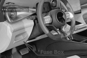
Access to fuse box:

  1. Open the glove compartment.
  2. Release the damper from the bottom holder by applying pressure toward the front, arrow 1.
  3. Unlock the glove compartment by pressing on both tabs, arrows 2, and fold down.
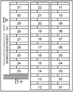
BMW X1 (E84) - fuse box diagram - passenger compartment fuse box
BMW X1 (E84) – fuse box diagram – passenger compartment fuse box
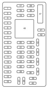
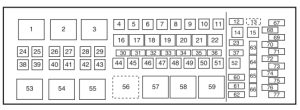
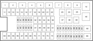
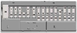
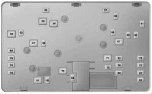
No.
A
Protected Component
1 20 Rear Intermittent Wipe/Wash Control Unit
2  –
3 20 Electrochromic Interior Rear View Mirror
4 10 N20, N46, N52, N55: DME Control Unit (16i, 18i, 20i, 28i, 35i)
5 10 Steering Column Switch Center
6 5 AUC Sensor, DC/DC Converter
7 5 Park Distance Control (PDC), Roof Function Control Centre
8 20 Front Cigar Lighter, Rear Centre Console Charging Socket 1 & 2, Luggage Compartment Socket Outlet
9 5 Driver’s Switch Cluster, Telephone Transceiver, Telephone Retrofit Packages Connector
10 5 Driver’s Seat Heating Module, Passenger’s Seat Heating Module
11 20 N20, N55: DME Control Unit
20 N46 TU 2: Fuel Injectors
20 N52: Oil Condition Sensor, DISA Actuator 1 & 2, Fuel Tank Vent Valve, Crankshaft Sensor, Air Mass Flow Sensor
12  –
13 10 TCU, ULF, ULF-SBX, ULF-SBX-H, Combox, Eject Box, USB Hub
14 15 Car Information Computer (CIC), Radio (without CIC)
15 20 Audio Amplifier
16 10 N20, N55: DME Control Unit
10 N52: Radiator Shutter Drive Unit, E-Box Fan
10 N46 TU 2: Crankshaft Sensor, Fuel Tank Vent Valve, Hot-Film Air Mass Meter, E-Box Fan
17 10 N20, N46, N52, N55:  Diagnostic Module for Fuel Tank Leakage, Exhaust Flap
18 10 Video Module, Digital Tuner
19 5 CD Changer
20 10 Driver’s/Passengers’s Lumbar Support Switch, Switch for Driver’s/Passenger’s Seat Backrest width Adjustment, Valve Block for Driver’s/Passenger’s Seat Backrest width Adjustment, Front Left/Right Lumbar Support Valve Block
21  –
22 15 Transmission Control, Transmission Control DKG
23  –
24  –
25 20 Panorama Glass Roof
26 5 Transfer Box Control Unit, Dynamic Stability Control (DSC)
27 5 Tyre Pressure Control (RDC)
28 5 Electric Fan Cut-Out Relay, DC/DC Converter
29 5 Korea: Tank Vent Shutoff Valve
30  –
31 30 Trailer Module
32 30 Trailer Module
33 40 except N20: Electric Coolant Pump
40 N47: Fuel Heater
34  –
35  –
36 40 Car Access System
37 10 N20: DME Control Unit
30 N46 TU 2: Oxygen Sensor before Catalytic Converter, Oxygen Sensor 2 before Catalytic Converter, Oxygen Sensor after Catalytic Converter, Oxygen Sensor 2 after Catalytic Converter
30 N52: Electric Coolant Pump, Characteristic Map Thermostat, Intake Camshaft Sensor, Exhaust Camshaft Sensor, Intake Vanos Solenoid Valve, Exhaust Vanos Solenoid Valve, Oil Pressure Control Valve
38 15 N20: DME Control Unit
30 N46 TU 2: Ignition Coils
30 N52: Oxygen Sensor before Catalytic Converter, Oxygen Sensor 2 before Catalytic Converter, Oxygen Sensor after Catalytic Converter, Oxygen Sensor 2 after Catalytic Converter, Crankshaft Breather Heating 1
39 30 N46 TU 2: DME Control Unit, Characteristic Map Thermostat, Intake Camshaft Sensor, Exhaust Camshaft Sensor, Intake Vanos Solenoid Valve, Exhaust Vanos Solenoid Valve, Oil Level Sensor, Crankcase Breather Heating
30 N52: Fuel Injectors, Ignition Coils, Interference Suppression Capacitor for Ignition Coils
40 30 Transfer Box Control Unit
41 30 Driver’s Window Motor, Footwell Module
42 40 Audio Amplifier (HiFi System Professional, BMW Individual High-End Audio System, Harman Kardon Surround Sound System)
43  –
44  –
45 30 Passenger’s Seat Adjustment Switch
46 30 Driver’s Seat Module
47 30 Right Lockout Circuit for Rear Window Defogger
48 30 Headlight Washer Pump
49 30 Passenger’s Seat Module
40 Active Steering
50 30 Wiper Motor
51  –
52  –
53  –
54 7.5 Siren and Tilt Alarm Sensor
55 5 Car Access System
56 20  –
57 15 Horn
58 5 All-Round Vision Camera
59 5 Combox, Telematics Control Unit (TCU) (USA), Eject Box (USA)
60  –
61 5 Comfort Access Control Unit, Driver’s Side Outer Door Handle Electronic Module, Passenger’s Side Outer Door Handle Electronic Module
62 7.5 Roof Function Control Centre
63 5 Gear Indicator Lighting, Aerial Diversity (Noise Suppressor Filter)
64  –
65 10 Longitudinal Dynamics Management, Gear Indicator Lighting (Automatic Transmission), Gear Selector Switch (Double Clutch Transmission)
66 7.5 Driver’s Switch Cluster, Passenger’s Side Outside Mirror
67 20 Electric Fuel Pump
68 20 Driver’s Seat Heating Module
69
70 20 Fuel Pump Control (EKPS)
71 20 Trailer Socket
72 15 Driver’s Door System Lock
73 15 Passenger’s Door System Lock
74 5 Instrument Cluster Control Unit
75 5 Steering Column Switch Cluster
76 10 Central Information Display
77 10 Luggage Compartment Light, Glove Compartment Light, Heating/Air Conditioning System
78 30 Rear Driver’s Side Power Window Motor
79 30  –
80 30 Rear Passenger’s Side Power Window Motor
81 30 Driver’s Window Motor
82 30 Dynamic Stability Control (DSC – without Automatic Engine Start-Stop), DC/DC Converter (with Automatic Engine Start-Stop)
83  –
84 40 Footwell Module
85 30 DC/DC Converter
86 40 Footwell Module
87  –
88 40 Blower Output Stage
89 40 Secondary Air Pump Relay
90 40 Dynamic Stability Control (DSC)
91 15 Passenger’s Door System Lock
92 50 Fan 400W: Electric Fan Cut-Out Relay
60 Fan 600W: Electric Fan Cut-Out Relay
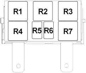
Relay
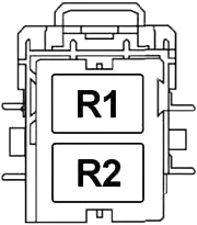
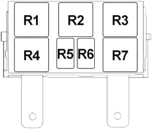
R1 Rear Window Wiper
R2 Wiper (Relay No.1)
R3 Terminal 30G
R4 Wiper (Relay No.2)
R5 Petrol: Digital Motor Electronics (DME) Main
R6 Headlight Cleaning System
R7 Fuel Pump

Secondary Air Pump Relay

BMW X1 (E84) - fuse box diagram - secondary air pump relay
BMW X1 (E84) – fuse box diagram – secondary air pump relay
  • Petrol Engines:
    sDrive16i – 1.6 Turbo (N20B16)
    sDrive18i – 2.0 L (N46B20)
    sDrive20i, sDrive28i & xDrive28i – 2.0 Turbo (N20B20)
    xDrive25i & xDrive28i (’11-’15) – 3.0 L (N52B30)
    xDrive35i – 3.0 Turbo (N55B30)
  • Diesel Engines:
    sDrive16d, sDrive18d, sDrive20d, sDrive20d EfficientDynamics – 2.0 Turbo (N47D20)
    xDrive18d, xDrive20d – 2.0 Turbo (N47D20)
    xDrive23d, xDrive25d – 2.0 Twin-Turbo (N47D20)

Engine Compartment Fuses (N20, N55)

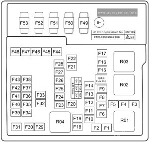
BMW X1 (E84) - fuse box diagram - engine compartment fuses (N20, N55)
BMW X1 (E84) – fuse box diagram – engine compartment fuses (N20, N55)
No.
A
Protected Component
8680  –
8681 15 N20: Digital Motor Electronics (DME) Control Unit
20 N55: Digital Motor Electronics (DME) Control Unit
8682 20 N20: Digital Motor Electronics (DME) Control Unit
15 N55: Digital Motor Electronics (DME) Control Unit
8683 40 N20: Digital Motor Electronics (DME) Control Unit
40 N55: Valvetronic Relay
8684  –   –
8685 30 Coolant Pump 200W (N20): Electric Coolant Pump
50 Coolant Pump 400W (N20): Electric Coolant Pump
Relay
R1 Variable Valve Gear
R2 Ignition and Fuel Injection


Variable Valve Gear/Ignition and Fuel Injection

BMW X1 (E84) - fuse box diagram - engine compartment - variable valve Gear
BMW X1 (E84) – fuse box diagram – engine compartment – variable valve Gear


Engine Compartment Fuses (N52)

BMW X1 (E84) - fuse box diagram - engine compartment fuse (N52)
BMW X1 (E84) – fuse box diagram – engine compartment fuse (N52)


No.
A
Protected Component
01 30 Ignition Coils, Interference Suppression Capacitor for Ignition Coils
02 30 Electric Coolant Pump, Characteristic Map Thermostat, Intake Camshaft Sensor, Exhaust Camshaft Sensor, Intake Vanos Solenoid Valve, Exhaust Vanos Solenoid Valve
03 20 Digital Motor Electronics (DME) Control Unit, Oil Condition Sensor, Disa Actuator No.1 & 2, Fuel Tank Vent Valve, Crankshaft Sensor, Air Mass Flow Sensor
04 10 Oxygen Sensor No.1 & 2 before Catalytic Converter, Oxygen Sensor No.1 & 2 after Catalytic Converter, Crankshaft Breather Heating
05 30 Fuel Injectors Relay
06 10 Secondary Air Pump Relay, Exxhaust Flap, E-Box Fan, Diagnostic Module for Fuel Tank Leakage (USA), Secondary Air – Hot-Film Air-Mass Meter
09 30 Electric Coolant Pump
Relay
R1 Digital Motor Electronics (DME)
R2 Fuel Injectors


Secondary Air Pump Relay

BMW X1 (E84) - fuse box diagram - engine compartment fuse secondary (air pump relay)
BMW X1 (E84) – fuse box diagram – engine compartment fuse secondary (air pump relay)


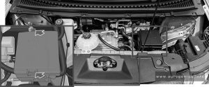
BMW X1 (E84) - fuse box diagram - engine compartment fuse box
BMW X1 (E84) – fuse box diagram – engine compartment fuse box
No.
A
Protected Component
07 40 VVT Relay
10 5 Engine Breather Heating
Relay
R3 Crankcase Ventilation Heater
R4 Electric Fan Cutoff
R5 VVT


Engine Compartment Fuses (Diesel N47)

BMW X1 (E84) - fuse box diagram - engine compartment fuse box (diesel N47)
BMW X1 (E84) – fuse box diagram – engine compartment fuse box (diesel N47)
No.
A
Protected Component
01 20 Boost Pressure Adjuster 1, Throttle Valve, Camshaft Sensor, Rail Pressure Control Valve, Volume Control Valve
20 25d: Rail Pressure Control Valve, Volume Control Valve, Camshaft Sensor, Turbine Control Valve, Changeover Valve Low Pressure Compressor Bypass Flap, Wastegate Valve
02 20 Exhaust Recirculation Actuator, Hot-Film Air Mass Meter, Exhaust Recirculation Cooler Bypass, Oxygen Sensor before Catalytic Converter, Preheating Control Unit, Oil Condition Sensor
20 25d: Oil Level Sensor, Exhaust Recirculation Cooler Bypass Solenoid Valve, Preheating Control Unit, Compressor Bypass Valve, Engine Mount Electrical Changeover Valve, Air Mass Flow Sensor, Oxygen Sensor before Catalytic Converter
03 30 Digital Diesel Electronics (DDE) Control Unit
04 10 E-Box Fan (except25d), Crankcase Breather Heating
05  –
Relay
R1 Electric Fan Cutoff
R2 Digital Diesel Electronics (DDE) Control Unit (Main Relay)


BMW X1 (E84) - fuse box diagram - engine compartment fuse box (diesel N47)
BMW X1 (E84) – fuse box diagram – engine compartment fuse box (diesel N47)
No.
A
Protected Component
26 5 with Start-Stop: Dynamic Stability Control (DSC)


Main Fuse Box (Battery)

No.
A
Protected Component
101 250 Passenger Compartment Fuse Box
102 100 Jump Start Terminal Point (DDE Main Relay)
103 100 Electromechanical Power Steering
104 100 Electric Auxiliary Heater (Diesel)
105 Battery Sensor


WARNING: Terminal and harness assignments for individual connectors will vary depending on vehicle equipment level, model, and market.

Volkswagen Baywindow Bus (1968 – 1969) – fuse box diagram

Volkswagen Baywindow Bus (1968 – 1969) – fuse box diagram

Year of production: 1968, 1969

Wiring diagrams (1968 and 1969 models)

Volkswagen Baywindow Bus - fuse box diagram -wiring diagram
Volkswagen Baywindow Bus – fuse box diagram -wiring diagram
No.
A
Protected Component
1 8 Emergency flasher, Brake warning light, Horn
2 8 Windshield wipers
3 8 Left high beam, High beam warning light
4 8 Right high beam
5 8 Left headlight
6 8 Right headlight
7 8 Parking lights front, Tail light right, License plate
8 8 Tail light left
9 8 Emergency flasher, Interior light front and rear
10 8 Accessory


The owner’s manuals aren’t clear which fuses are 8A and which are 16A and it varies from year to year. Bentley is even less clear and there is a mistake in the manual but the color wiring diagrams explain which fuses protection which circuits.


  • There are twelve fuses in fuseboxes of 70-79 models but only 10 in the 68-69 models.
  • 68-69 models only use 8A fuses.
  • Accessory means radio in most cases but can also mean gas heater in addition.
  • Fresh air fans were mainly available on non-US models for defogging the front windshield.

WARNING: Terminal and harness assignments for individual connectors will vary depending on vehicle equipment level, model, and market.
Volkswagen Baywindow Bus (1970) – fuse box diagram

Volkswagen Baywindow Bus (1970) – fuse box diagram

Year of production: 1970

Wiring diagrams (1970 models) (411 937 505A)

Volkswagen Baywindow Bus - fuse box diagram -wiring diagram
Volkswagen Baywindow Bus – fuse box diagram -wiring diagram


No.
A
Protected Component
1 8 Tail light right, Sidemarker rear right, License plate light, Parking lights front
2 8 Tail light left, Sidemarker rear left
3 8 Right headlight
4 8 Left headlight
5 8 Right high beam
6 8 Left high beam, High beam warning light
7 8 Accessory
8 16 Windshield wipers
9 8 Parking brake light, Alternator light, High beam warning light, Turn signal warning light, Fuel gauge
10 8 Horn, Brake warning light
11 8 Interior light front, Door buzzer, Emergency flasher, Turn signals
12 16 Interior light rear


The owner’s manuals aren’t clear which fuses are 8A and which are 16A and it varies from year to year. Bentley is even less clear and there is a mistake in the manual but the color wiring diagrams explain which fuses protection which circuits.


  • There are twelve fuses in fuseboxes of 70-79 models but only 10 in the 68-69 models.
  • 68-69 models only use 8A fuses.
  • Accessory means radio in most cases but can also mean gas heater in addition.
  • Fresh air fans were mainly available on non-US models for defogging the front windshield.

WARNING: Terminal and harness assignments for individual connectors will vary depending on vehicle equipment level, model, and market.
Volkswagen Baywindow Bus (1971) – fuse box diagram

Volkswagen Baywindow Bus (1971) – fuse box diagram


Year of production: 1971

Wiring diagrams (1971 models) (411 937 505B)

Volkswagen Baywindow Bus - fuse box diagram -wiring diagram
Volkswagen Baywindow Bus – fuse box diagram -wiring diagram
No.
A
Protected Component
1 8 Tail light right, Sidemarker rear right, License plate light
2 8 Tail light left, Sidemarker rear left
3 8 Right headlight
4 8 Left high beam
5 8 Right high beam
6 8 Left headlight, High beam warning light
7 8 Fresh air fans
8 8 Interior light front, Emergency flasher, Turn signals
9 16 Accessory, Door buzzer, Interior light rear
10 8 Brake lights, Horn
11 16 Rear defogger, Windshield wipers
12 8 Parking brake control light, Alternator light, Turn signal warning light, Fuel gauge

The owner’s manuals aren’t clear which fuses are 8A and which are 16A and it varies from year to year. Bentley is even less clear and there is a mistake in the manual but the color wiring diagrams explain which fuses protection which circuits.


  • There are twelve fuses in fuseboxes of 70-79 models but only 10 in the 68-69 models.
  • 68-69 models only use 8A fuses.
  • Accessory means radio in most cases but can also mean gas heater in addition.
  • Fresh air fans were mainly available on non-US models for defogging the front windshield.

WARNING: Terminal and harness assignments for individual connectors will vary depending on vehicle equipment level, model, and market.
Volkswagen Baywindow Bus (1972) – fuse box diagram

Volkswagen Baywindow Bus (1972) – fuse box diagram


Year of production: 1972

Wiring diagrams (1972 models) (411 937 505C)

Volkswagen Baywindow Bus - fuse box diagram -wiring diagram
Volkswagen Baywindow Bus – fuse box diagram -wiring diagram

Fuse box diagram

Volkswagen Baywindow Bus - fuse box diagram
Volkswagen Baywindow Bus – fuse box diagram
No.
A
Protected Component
1 8 Tail light left, Sidemarker rear left
2 8 Parking light front left and right, Tail light right, Sidemarker rear right, License plate light
3 8 Right headlight
4 8 Left headlight
5 8 Right high beam
6 8 Left high beam, High beam warning light
7 8 Fresh air fans
8 8 Interior light front, Emergency flasher, Turn signals
9 16 Accessory, Door buzzer, Interior light rear
10 16 Windshield wipers
11 8 Rear defogger, Oil warning light, Alternator light, Turn signal warning light, Gas gauge,
12 8 Horn, Brake lights, Brake warning light


The owner’s manuals aren’t clear which fuses are 8A and which are 16A and it varies from year to year. Bentley is even less clear and there is a mistake in the manual but the color wiring diagrams explain which fuses protection which circuits.


  • There are twelve fuses in fuseboxes of 70-79 models but only 10 in the 68-69 models.
  • 68-69 models only use 8A fuses.
  • Accessory means radio in most cases but can also mean gas heater in addition.
  • Fresh air fans were mainly available on non-US models for defogging the front windshield.

WARNING: Terminal and harness assignments for individual connectors will vary depending on vehicle equipment level, model, and market.
Volkswagen Baywindow Bus (1972 – 1975) – fuse box diagram

Volkswagen Baywindow Bus (1972 – 1975) – fuse box diagram


Year of production: 1972, 1973, 1974, 1975

Wiring diagrams (1973 through 1975 models)

Volkswagen Baywindow Bus - fuse box diagram -wiring diagram
Volkswagen Baywindow Bus – fuse box diagram -wiring diagram


Fuse box diagram

Volkswagen Baywindow Bus - fuse box diagram
Volkswagen Baywindow Bus – fuse box diagram
No.
A
Protected Component
1 8 Tail light left, Sidemarker rear left
2 8 Parking light left, Sidemarker front left and right, Parking light right, Sidemarker rear right, Tail light right, License plate light
3 8 Left headlight
4 8 Left high beam
5 8 Right headlight, High beam warning light
6 8 Right high beam
7 8 Fresh air fans
8 8 Interior light front, Emergency flasher and warning light, Turn signals
9 16 Accessory, Interior light rear, Door buzzer
10 16 Windshield wipers, Rear defogger and warning light
11 8 Oil warning light, Alternator light, Turn signal warning light, Gas gauge
12 8 Horn, Brake lights, Brake warning light, Parking brake control light


Note: 75 only differs by the wiring of the interior lights

No.
A
Protected Component
1 8 Tail light left, Sidemarker rear left
2 8 Parking light left, Sidemarker front left and right, Parking light right, Sidemarker rear right, Tail light right, License plate light
3 8 Left headlight
4 8 Left high beam
5 8 Right headlight, High beam warning light
6 8 Right high beam
7 8 Fresh air fans
8 8 Interior light front, Emergency flasher and warning light, Turn signals
9 16 Accessory, Door buzzer
10 16 Windshield wipers, Rear defogger and warning light
11 8 Oil warning light, Alternator light, Turn signal warning light, Gas gauge
12 8 Horn, Brake lights, Brake warning light, Parking brake control light

The owner’s manuals aren’t clear which fuses are 8A and which are 16A and it varies from year to year. Bentley is even less clear and there is a mistake in the manual but the color wiring diagrams explain which fuses protection which circuits.


  • There are twelve fuses in fuseboxes of 70-79 models but only 10 in the 68-69 models.
  • 68-69 models only use 8A fuses.
  • Accessory means radio in most cases but can also mean gas heater in addition.
  • Fresh air fans were mainly available on non-US models for defogging the front windshield.

WARNING: Terminal and harness assignments for individual connectors will vary depending on vehicle equipment level, model, and market.
Volkswagen Baywindow Bus (1976 – 1979) – fuse box diagram

Volkswagen Baywindow Bus (1976 – 1979) – fuse box diagram


Year of production: 1976, 1977, 1978, 1979

Wiring diagrams (1976 models)

Volkswagen Baywindow Bus - fuse box diagram -wiring diagram
Volkswagen Baywindow Bus – fuse box diagram -wiring diagram

Wiring diagrams (1977 – 1978 models)

Volkswagen Baywindow Bus - fuse box diagram -wiring diagram
Volkswagen Baywindow Bus – fuse box diagram -wiring diagram

Wiring diagrams (1979 models)

Volkswagen Baywindow Bus - fuse box diagram -wiring diagram (part 1)
Volkswagen Baywindow Bus – fuse box diagram -wiring diagram (part 1)
Volkswagen Baywindow Bus - fuse box diagram -wiring diagram (part 2)
Volkswagen Baywindow Bus – fuse box diagram -wiring diagram (part 2)
Volkswagen Baywindow Bus - fuse box diagram -wiring diagram (part 3)
Volkswagen Baywindow Bus – fuse box diagram -wiring diagram (part 3)


Fuse box diagram

Volkswagen Baywindow Bus - fuse box diagram
Volkswagen Baywindow Bus – fuse box diagram
No.
A
Protected Component
1 8 Tail light left, Sidemarker rear left
2 8 Parking light left, Sidemarker front left and right, Parking light right, Sidemarker rear right, Tail light right, License plate light
3 8 Left headlight
4 8 Left high beam
5 8 Right headlight, High beam warning light
6 8 Right high beam
7 8 Fresh air fans
8 8 Interior lights front and rear, Emergency flasher and warning light, Turn signals
9 16 Accessory
10 16 Windshield wipers, Rear defogger and warning light
11 8 Horn, Brake lights, Brake warning light, Parking brake control light
12 8 Oil warning light, Alternator light, Turn signal warning light, EGR warning light, Gas gauge


The owner’s manuals aren’t clear which fuses are 8A and which are 16A and it varies from year to year. Bentley is even less clear and there is a mistake in the manual but the color wiring diagrams explain which fuses protection which circuits.


  • There are twelve fuses in fuseboxes of 70-79 models but only 10 in the 68-69 models.
  • 68-69 models only use 8A fuses.
  • Accessory means radio in most cases but can also mean gas heater in addition.
  • Fresh air fans were mainly available on non-US models for defogging the front windshield.

WARNING: Terminal and harness assignments for individual connectors will vary depending on vehicle equipment level, model, and market.
BMW 2-Series Active Tourer and Gran Tourer (F45/F46) – (2014 – 2021) – fuse box diagram

BMW 2-Series Active Tourer and Gran Tourer (F45/F46) – (2014 – 2021) – fuse box diagram


Year of production: 2014, 2015, 2016, 2017, 2018, 2019, 2020, 2021

Passenger Compartment Fuse Box No.1

BMW 2-series - fuse box diagram - passenger compartment fuse box no. 1
BMW 2-series – fuse box diagram – passenger compartment fuse box no. 1
BMW 2-series - fuse box diagram - passenger compartment fuse box no. 1
BMW 2-series – fuse box diagram – passenger compartment fuse box no. 1
No.
A
Protected Component
30  –
31  –
32 40 Body Domain Controller
33  –
34 40 Blower Output Stage
35 50 Body Domain Controller
37 5 Parking Brake Button
38 5 Siren with Tilt Alarm Sensor
39 5 Roof Function Centre
40 5 Dynamic Stability Control (DSC)
41 5 Instrument Cluster Control Unit
42 5 Remote Control Receiver
43 30 Roof Function Centre
44 20 Right Headlight
45 30 without Electromechanical Parking Brake: Dynamic Stability Control (DSC)
40 with Electromechanical Parking Brake: Dynamic Stability Control (DSC)
46 5 Natural Vacuum Leak Detection
47 30 →02.16: Longitudinal Torque Distribution
20 03.16→: Left Headlight
48 30 Selective Catalytic Reduction (SCR) Control Unit
49 5 Electrical Exhaust Flap, Control Electronics for Electric Auxiliary Heater No.2
50 5 Radiator Shutter Drive Unit, Environmental Air Catalyst Sensor (except PHEV)
51 5 Base Plate Fan
52 5 Electrochromic Interior Rear View Mirror
53 5 Automatic Recirculated Air Control (AUC) Sensor
54 5 Electromechanical Power Steering
55 4 Reversing Camera, Camera-Based Driver Assistance System (→06.15), Parking Assistant
56 5 Longitudinal Torque Distribution, Vehicle Sound Generator (PHEV), Vehicle Sound Generator No.2 (PHEV)
57  –
58 10 Steering Column Switch Cluster
59 5 Camera-Based Driver Assistance System
60 5 Optional Extra System
61 20 Headunit (Radio or Navigation System)
62 5 Front Interior Light, Rain Light Solar Condensation Sensor, Vanity Mirror Light, Third Row of Seats Interior Light
63 20 Trailer Socket
64  –
65 20 Front Cigarette Lighter (12 V Power Socket), Power Socket (under Glove Box)
66 20 Electric Fuel Pump Control Electronics
67 7.5 →06.17: Exterior Mirror (Front Passenger)
5 07.17→: Exterior Mirror (Front Passenger)
68 5 Touchbox, Controller (CON), USB Hub, USB Charging Socket No.3
69 7.5 →06.17: Exterior Mirror (Switch Block – Driver’s Door)
5 07.17→: Exterior Mirror (Switch Block – Driver’s Door)
70 5 Luggage Compartment Light, Glove Compartment Light, Rear Lid Button on Inside of Rear Lid
71 7.5 Instrument Cluster Control Unit
72 5 Electric Fan Cut-Out Relay
73 10 Driver’s Seat Backrest with Adjustment (Valve Block), Driver Lumbar Support Valve Block, Switch for Backrest Width Adjustment Driver’s Seat
74 7.5 Petrol (TU): Turbocharger Coolant Pump
75 10 Front Passenger Seat Backrest with Adjustment (Valve Block), Passenger Lumbar Support Valve Block, Switch for Backrest Width Adjustment Passenger Seat
76 5 →06.17: Front Interior Light
77 10 Nitrogen Oxide Sensor after Selective Catalytic Reduction (SCR) Catalytic Converter, Diesel Particulate Sensor
78 15 Selective Catalytic Reduction (SCR) Control Unit
79 5 Base Plate, Wireless Charging Oddments Tray, Wireless Charging Oddments Tray Aerial Amplifier
80 5 Front Interior Light
81 15 Electronic Transmission Control
82 5 Selector Level
83 5 →06.16: Digital Motor Electronics
7.5 07.16→: Digital Motor Electronics
84 5 with Manual Transmission: Clutch Module
5 with Twin-Clutch Gearbox: Twin-Clutch Gearbox Control Unit, Twin-Clutch Gearbox Relay
85 5 Electrochromic Interior Rear View Mirror
86  –
87  –
88  –
89  –
90 5 Automatic Luggage Compartment Lid Actuation
91  –
92 10 Optional Extra System
93 15 Boot Lid/Tailgate Lock
94 20 Backrest Remote Unlocking Control Electronics
95 30 Front Passenger Side Seat Adjustment Switch Block
96 10 Boot Lid/Tailgate Lock
97 5 Auxiliary Control Unit
98  –
99  –
100 5 PHEV: High-Voltage Battery Unit
101 5 ID Reader, Car Sharing Module (CSM)
102  –
103 20 Right Headlight
104 20 Left Headlight
105  –
106  –
107 40 →06.17: Automatic Luggage Compartment Lid Actuation
40 07.17→: Tailgate Function Module
108  –
109 5 Bi-Stable Relay
110 5 Bi-Stable Relay
111 5 Bi-Stable Relay
112  –
113 10 PHEV (06.16): Pressurised Fuel Tank Control Module
114  –
115 5 PHEV: Convenience Charging Electronics
116  –
117  –
118  –
119 20 Trailer Module
120 20 Trailer Module
121 7.5 USB Charging Socket No.4
122 5 PHEV: Safety Battery Terminal Gas Generator
123 5 PHEV: Electrical A/C Compressor, Electric Auxiliary Heater
124 10 PHEV: Electric-Machine Electronics
125  –
126  –
127 30 Driver’s Seat Heating Electronics (Basic Version), Driver’s Seat Module (High Version)
128 30 Front Passenger Seat Heating Electronics
129 30 HiFi Amplifier
130 10 PHEV: Coolant Pump 2 in Low-Temperature Coolant Circuit
131 30 Longitudinal Torque Distribution (07.15→), Transmission Oil Pump (PHEV)
132 20 Under Armrest Power Socket, Rear Power Socket (→06.18), Luggage Compartment Power Socket

Passenger Compartment Fuse Box No.2

BMW 2-series - fuse box diagram - passenger compartment fuse box no. 2
BMW 2-series – fuse box diagram – passenger compartment fuse box no. 2
No.
A
Protected Component
1 30 Power Window (Passenger)
2 30 Power Window (Driver’s Side – Rear)
3 20 Door Lock (Front Passenger)
4 30 Power Window (Driver)
5 30 Rear Window Defogger
6 30 Power Window (Passenger Side – Rear)
7 30 Door Lock (Driver)
8  –
9 5 Light Operating Unit, Steering Column Switch Cluster, Driver Assistance System Operating Facility with Hazard Warning Switch
10 7.5 Diagnosis Socket
11 7.5 Diagnosis Socket (→06.14), Heating/Air Conditioning System, Tailgate Function Module (07.17→)
12 5 Evaluation Electronics for Contact-Free Tailgate Opening, Telematic Communication Box, Electronic Outer Door Handle Module (Driver/Passenger)
13 15 Horn
14  –


Integrated Supply Module

Petrol engines:

B38 – 1.5L (216i, 218i, 225xe)

BMW 2-series - fuse box diagram - integrated supply module (petrol - B38)
BMW 2-series – fuse box diagram – integrated supply module (petrol – B38)


B48 – 2.0L (220i, 225i, 225i xDrive & 225xe PHEV)

BMW 2-series - fuse box diagram - integrated supply module (petrol - B48)
BMW 2-series – fuse box diagram – integrated supply module (petrol – B48)


Diesel engines:

B37 – 1.5L (214d, 216d)

BMW 2-series - fuse box diagram - integrated supply module (diesel - B37)
BMW 2-series – fuse box diagram – integrated supply module (diesel – B37)


B47 – 2.0L (218d, 218d xDrive, 220d, 220d xDrive)

BMW 2-series - fuse box diagram - integrated supply module (diesel - B47)
BMW 2-series – fuse box diagram – integrated supply module (diesel – B47)


!!! The integrated supply module contains fuses and relays. If one of the fuses or one of the relays is faulty, the complete integrated supply module must be renewed !!!

No.
A
Protected Component
01 7.5 Diesel: Oil Pressure Control Valve, Oil-Level Sensor, Compressor Bypass Plate Changeover Valve (except 2.0L B47)
20 Petrol, PHEV: Digital Motor Electronics (DME)   PHEV
7.5 Petrol (TU): Heat Management Module, Oil Pressure Control Valve, Oil-Level Sensor
02 7.5 Diesel: Coolant Pump Changeover Valve, Piston Cooling Solenoid Valve
15 Petrol, PHEV: Digital Motor Electronics (DME)    PHEV
03 7.5 Diesel: Fuel Quantity Control Valve
10 Petrol, PHEV: Digital Motor Electronics (DME)
04 7.5 except B47 TOP: Turbine Control Flap Pressure Converter
7.5 B47 TOP: Coolant Shutoff Valve for Low-Pressure Stage Turbocharger
15 Petrol, PHEV: Digital Motor Electronics (DME)
15 Petrol (TU): Engine Ventilation Heating, Blow-Off Valve (B48)
05 15 Diesel: Digital Diesel Electronics (DDE)
20 Petrol, PHEV: Digital Motor Electronics (DME)
20 Petrol (TU): Oxygen Sensor after Catalytic Converter, Oxygen Sensor before Catalytic Converter
06
20 Diesel: EGR Cooler Bypass Flap Changeover Valve, Nitrogen Oxide Sensor before SCR Catalytic Converter
40 Petrol: Digital Motor Electronics (DME)
07 15 Diesel: Oxygen Sensor before Catalytic Converter, Oxygen Sensor after Catalytic Converter
50 Petrol, PHEV: Electric Fan
08
5 Diesel: Digital Diesel Electronics (DDE), Rail Pressure Regulating Valve
  15 Petrol (TU): Digital Motor Electronics (DME)
09
40 B37 with Twin-Clutch Gearbox: Starter
010
30 Diesel: Digital Diesel Electronics (DDE)
011
40 Diesel: Fuel Filter Heating
014
40 Diesel: Digital Diesel Electronics (DDE)
015
40 Diesel: Digital Diesel Electronics (DDE)
018
10 Petrol (TU): Digital Motor Electronics (DME), Intake VANOS Solenoid Actuator, Exhaust VANOS Solenoid Actuator, Tank Vent Valve

Power Distribution Box (Diesel 1.5 & 2.0L)

Diesel engines:

B37, B47 – 1.5L (214d, 216d), 2.0L (218d, 218d xDrive, 220d, 220d xDrive)

BMW 2-series - fuse- box diagram - power distribution box (diesel - B37, B47)
BMW 2-series – fuse-
box diagram – power distribution box (diesel – B37, B47)

!!! The integrated supply module contains fuses and relays. If one of the fuses or one of the relays is faulty, the complete integrated supply module must be renewed !!!

No. A Protected Component
01 20 Preheating Control Unit, Rail Pressure Regulating Valve, Fuel Quantity Control Valve, Oil Pressure Control Valve, Coolant Pump Changeover Valve, Pressure Converter – Turbine Control Flap (2.0L B47), Charging Pressure Controller – Low Pressure Stage (2.0L B47)
02 20 Oil Level Sensor, Oxygen Sensor after Catalytic Converter, EGR Cooler Bypass Flap Changeover Valve, Oxygen Sensor before Catalytic Converter, Changeover Valve – Compressor Bypass Plate (2.0L B47)
03 20 Digital Diesel Electronics (DDE)
04 20 Digital Diesel Electronics (DDE)
05 20 Digital Diesel Electronics (DDE)

Fusible Link Block

BMW 2-series - fuse box diagram - fusible link block
BMW 2-series – fuse box diagram – fusible link block
No. A Protected Component
400 250 Front Power Distribution Box
401 60 Fan →400W: Electric Fan Cut-Out Relay
80 Fan 600W: Electric Fan Cut-Out Relay
125 Fan 800W: Electric Fan Cut-Out Relay
402 125 Electromechanical Power Steering
403 50 →06.18: Dynamic Stability Control (DSC)
60 07.18→: Dynamic Stability Control (DSC)
404 125 Body Domain Controller
405 100 Front Electric Auxiliary Heater
406 40 Diesel: Fuel Filter Heating
40 Steptronic with Double Clutch: Twin-Clutch Gearbox Relay
60 Control Electronics for Electric Auxiliary Heater in Engine Compartment


WARNING: Terminal and harness assignments for individual connectors will vary depending on vehicle equipment level, model, and market.
BMW X1 (F48 & F49) – (2015 – 2022) – fuse box diagram

BMW X1 (F48 & F49) – (2015 – 2022) – fuse box diagram


Year of production: 2015, 2016, 2017, 2018, 2019, 2020, 2021, 2022

Passenger Compartment Fuse Box No.1

BMW X1 - fuse box diagram - passenger compartment fuse box no. 1
BMW X1 – fuse box diagram – passenger compartment fuse box no. 1


BMW X1 - fuse box diagram - passenger compartment fuse box no. 1
BMW X1 – fuse box diagram – passenger compartment fuse box no. 1
No.
A
Protected Component
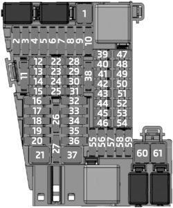
1 30 Power Window (Passenger)
2 30 Power Window (Driver’s Side – Rear)
3 20 Door Lock (Front Passenger)
4 30 Power Window (Driver)
5 30 Rear Window Defogger
6 30 Power Window (Passenger Side – Rear)
7 20 Door Lock (Driver)
8  –
9 5 Light Operating Unit, Steering Column Switch Cluster, Driver Assistance System Operating Facility with Hazard Warning Switch
10 7.5 Diagnosis Socket
11 7.5 Heating/Air Conditioning System, Tailgate Function Module (07.17→)
12 5 Evaluation Electronics for Contact-Free Tailgate Opening, Telematic Communication Box, Electronic Outer Door Handle Module (Driver/Passenger)
13 15 Horn
14  –

Passenger Compartment Fuse Box No.2

BMW X1 - fuse box diagram - passenger compartment fuse box no. 2
BMW X1 – fuse box diagram – passenger compartment fuse box no. 2


BMW X1 - fuse box diagram - passenger compartment fuse box no. 2
BMW X1 – fuse box diagram – passenger compartment fuse box no. 2
No.
A
Protected Component
30  –
31  –
32 40 Body Domain Controller
33  –
34 40 Blower Output Stage
35 50 Body Domain Controller
37 5 Parking Brake Button
38 5 Siren with Tilt Alarm Sensor
39 5 Roof Function Centre
40 5 Dynamic Stability Control (DSC)
41 5 Instrument Cluster Control Unit
42 5 Remote Control Receiver
43 30 Roof Function Centre
44 20 Right Headlight
45 30 without Electromechanical Parking Brake: Dynamic Stability Control (DSC)
40 with Electromechanical Parking Brake: Dynamic Stability Control (DSC)
46 5 Natural Vacuum Leak Detection
47 30 →02.16: Longitudinal Torque Distribution
20 03.16→: Left Headlight
48 30 Selective Catalytic Reduction (SCR) Control Unit
49 5 Electrical Exhaust Flap, Control Electronics for Electric Auxiliary Heater No.2
50 5 Radiator Shutter Drive Unit, Environmental Air Catalyst Sensor (except PHEV)
51 5 Base Plate Fan
52 5 Electrochromic Interior Rear View Mirror
53 5 Automatic Recirculated Air Control (AUC) Sensor
54 5 Electromechanical Power Steering
55 4 Reversing Camera, Parking Assistant
56 5 Longitudinal Torque Distribution, Vehicle Sound Generator (PHEV), Vehicle Sound Generator No.2 (PHEV)
57  –
58 10 Steering Column Switch Cluster
59 5 Camera-Based Driver Assistance System
60 5 Optional Extra System
61 20 Headunit (Radio or Navigation System)
62 5 Front Interior Light, Rain Light Solar Condensation Sensor, Vanity Mirror Lights, Third Row of Seats Interior Light, Decor Strip Lighting, Interior Trim Finisher Lighting, Door Trim Panel Lighting
63 20 Trailer Socket
64  –
65 20 Front Cigarette Lighter (12 V Power Socket), Power Socket (under Glove Box)
66 20 Electric Fuel Pump Control Electronics
67 7.5 →06.17: Exterior Mirror (Front Passenger)
5 07.17→: Exterior Mirror (Front Passenger)
68 5 Touchbox, Controller (CON), USB Hub, USB Charging Socket No.3
69 7.5 →06.17: Exterior Mirror (Switch Block – Driver’s Door)
5 07.17→: Exterior Mirror (Switch Block – Driver’s Door)
70 5 Luggage Compartment Light, Glove Compartment Light, Rear Lid Button on Inside of Rear Lid
71 7.5 Instrument Cluster Control Unit
72 5 Electric Fan Cut-Out Relay
5 Fan → 400W: Integrated Supply Module
73 10 Driver’s Seat Backrest with Adjustment (Valve Block), Driver Lumbar Support Valve Block, Switch for Backrest Width Adjustment Driver’s Seat
74 7.5 Petrol (TU): Turbocharger Coolant Pump
75 10 Front Passenger Seat Backrest with Adjustment (Valve Block), Passenger Lumbar Support Valve Block, Switch for Backrest Width Adjustment Passenger Seat
76 5 →06.17: Front Interior Light
77 10 Nitrogen Oxide Sensor after Selective Catalytic Reduction (SCR) Catalytic Converter
78 15 Selective Catalytic Reduction (SCR) Control Unit
79 5 Base Plate, Wireless Charging Oddments Tray, Wireless Charging Oddments Tray Aerial Amplifier
80 5 Front Interior Light
81 15 Electronic Transmission Control
82 5 Selector Level (Gear Selector Switch)
83 5 →06.16: Digital Motor Electronics
7.5 07.16→: Digital Motor Electronics
84 5 with Manual Transmission: Clutch Module
5 with Twin-Clutch Gearbox: Twin-Clutch Gearbox Control Unit, Twin-Clutch Gearbox Relay
85 5 Electrochromic Interior Rear View Mirror
86  –
87  –
88  –
89  –
90 5 Automatic Luggage Compartment Lid Actuation
91  –
92 10 Optional Extra System
93  –
94 20 Backrest Remote Unlocking Control Electronics
95 30 Front Passenger Side Seat Adjustment Switch Block
96 10 Boot Lid/Tailgate Lock
97 5 Auxiliary Control Unit
98  –
99  –
100 5 PHEV: High-Voltage Battery Unit
101 5 ID Reader, Car Sharing Module (CSM)
102  –
103 20 Right Headlight
104 20 Left Headlight
105  –
106  –
107 40 →06.17: Automatic Luggage Compartment Lid Actuation
40 07.17→: Tailgate Function Module
108 30 03.20→: Tailgate Function Module
109 5 Bi-Stable Relay
110 5 Bi-Stable Relay
111 5 Bi-Stable Relay
112  –
113 10 PHEV (06.16): Pressurised Fuel Tank Control Module
114  –
115 5 PHEV: Convenience Charging Electronics
116  –
117  –
118  –
119 20 Trailer Module
120 20 Trailer Module
121 7.5 USB Charging Socket No.4
122 5 PHEV: Safety Battery Terminal Gas Generator
123 5 PHEV: Electrical A/C Compressor, Electric Auxiliary Heater
124 10 PHEV: Electric-Machine Electronics
125  –
126  –
127 30 Driver’s Seat Heating Electronics (Basic Version), Driver’s Seat Module (High Version)
128 30 Front Passenger Seat Heating Electronics
129 30 HiFi Amplifier
130 10 Petrol: Coolant Pump 2 in Low-Temperature Coolant Circuit
131 30 Longitudinal Torque Distribution, Transmission Oil Pump (PHEV)
132 20 Under Armrest Power Socket, Rear Power Socket (→06.18), Luggage Compartment Power Socket

Fusible Link Block

BMW X1 - fuse box diagram - fusible link block
BMW X1 – fuse box diagram – fusible link block
No.
A
Protected Component
400 250 Front Power Distribution Box
401 60 Fan →400W: Electric Fan Cut-Out Relay
80 Fan 600W: Electric Fan Cut-Out Relay
125 Fan 800W: Electric Fan Cut-Out Relay
402 125 Electromechanical Power Steering
403 50 →06.18: Dynamic Stability Control (DSC)
60 07.18→: Dynamic Stability Control (DSC)
404 125 Body Domain Controller
405 100 Front Electric Auxiliary Heater
406 40 Diesel: Fuel Filter Heating
40 Steptronic with Double Clutch: Twin-Clutch Gearbox Relay
60 Control Electronics for Electric Auxiliary Heater in Engine Compartment


Integrated Supply Module (Petrol)

Except TU
BMW X1 - fuse box diagram - integrated supply module - petrol (except TU)
BMW X1 – fuse box diagram – integrated supply module – petrol (except TU)


TU
BMW X1 - fuse box diagram - integrated supply module - petrol (TU)
BMW X1 – fuse box diagram – integrated supply module – petrol (TU)
  • B38, B48 (sDrive18i, sDrive20i, xDrive20i, xDrive25i, xDrive28i and xDrive25e Hybrid) – except TU / TU

!!! The integrated supply module contains fuses and relays. If one of the fuses or one of the relays is faulty, the complete integrated supply module must be renewed !!!

No.
A
Protected Component
01 20 except TU, PHEV: Digital Motor Electronics (DME)
7.5 TU: Heat Management Module, Oil Pressure Control Valve, Oil-Level Sensor
02 15 except TU, PHEV: Digital Motor Electronics (DME)
03 10 except TU, PHEV: Digital Motor Electronics (DME)
04 15 except TU, PHEV: Digital Motor Electronics (DME)
15 TU: Engine Ventilation Heating, Blow-Off Valve (B48)
05 20 except TU, PHEV: Digital Motor Electronics (DME)
20 TU: Oxygen Sensor after Catalytic Converter, Oxygen Sensor before Catalytic Converter
06
40 except TU: Digital Motor Electronics (DME)
07 50 except TU, PHEV: Electric Fan
08 15 TU: Digital Motor Electronics (DME)
09
 –
010
30 TU: Digital Motor Electronics (DME)
011 20 TU: Digital Motor Electronics (DME)
014
40 TU: Digital Motor Electronics (DME)
018
10 TU: Digital Motor Electronics (DME), Intake VANOS Solenoid Actuator, Exhaust VANOS Solenoid Actuator, Tank Vent Valve

Power Distribution Box (Diesel)

BMW X1 - fuse box diagram - power distribution box (diesel)
BMW X1 – fuse box diagram – power distribution box (diesel)
  • B37 (sDrive16d), B47 (sDrive18d, sDrive20d and xDrive25d)

!!! The integrated supply module contains fuses and relays. If one of the fuses or one of the relays is faulty, the complete integrated supply module must be renewed !!!

No. A Protected Component
01 20 Preheating Control Unit, Rail Pressure Regulating Valve, Fuel Quantity Control Valve, Oil Pressure Control Valve, Coolant Pump Changeover Valve, Pressure Converter – Turbine Control Flap (2.0L B47 TOP), Charging Pressure Controller – Low Pressure Stage (2.0L B47 TOP)
02 20 Oil Level Sensor, Oxygen Sensor after Catalytic Converter, EGR Cooler Bypass Flap Changeover Valve, Oxygen Sensor before Catalytic Converter, Changeover Valve – Compressor Bypass Plate (2.0L B47 TOP)
03 20 Digital Diesel Electronics (DDE)
04 20 Digital Diesel Electronics (DDE)
05 20 Digital Diesel Electronics (DDE)

Integrated Supply Module (Diesel)

BMW X1 - fuse box diagram - integrated supply module (diesel)
BMW X1 – fuse box diagram – integrated supply module (diesel)
  • B37 (sDrive16d), B47 (sDrive18d, sDrive20d and xDrive25d)

!!! The integrated supply module contains fuses and relays. If one of the fuses or one of the relays is faulty, the complete integrated supply module must be renewed !!!

No. A Protected Component
01 7.5 Oil Pressure Control Valve, Oil-Level Sensor, Compressor Bypass Plate Changeover Valve (except 2.0L B47)
02 7.5 Coolant Pump Changeover Valve, Piston Cooling Solenoid Valve
03 7.5 Fuel Quantity Control Valve
04 7.5 except B47 TOP: Turbine Control Flap Pressure Converter
7.5 B47 TOP: Coolant Shutoff Valve for Low-Pressure Stage Turbocharger
05 15 Digital Diesel Electronics (DDE)
06
20 EGR Cooler Bypass Flap Changeover Valve, Nitrogen Oxide Sensor before SCR Catalytic Converter
07 15 Oxygen Sensor before Catalytic Converter, Oxygen Sensor after Catalytic Converter
08
5 Digital Diesel Electronics (DDE), Rail Pressure Regulating Valve
09
40 B37 with Twin-Clutch Gearbox: Starter
010
30 Digital Diesel Electronics (DDE)
011
40 Fuel Filter Heating
014
40 Digital Diesel Electronics (DDE)
015
40 Digital Diesel Electronics (DDE)


WARNING: Terminal and harness assignments for individual connectors will vary depending on vehicle equipment level, model, and market.
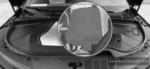
BMW X5 (G05/G18/F95) – (2018 – 2022) – fuse box diagram

BMW X5 (G05/G18/F95) – (2018 – 2022) – fuse box diagram

Year of production: 2018, 2019, 2020, 2021, 2022

Passenger Compartment Fuse Box No.1 (Passenger’s Side)

BMW X5 - fuse box diagram - passenger compartment box no. 1 (passenger's side)
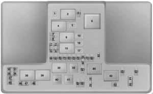
BMW X5 – fuse box diagram – passenger compartment box no. 1 (passenger’s side)
No.
A
Protected Component
20 30 Driver’s Door Power Window Drive with Control Electronics
21 30 Front Passenger Door Power Window Drive with Control Electronics
22 30 Driver’s Side Rear Power Window Drive with Control Electronics
23 30 Passenger’s Side Rear Power Window Drive with Control Electronics
24 30 Left Reversible Electromotive Automatic Reel (Seat Belt)
25 20 Roof Function Centre
26 20 Body Domain Controller
27  –
28 40 Dynamic Stability Control (DSC)
29 15 Body Domain Controller
30  –
31  –
32 5 Centre Console Control Panel
33 5 Driver Electronic Outer Door Handle Module
34 5 Instrument Cluster Control Unit
35 5 Auxiliary Control Unit
36 5 Roof Function Centre (Map Reading Light, Interior Light, Ambient Light)
37 10 Output Stage for Rear Compartment Fan Motor (4-zone Air Conditioning)
38  –
39 60 Body Domain Controller
40 40 Blower Motor with Output Stage
41  –
46 20 Rear Cigarette Lighter, Front Cigarette Lighter (without Thermoelectric Cup Holder), Thermoelectric Cup Holder
47 30 Wiper Module
48  –
49 20 Electric Steering Column Adjustment
50 15 Thermoelectric Cup Holder
51 30 B46, B48, B58, N63: Electronic Transmission Control, Transfer Box
52 20 Front Passenger Seat Heating Electronics
53 30 Driver’s Seat Module (with Seat Module), Driver’s Side Seat Adjustment Switch Block (without Seat Module)
54 20 Independent Auxiliary Heater (SHZH)
55 30 Front Passenger Seat Module (with Seat Module), Front Passenger Side Seat Adjustment Switch Block (without Seat Module)
56 10 Front Passenger’s Side Control Electronics for Armrest Heating
57 10 Driver’s Side Control Electronics for Armrest Heating
59 5 USB Connection No.2, Electrochromic Interior Rear View Mirror
60 5 Centre Rear Door Trim Panel Lighting (Driver’s Side), Rear Door Pocket Lighting (Driver’s Side), Rear Inner Door Handle Lighting (Driver’s Side), Rear Driver’s Side Door Trim Panel Lighting (Top), Rear Left Speaker Lighting, Auxiliary Water Pump (Diesel)
61 5 Glove Compartment Light Switch, Driver Camera System, 48 Volt Power Control Unit (PCU48), 48 Volt Battery
62  –
63 5 Auxiliary Battery, Instrument Panel Speaker Lighting, Air Freshener, CD Drive, Ioniser, Starter Motor Generator 48 Volt (B57, B58)
64 10 Driver’s Seat Backrest width Adjustment Valve Block, Driver Lumbar Support Valve Block, Seat Adjustment Switch Block (Driver’s Side), Rear Footwell Light (Driver’s Side), Driver’s Seat Backrest Rear Panel Lighting, USB Charging Socket, Front Left Seat Inflator Module
65 10 Front Passenger Backrest width Adjustment Valve Block, Front Passenger Lumbar Support Valve Block, Seat Adjustment Switch Block (Front Passenger Side), Rear Footwell Light (Front Passenger Side), Front Passenger Seat Backrest Rear Panel Lighting, USB Charging Socket No.2, Front Right Seat Inflator Module
66 5 Top Centre Dashboard Lighting, Top Front Passenger’s Side Instrument Panel Lighting, Bottom Centre Instrument Panel Lighting, Bottom Driver’s/Passenger’s Side Instrument Panel Lighting, Front Left/Right Footwell Light
67 5 Driver’s Door Switch Block, Seat Switch Cluster on Driver’s Door, Driver’s Door Inner Door Handle Lighting, Driver’s Door Trim Panel Lighting (Centre), Driver’s Door Pocket Lighting, Driver’s Door Trim Panel Lighting (Top), Front Left Mid-Range Speaker Lighting, Front Left Tweeter Lighting
68 5 Front Passenger Exterior Mirror, Passenger’s Door Switch Block, Passenger’s Door Inner Door Handle Lighting, Front Passenger Door Trim Panel Lighting (Centre), Passenger’s Door Pocket Lighting, Front Passenger Door Trim Panel Lighting (Top), Front Right Mid-Range Speaker Lighting, Front Right Tweeter Lighting
69 5 Radiator Blind Drive (Top, Bottom)
70 5 Rear Power Distribution Box, Electric Fan Cut-Out Relay, Electric Fan
71 5 All-Round Vision Camera (with Omnidirectional Camera), Reversing Camera
72  –
73 5 Instrument Cluster Control Unit
74 10 Steering Column Switch Cluster
75 10 Crash Safety Module
76  –
Relay
R1 Terminal 30B

Passenger Compartment Fuse Box No.2 (Passenger’s Side (Body Domain Controller))

BMW X5 - fuse box diagram - passenger compartment box no. 2 (passenger's side - body domain controller)
BMW X5 – fuse box diagram – passenger compartment box no. 2 (passenger’s side – body domain controller)
No.
A
Protected Component
1 5 Steering Column Switch Cluster, Front Centre Ventilation Grille, Audio Control Panel, Light Operating Unit, Headunit
2 7.5 Diagnosis Socket, Electronic Ride-Height Control, Vertical Dynamics Platform
3 7.5 Heating/Air Conditioning System, Tailgate Function Module, Rain/Light/Solar/Condensation Sensor
4 5 Passenger Electronic Outer Door Handle Module, Rear Driver’s Side Outer Door Handle Electronic Module, Rear Passenger’s Side Outer Door Handle Electronic Module, Power Control Unit, Telematic Communication Box
5 20 Locking Relay, Unlocking Relay (Doors, Fuel Filler Flap)
6 20 Driver’s Door Locking Relay, Deadlocking Relay (Driver’s Door Lock, Front Passenger Door Lock, Rear Driver’s Side Doorl Lock, Rear Passenger’s Side Door Lock, Fuel Filler Flap Central Locking Locking Drive)

Passenger Compartment Fuse Box No.3 (Driver’s Side)

BMW X5 - fuse box diagram - passenger compartment box no. 2 (driver's side)
BMW X5 – fuse box diagram – passenger compartment box no. 2 (driver’s side)
No.
A
Protected Component
101  –
102  –
103  –
104  –
105 7.5 Electric Machine Electronics
106  –
107 10 Hybrid: Pressurised Fuel Tank Control Module
108  –
109  –
110 5 Electric Auxiliary Heater, Lighting of Front Mid-Range Speaker
111 5 Rear Power Distribution Box
112  –
113  –
114  –
115  –
116  –
117 30 Hybrid:  Automatic Transmission, Transfer Box
118  –
119  –
120  –
121  –
122  –
123  –
124  –
125  –
126  –
127  –
128  –
129  –
130  –
131  –
Relay
R1
R2 Terminal 30B


Luggage Compartment Fuse Box

BMW X5 - fuse box diagram - luggage compartment fuse box
BMW X5 – fuse box diagram – luggage compartment fuse box
No.
A
Protected Component
200  –
201  –
202  –
203 7.5 Electrical Exhaust Flap (B46, B46, B58, N63, S63), Electrical Exhaust Flap No.2 (N63, S63)
204 5 Rear Axle King Pin Inclination Control, AUC Sensor, Regulated Rear Axle Differential Lock
205  –
206  –
207 5 Front Left/Right Side Radar Sensor Near Range, Rear Left/Right Radar Sensor Near, Optional Extra System
208 5 Electromechanical Power Steering
209 5 Long-Distance Range Front Radar Sensor (Active Cruise Control (High Version)), Front Radar Sensor (Basic Cruise Control (High Version)), Front Electric Active Roll Stabilisation, Rear Electric Active Roll Stabilisation
210 5 Electric Fuel Pump Control Electronics
211 5 Electronic Night Vision Module (BMW Night Vision)
212 15 Headunit
213 15 Trailer Socket
214 5 Booster
215 10 Rear Seat Entertainment
216 5 Wireless Charging Oddments Tray Aerial Amplifier
217 40 Booster
218 20 12V Connection No.2 (Luggage Compartment)
219  –
220 30 Receiver Audio Module
221  –
222  –
223  –
224 20 Vertical Dynamics Platform (Executive Drive Pro)
225  –
226 40 Tailgate Function Module
227 30 Selective Catalytic Reduction (SCR) Control Unit
228  –
229  –
230 30 Right Reversible Electromotive Automatic Reel (Seat Belt)
231 30 Rear Window Defogger
232  –
233  –
234  –
235  –
236  –
237  –
238  –
239  –
240 20 Trailer Module
242  –
243  –
244 5 Remote Control Receiver, Natural Vacuum Leak Detection, Siren with Tilt Alarm Sensor, High-Voltage Battery Unit (Hybrid), Safety Battery Terminal Gas Generator (with Dual Storage System, with 48V System)
245  –
246  –
247 15 Anti-Slip Rails Control Electronics
248 15 Retractable Roller Cover for Luggage Compartment Control Electronics
249 10 Passenger’s Door Automatic Soft-Close Drive
250 5 Interior Lights, Vanity Mirror Lights, Glass Sunroof Lighting
251 10 Driver’s Door Automatic Soft-Close Drive
252 5 Auxiliary Battery
253 7.5 Parking Assistant, Automatic Rear Air Conditioning Operating Facility, Camera-Based Drive Assistance System, Rear Right Seat Heating Switch, Rear Left Seat Heating Switch
254 5 Luggage Compartment Lights, Tailgate Button for Lower Tailgate, Rear Lid Button on Inside of Rear Lid
255 5 Switch Block of Luggage Compartment
256 10 Rear Passenger’s Side Automatic Soft Close Drive
257 5 Rear Right Speaker Lighting, Rear Passenger’s Side Door Pocket Lighting, Rear Passenger’s Side Inner Door Handle Lighting, Centre Rear Passenger’s Side Door Trim Panel Lighting, Top Rear Passenger Door Trim Panel Lighting, Left/Right Reversible Electromotive Automatic Reel
258 10 Rear Driver’s Side Automatic Soft-Close Drive
259 15 Selective Catalytic Reduction (SCR) Control Unit
260 10 Soft-Close Automatic for Left Lower Tailgate
261  –
262 5 Controller, Self-Leveling Suspension Button, Wireless Charging Oddments Tray, Lighting for Centre Console, Front Centre Armrest Light
263 10 Soft-Close Automatic for Right Lower Tailgate
264 10 Boot Lid/Tailgate Lock
265 30 Regulated Rear Axle Differential Lock
266 20 Trailer Module
267 30 Trailer Module
268  –
269 30 Rear Driver’s Side Seat Module
270 30 Electric Fuel Pump Control Electronics
271 30 with Seat Module: Rear Passenger’s Side Seat Module
30 without Seat Module: Rear Passenger’s Side Seat Heating Module, Rear Driver’s Side Seat Heating Module
272  –
273  –
274  –
276  –
277  –
278 5 Hybrid: Charging Controller for Auxiliary Battery
279 5 Contactfree Tailgate Opening Evaluation Electronics
280 5 Convenience Charging Electronics
281  –
282  –
283  –
284  –
285  –
286  –
287  –
288  –
289 20 Trailer Module
290  –
291  –
292  –
293  –
294  –
295  –
296  –
Relay
R1 Terminal 30B

Integrated Supply Module

Petrol Engines:
B48 – 2.0L (xDrive30i)

BMW X5 - fuse box diagram - integrated supply module - petrol engines (B48 - 2.0L xDrive30i)
BMW X5 – fuse box diagram – integrated supply module – petrol engines (B48 – 2.0L xDrive30i)


B58 – 3.0L (xDrive40i, sDrive40i and Hybrid xDrive45e)

BMW X5 - fuse box diagram - integrated supply module - petrol engines (B58 - xDrive40i, sDrive40i and Hybrid xDrive45e)
BMW X5 – fuse box diagram – integrated supply module – petrol engines (B58 – xDrive40i, sDrive40i and Hybrid xDrive45e)


N63 – 4.4L V8 (xDrive50i and M50i)

BMW X5 - fuse box diagram - integrated supply module - petrol engines (N63 - 4.4L V8 (xDrive50i and M50i)
BMW X5 – fuse box diagram – integrated supply module – petrol engines (N63 – 4.4L V8 (xDrive50i and M50i)


S63 – 4.4L V8 (M & M Competition)

BMW X5 - fuse box diagram - integrated supply module - petrol engines (S63 - 4.4L V8 (M & M Competition)
BMW X5 – fuse box diagram – integrated supply module – petrol engines (S63 – 4.4L V8 (M & M Competition)


Diesel Engines:
B47 – 2.0L (xDrive25d)

BMW X5 - fuse box diagram - integrated supply module - diesel engines (B47 - 2.0L (xDrive25d)
BMW X5 – fuse box diagram – integrated supply module – diesel engines (B47 – 2.0L (xDrive25d)


B57 – 3.0L (xDrive30d, xDrive40d & M50d)

BMW X5 - fuse box diagram - integrated supply module - diesel engines (B57 - 3.0L (xDrive30d, xDrive40d & M50d)
BMW X5 – fuse box diagram – integrated supply module – diesel engines (B57 – 3.0L (xDrive30d, xDrive40d & M50d)


The integrated supply module contains fuses and relays. If one of the fuses or one of the relays is faulty, the complete integrated supply module must be renewed.

No. A Protected Component
01 7.5 N63: Oil Level Sensor, Oil Pressure Control Valve, Complete Heater Circuit Shutoff Valve
7.5 S63: Oil Pressure Control Valve
7.5 B48, B58: Oil Level Sensor, Oil Pressure Control Valve, Heat Management Module
7.5 B47, B57: Oil Level Sensor, Oil Pressure Control Valve, Fuel Quantity Control Valve
02 5 N63, B48, B58, S63: Turbocharger Coolant Pump
5 B57: Piston Cooling Solenoid Valve
03 10 N63: Coolant Pump Shift Element
10 S63: Characteristic Map Thermostat
10 B48: Shutoff Valve for Coolant Expansion Tank
10 B47, B57: Engine Mount Changeover Valve, Oxygen Sensor after Catalytic Converter
04 15 N63 (M50i): Blow Off Valve 1 & 2
15 B48, B58: Engine Ventilation Heating, Purge Air Line Shutoff Valve (except Recovery System)
15 B47, B57: Oxygen Sensor before Catalytic Converter
05 20 N63: Characteristic Map Thermostat, Oxygen Sensor before Catalytic Converter, Oxygen Sensor after Catalytic Converter
20 S63: Oxygen Sensor before Catalytic Converter, Oxygen Sensor after Catalytic Converter, Oxygen Sensor after Catalytic Converter No.2
20 B48, B58: Oxygen Sensor before Catalytic Converter, Oxygen Sensor after Catalytic Converter, Blow-Off Valve (with Additional Scope, RDE)
20 B57 TOP: Compressor Bypass Plate Changeover Valve, Turbine Control Flap Pressure Converter
20 B57S: High Pressure Compressor Actuating Flap Changeover Valve, Changeover Valve of Turbine Control Flap
20 B47: Compressor Bypass Plate Changeover Valve, Coolant Shutoff Valve for Low-Pressure Stage Turbochanger
06 15 N63, B48, B58: Coolant Pump in Low Temperature Coolant Circuit
20 B57: Pressure Converter for Wastegate Valve, Low Pressure Compressor Bypass Flap Changeover Valve, Coolent Pump Changeover Valve (except B57S), EGR Cooler Bypass Flap Changeover Valve, Nitrogen Oxide Sensor before SCR Catalytic Converter, Nitrogen Oxide Sensor after SCR Catalytic Converter
07 15 N63: Oxygen Sensor No.2 before Catalytic Converter, Oxygen Sensor No.2 after Catalytic Converter
15 S63: Oxygen Sensor before Catalytic Converter No.2, Oxygen Sensor after Catalytic Converter No.2, Oxygen Sensor after Catalytic Converter No.2
15 B47, B57: Diesel Particulate Sensor, Low Pressure Exhaust-Gas Recirculation Exhaust Back Pressure Flap
08 15 N63, B48, B58, S63: Digital Motor Electronics (DME)
10 B47, B57: Digital Diesel Electronics (DDE), Engine Breather Heater, Rail Pressure Regulating Valve
09 20 B48, B58: Coolant Pump in Low-Temperature Coolant Circuit
010 30 N63, B48, B58, S63: Digital Motor Electronics (DME)
30 B47, B57: Digital Diesel Electronics (DDE)
011 20 N63, B48, B58, S63: Digital Motor Electronics (DME)
012 30 N63, S63: Digital Motor Electronics (DME) No.2
40 B47, B57: Fuel Filter Heating
013 20 N63, S63: Digital Motor Electronics (DME) No.2
15 B47, B57: Digital Diesel Electronics (DDE)
014 40 N63, B48, B58, S63: Digital Motor Electronics (DME)
40 B47, B57: Digital Diesel Electronics (DDE)
015 40 N63, S63: Digital Motor Electronics (DME) No.2
40 B48, B58: Transmission Oil Pump
30 B47, B57: Digital Diesel Electronics (DDE)
016  –
017 20 S63: Coolant Pump 3 in Low-Temperature Coolant Circuit
018 10 N63, S63: Intake/Exhaus VANOS Solenoid Actuator, Tank Vent Valve
10 B48, B58: Digital Motor Electronics (DME), Intake/Exhaus VANOS Solenoid Actuator, Tank Vent Valve
019 10 N63, S63: Intake/Exhaus VANOS Solenoid Actuator No.2, Tank Vent Valve No.2
020 15 N63, S63: Digital Motor Electronics (DME) No.2

Power Distribution Box (engine compartment)

BMW X5 - fuse box diagram - power distribution box (engine compartment)
BMW X5 – fuse box diagram – power distribution box (engine compartment)
No. A Protected Component
400 80 Fan 400W, 600W: Electric Fan Cut-Out Relay
125 Fan 850W: Electric Fan Cut-Out Relay
150 Fan 1000W: Electric Fan Cut-Out Relay
401 150 Electromechanical Power Steering
402 100 Front Electric Auxiliary Heater
403  –
404 80 Dynamic Stability Control (DSC)
405  –
406 125 Integrated Supply Module


Power Distribution Box (luggage compartment)

BMW X5 - fuse box diagram - power distribution box (luggage compartment)
BMW X5 – fuse box diagram – power distribution box (luggage compartment)
No. A Protected Component
500 50 Booster
501 250 Rear Power Distribution Box (Luggage Fuse Box)
502 250 Front Right Power Distribution Box (Passenger Compartment Fuse Box No.2)
503 40 3rd Seat Row Auxiliary Heating Control
504 60 Body Domain Controller
505 100 Front Left Power Distribution Box
506 80 Rear Axle King Pin Inclination Control (Integral Active Steering)
508 60 except Hybrid: Power Control Unit
60 Hybrid: Charging Controller for Auxiliary Battery
510 40 Electronic Ride-Height Control

BMW X5 - fuse box diagram - power distribution box (luggage compartment)
BMW X5 – fuse box diagram – power distribution box (luggage compartment)
No. A Protected Component
601 40 Fuse: “602” (5A – Electric-Machine Electronics)
602 60 Charging Controller for Auxiliary Battery

BMW X5 - fuse box diagram - power distribution box (luggage compartment)
BMW X5 – fuse box diagram – power distribution box (luggage compartment)
No. A Protected Component
602 5 Electric-Machine Electronics

Additional Fuse Holder

Location:

with Recovery System
BMW X5 - fuse box diagram - additional fuses holder (with recovery system)
BMW X5 – fuse box diagram – additional fuses holder (with recovery system)
without Recovery System
BMW X5 - fuse box diagram - additional fuses holder (without recovery system)
BMW X5 – fuse box diagram – additional fuses holder (without recovery system)
No.
A
Protected Component
407 60 Power Control Unit
408 125 Front Electric Active Roll Stabilisation (Dynamic Drive)
409 125 Rear Electric Active Roll Stabilisation (Dynamic Drive)


RHD

BMW X5 - fuse box diagram - additional- fuses holder (RHD)
BMW X5 – fuse box diagram – additional-
fuses holder (RHD)

LHD

BMW X5 - fuse box diagram - additional- fuses holder (LHD)
BMW X5 – fuse box diagram – additional-
fuses holder (LHD)

RHD (Security Plus)

BMW X5 - fuse box diagram - additional- fuses holder (RHD - security plus)
BMW X5 – fuse box diagram – additional-
fuses holder (RHD – security plus)

LHD (Security Plus)

BMW X5 - fuse box diagram - additional- fuses holder (LHD - security plus)
BMW X5 – fuse box diagram – additional-
fuses holder (LHD – security plus)
No. A Protected Component
300 60 Power Control Unit


48 Volt Power Distribution Box

BMW X5 - fuse box diagram - 48 volt power distribution box
BMW X5 – fuse box diagram – 48 volt power distribution box
No. A Protected Component
0701 150 Power Control Unit 48 Volt


Special Cars (Security Plus)

BMW X5 - fuse box diagram - special cars (security plus)
BMW X5 – fuse box diagram – special cars (security plus)
No.
A
Protected Component
301 30 Systems Supplementary Module
302 30 Systems Supplementary Module
303 15 Audio Supplementary Module
304 10 Supplementary Module for Official Vehicle
305 25 Audio Supplementary Module
306 15 Supplementary Module for Official Vehicle
307  –
308  –
309 20 Supplementary Module for Official Vehicle
310 20 Supplementary Module for Official Vehicle
311  –
312 10 Supplementary Module for Official Vehicle
313 5 Auxiliary Control Unit
314 5 Switch Cluster Supplementary Module, Switch Cluster Auxiliary Control Unit No.2
315 5 Systems Supplementary Module
316  –
317 5 Driver’s Door Power Window Drive with Control Electronics, Tank Unlocking Relay
318 5 Front Passenger Door Power Window Drive with Control Electronics
319 5 Supplementary Module for Official Vehicle
320 5 Supplementary Module for Official Vehicle
321 5 Systems Supplementary Module
322 5 Audio Supplementary Module
323 7.5 Supplementary Module for Official Vehicle
324 5 Switch Cluster Supplementary Module, Switch Cluster Auxiliary Control Unit No.2
325  –
326  –
327  –
328  –
329  –
330  –


Rear Power Distribution Box No.2

BMW X5 - fuse box diagram - power distribution box no. 2
BMW X5 – fuse box diagram – power distribution box no. 2
No.
A
Protected Component
701 10 Supplementary Module for Official Vehicle
702 5 Auxiliary Control Unit
703 5 Switch Cluster Supplementary Module, Switch Cluster Auxiliary Control Unit No.2
704 5 Systems Supplementary Module


Rear Power Distribution Box No.3

BMW X5 - fuse box diagram - rear power distribution box no. 3
BMW X5 – fuse box diagram – rear power distribution box no. 3
No.
A
Protected Component
801 50 Rear Power Distribution Box No.2


Rear Power Distribution Box No.4

BMW X5 - fuse box diagram - rear power distribution box no. 4
BMW X5 – fuse box diagram – rear power distribution box no. 4
No.
A
Protected Component
901 100 Auxiliary Battery No.2 Cut-Off Relay


WARNING: Terminal and harness assignments for individual connectors will vary depending on vehicle equipment level, model, and market.