Ford F-150 (2019 – 2020) – fuse box diagram

Ford F-150 (2019 – 2020) – fuse box diagram

Year of production: 2019, 2020

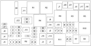
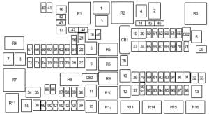
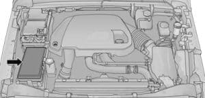
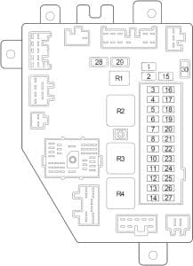
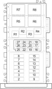
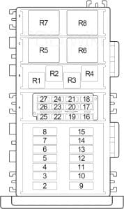
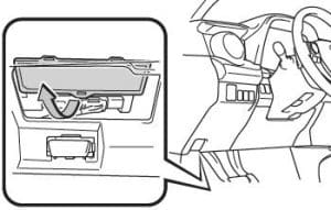
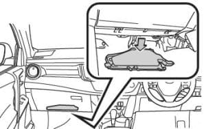
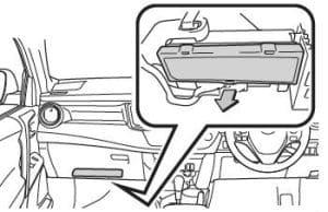
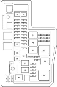
Passenger Compartment Fuse Box

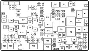
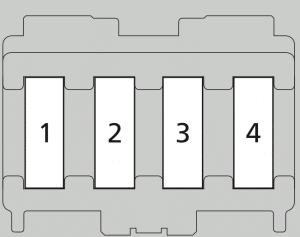
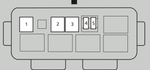
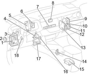
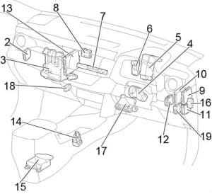
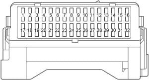
Ford F-150 – fuse box diagram passenger compartment

Fuse Number Fuse Rating Protected Component
1 Not used.
2 7.5A Memory module logic.

Memory seat switches.

Lumbar motor.

3 20A Driver door lock motor.
4 5A Trailer brake control.
5 20A Not used (spare).
6 10A Not used (spare).
7 10A Not used (spare).
8 10A Not used (spare).
9 10A Extended power module (base).
10 5A Embedded modem module.
11 5A Combined sensor module.
12 7.5A Climate head module.

Smart datalink connector.

13 7.5A Cluster.

Steering column control module.

14 10A Brake on/off switch.
15 10A Smart datalink connector.
16 15A Tailgate release.
17 5A Heads up display.

Terrain switch.

Ignition switch and passive-entry passivestart

start stop switch.

18 5A Key inhibit solenoid.
19 7.5A Extended power module (base).
7.5A Restraint control module (Raptor).
20 7.5A Not used (spare).
21 5A Heads up display.

In car temperature with humidity sensor.

22 5A Passenger occupant detection (Raptor).
23 10A Power driven rear glass switch.

Inverter.

Driver side window.

Moonroof.

Vista roof.

24 20A Central lock/unlock.
25 30A Driver door control module.
26 30A Passenger door control module.
27 30A Vista roof.

Moonroof.

28 20A Not used (spare).
29 30A Not used (spare).
30 30A Not used (spare).
31 15A Adjustable pedal switch and motor.
32 10A Multi-function display.

SYNC.

Radio frequency receiver.

33 20A Radio.
34 30A Run-start relay.
35 5A Selectable drive mode switch.

Upfitter switches (Raptor).

36 15A 360 camera module.

Heated steering wheel module.

Rear-view mirror.

Rear heated seats.

Lane departure warning module.

Automatic high beam module.

Image processing module A.

37 20A Not used (spare).
38 30A Circuit breaker. Rear window switches and motors.


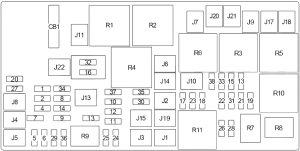
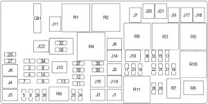
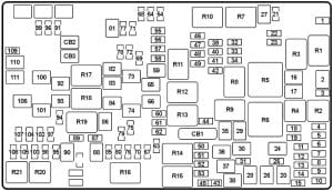
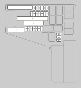
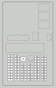
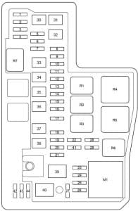
Engine compartment fuse box (2019-2020 (model year))

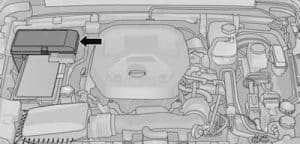
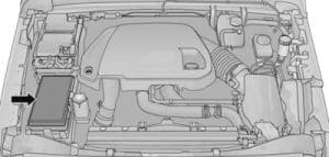
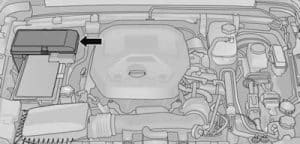
Ford F-150 – fuse box diagram – engine compartment

Fuse number Fuse rating Protected component
1 25A1 Horn.
2 50A2 Electric fan 1.
3 30A2 Windshield wiper motor.
4 60A2 Body control module.
5 30A2 Starter relay.
6 20A2 Power point 1.
8 20A2 Power point 2.
10 5A1 Rain sensor.
12 15A2 Upfitter 1 relay (Raptor).
13 10A1 4×4 run/start. 13 1
Adaptive cruise control run/start module.
14 Not used (base).
15A1 Not used (spare) (Raptor).
15 7.5A1 Front view camera. 15 1
Voltage quality module.
15A1 Voltage quality module (Raptor).
16 10A1 Powertrain control module.
Transmission control module run/start.
17 10A1 Anti-lock brakes run/start.
18 10A1 Electric power steering run/start.
19 5A1 Upfitter 5 relay (Raptor).
20 40A2 Blower motor.
21 30A2 Passenger seat motors.
22 20A1 Radio amplifier.
23 10A1 Alt A sensor.
24 30A2 Trailer brake control module.
25 50A2 Body control module 1.
26 50A2 Electric fan (Gas).
27 30A2 Driver seat motors/memory module.
28 15A1 Heated seat.
29 10A1 4×4 solenoid.
30 25A2 Trailer tow battery charge.
31 Not used.
32 10A1 A/C clutch.
33 Not used.
34 10A1 Vehicle power 5 (Diesel).
35 20A1 Vehicle power 4 (Gas).
15A1 Vehicle power 4 (Diesel).
36 10A1 Vehicle power 3.
37 25A1 Vehicle power 2 (Gas).
15A1 Vehicle power 2 (Diesel).
38 25A1 Vehicle power 1 (Gas).
20A1 Vehicle power 1 (Diesel).
39 Not used.
41 30A2 Body control module voltage quality
module feed.
43 20A2 Trailer tow lamps module.
45 Not used.
46 10A1 Steering column lock.
47 50A2 Powertrain control heater 3 (Diesel).
48 30A2 Fuel filter heater (Diesel).
49 Not used.
50 30A2 Fuel pump.
51 20A2 Power point 3.
52 50A2 Powertrain control heater 2 (Diesel).
53 25A2 Trailer tow park lamps.
54 Not used.
55 15A2 Upfitter 2 relay (Raptor).
56 Not used.
58 5A1 USB smart charger.
59 Not used.
60 Not used.
61 Not used (base).
15A1 Not used (spare) (Raptor).
62 5A1 Upfitter 6 relay (Raptor).
63 25A1 4×4.
64 15A1 E-locker.
65 Not used.
66 Not used.
67 Not used.
69 Not used.
70 40A2 Anti-lock brake system (ABS) valves.
Electric parking brake.
71 25A2 4×4.
72 Not used.
73 Not used.
74 10A1 Trailer tow backup lamps.
75 Not used.
76 40A2 Body control module 2.
77 30A2 Climate controlled seat.
78 10A1 Spot light module.
79 Not used.
80 10A1 Heated windshield wiper.

Upfitter 4 relay (Raptor).

81 Not used.
82 30A1 Transmission fluid pump.
5A1 Powertrain control module (Diesel).
83 15A1 Transmission control module.
84 Not used.
85 Not used.
86 Not used.
87 Not used.
88 10A1 Multi-contour seats relay.
Upfitter 3 relay (Raptor).
89 30A2 Power running boards.
91 Not used.
93 15A1 Heated mirrors.
94 15A1 Rear heated seat module (Raptor, Diesel).
95 Not used (base).
15A1 Not used (spare) (Raptor).
96 Not used.
97 40A2 Electric fan (Raptor).
50A2 Powertrain control heater 1 (Diesel).
98 15A2 10R transmission module r/s. 98 2
3.3L transmission fluid pump.
99 40A2 Heated rear window.
100 25A2 Diesel exhaust fluid (DEF) heater relay (Diesel).
101 25A2 Electric fan (base).
102 30A2 Power sliding back window.
103 20A2 Trailer tow stop-turn relay fuse.
104 15A1 Snowplow switch.
Rear heated seats (base).
105 10A1 Telescoping mirror.

1 Micro 2 fuse.

2 Slotted M case fuse.

Note: Spare fuse amperage may vary.

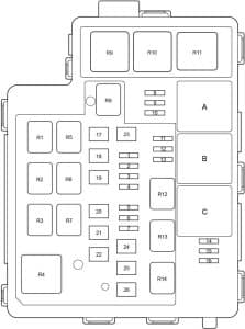
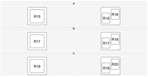
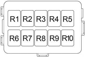
Relay Number Fuse Rating Protected Component
R02 Powertrain control module relay.
R05 Electric fan relay.

GMC Savana (2003 – 2007) – fuse box diagram

GMC Savana (2003 – 2007) – fuse box diagram

Year of  production: 2003, 2004, 2005, 2006, 2007

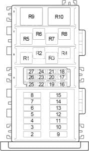
Passenger compartment relay box


No.
A
Circuit Protected
1  –
2 10 Outside Rearview Mirror Switch
3 15 Courtesy Lamp Relay
4 10 Left Rear Stop/Turn Signal
5 10 Cargo Unlock Relay
6 10 Right Rear Stop/Turn Signal
7 10 Driver Unlock Relay
8 10 Center High Mounted Stop Lamp (CHMSL), Cruise Control Module (CCM), Throttle Actuator Control Module (TCM (’06-’07)), Transmission Control Module (Diesel), Engine Control Module (Diesel)
9 10 HVAC Control Assembly, Air Temperature Actuator, HVAC Control Processor (’06-’07), Auxiliary Blower Motor Relays (’06-’07), Air/Mode Actuator (’06-’07)
10 20 HVAC Control Assembly, Vacuum Pump (Diesel)
11 10 Electronic Brake Control Module (EBCM), High Idle Switch (’06-’07), Traction Control Switch (’06-’07)
12 30 Rear Window Defogger Relay
13 30 Auxiliary Blower Motor Relays (Low/MED/High Speed)
14 10 Driver Turn Mirror
15 20 Door Lock Relay
16 10 Upfitter Park
17  –
18 10 Left Tail Lamp, License Lamp
19 10 Passengers Turn Mirror
20 10 Right Ttail Lamp
21 15 Trailer Park Lamp
22 10 Inflatable Restraint l/P Module Disable Switch, Front Park/Turn Signal Lamps, Front Marker Lamps
23 50 Upfitter Wiring Harness
20 Cooling Fan (SEO) (’03-’05)
60 Electronic Brake Control Module (EBCM) (’06-’07)
24 50 Auxiliary Relay (YF7)
20 Auxiliary Relay (SEO)
Circuit Breaker
CB1 25 Power Window (Driver/Front Passenger)
Relay 
R1 Rear Window Defogger
R2 Front Passenger Lock Actuator, LR/RR Door Lock Actuators
R3 Driver/Front Passenger/Cargo Lock Actuators, LR/RR Door Lock Actuators
R4 Auxiliary Relay
R5 Courtesy Lamp
R6 Cargo Unlock
R7 Driver Unlock
R8 Park Lamp
R9 Window Residual Accessory Power


Engine Compartment Fuse Box


No.
A
Protected Component
1 15 Radio, Vehicle Communication Interface Module (VCIM (’03-’05)), Chime Module (’06-’07)
2 20 Gasoline: Powertrain Control Module (PCM)
20 Diesel: Engine Control Module (ECM), Transmission Control Module (TCM), Coolant Heater
3 10 Trailer Stop/Turn Relay (Left)
4 10 Trailer Stop/Turn Relay (Right)
5 10 Back-Up Lamps Trailer or C405 (Cutaway)
6 10 Gasoline: Powertrain Control Module (PCM), Automatic Transmission, Body Control Module (BCM)
10 Diesel: Engine Control Module (ECM), Glow Plug Control Module (GPCM), Automatic Transmission, Body Control Module (BCM)
7 15 Stop Lamp Switch
8 20 Rear Window Defogger, Heated Mirror
9 10 Right Daytime Running Lamp/Turn Signal
10 10 Left Daytime Running Lamp/Turn Signal
11 15 Body Control Module (BCM)
12 20 Fuel Pump Relay
13 30 Trailer Wiring Harness
14 15 Turn Signal Hazard Flasher Module
15 15 Horn Relay
16 15 Body Control Module (BCM)
17 15 Trailer Stop/Turn Relay (Left and Right)
18 15 Body Control Module (BCM)
19 10 Body Control Module (BCM)
20 10 Remote Control Door Lock Receiver (RCDLR)
21 10 4.8L/5.3L/6.0L (Gasoline): Even Fuel Injectors, Even Ignition Coils
10 4.3L (Gasoline): Even Fuel Injectors, Ignition Coil
22 10 Stop Lamp Switch and A/C Relay
23 15 4.8L/5.3L/6.0L (Gasoline): Odd Fuel Injectors, Odd Ignition Coils, EVAP Canister Purge Solenoid, Mass Air Flow (MAF) Sensor, Park/Neutral Position (PNP) Switch
15 4.3L (Gasoline): Odd Fuel Injectors, Ignition Control Module, EVAP Canister Purge Solenoid, Mass Air Flow (MAF) Sensor, Park/Neutral Position (PNP) Switch
10 Diesel: MAF/IAT Sensor, Park/Neutral Position (PNP) Switch
24 10 Body Control Module (BCM)
25 20 Diesel: Fuel Heater
26 10 Inside Rearview Mirror
27 10 Crankcase, Powertrain Control Module (Gasoline), Engine Control Module (Diesel)
28 10 Brake Transmission Shift Interlock System
29 20 Auxiliary Power Outlet
30 15 Cigar Lighter, Data Link Connector (DLC)
31 10 Instrument Panel Cluster (IPC)
32 10 A/C Relay
33 30 Diesel: Engine Control Module (ECM)
34 10 EVAP Canister Vent Solenoid (Gasoline), Rear Fog Lamp Relay
35 10 Diesel: Cooling Fan Relay
36 15 Back-Up Lamps, Park/Neutral Position (PNP) Switch
37 10 Supplemental Inflatable Restraint System
38 15 Gasoline: Powertrain Control Module (PCM), Cruise Control Module (CCM), Throttle Actuator Control (TAC) Module, Steering WheelSpeed/Position Sensor
10 Diesel: Engine Control Module (ECM), Glow Plug Control Module (GPCM), Transmission Control Module
39 15 Gasoline: Oxygen Sensor
40 15 Gasoline: Oxygen Sensor
41 15 Windshield Wipers Relay
42 10 Right Headlamp (Low Beam)
43 10 Left Headlamp (Low Beam)
44 10 Left Headlamp (High Beam)
45 10 Right Headlamp (High Beam )
46 10 Body Control Module (BCM)
47 25 Windshield Wiper Motor
48 60 Electronic Brake Control Module (EBCM)
49 40 Starter Relay, Ignition Switch
50 30 Trailer Wiring Harness
51 40 Blower Motor Resistor
52 40 Ignition Switch
53 10 Diesel: Engine Control Module (ECM)
54  –
55 125 Fuse Block – Body
Circuit Breaker
CB1 30 Power Seat
Relay 
R1 Windshield Wiper
R2 Air Conditioning
R3 Rear Fog Lamp
R4 Headlamp (High Beam)
R5 Fuel Pump
R6 Headlamp (Low Beam)
R7 Horn
R8 Starter
R9 Diesel: Engine Control Module (ECM)


Auxiliary Fuse Box


No.
A
Circuit Protected
2 10 Dome Fluorescent Work Lamps
3 15 Access Panel Relays
4  –
Relay
1 Access Panel Latches (Left Side Rear)
5 Access Panel Latches (Left Side Front)
6 Access Panel Latches (Right Side)

WARNING: Terminal and harness assignments for individual connectors will vary depending on vehicle equipment level, model, and market.

Chevy G30 (1988 – 1992) – fuse box diagram

Chevy G30 (1988 – 1992) – fuse box diagram

Year of  production: 1988, 1989, 1990, 1991, 1992

Chevy G30 - fuse box diagram
Chevy G30 – fuse box diagram
No.
A
Circuit Protected
1 20 Horn, Glove Box Light, Clock, Electric/Vanity Mirrors, Cigarette Lighter
2 20 Parking Lights, Light Switch, Tail Lights
3 10 Electronic Control Module (ECM)
4 20 Gauge, Cruise Control, Ashtray Light
5 20 Ignition, Ignition Switch, Turn Signal Flasher, Back-Up Light Switch
6 10 Electronic Control Module (ECM), Ignition
7 10 Daytime Running Lights
8 5 Rear Air Conditioning Switch Light, Rear Auxiliary Heater Switch, Dome Light Switch, Cigarette Lighter, Convenience Tray Light, Foglight, Mirror Switch Light, Auxiliary Heater, Rear Air Conditioning
9 25 Auxiliary Heater and Air Conditioning
10 20 Heater, Air Conditioning
11 30 Circuit Breaker: Power Windows
12 20 Fuel Pump
13 30 Circuit Breaker: Power Seat, Power Door Locks
14 20 Hazard Flasher, Stop Lamps
15 10 Radio
16 25 Windshield Washer/Wiper Motor and Switch
17  –

WARNING: Terminal and harness assignments for individual connectors will vary depending on vehicle equipment level, model, and market.

Chevy G20 (1988 – 1992) – fuse box diagram

Chevy G20 (1988 – 1992) – fuse box diagram

Year of  production: 1988, 1989, 1990, 1991, 1992

Chevy G20 - fuse box diagram
Chevy G20 – fuse box diagram
No.
A
Circuit Protected
1 20 Horn, Glove Box Light, Clock, Electric/Vanity Mirrors, Cigarette Lighter
2 20 Parking Lights, Light Switch, Tail Lights
3 10 Electronic Control Module (ECM)
4 20 Gauge, Cruise Control, Ashtray Light
5 20 Ignition, Ignition Switch, Turn Signal Flasher, Back-Up Light Switch
6 10 Electronic Control Module (ECM), Ignition
7 10 Daytime Running Lights
8 5 Rear Air Conditioning Switch Light, Rear Auxiliary Heater Switch, Dome Light Switch, Cigarette Lighter, Convenience Tray Light, Foglight, Mirror Switch Light, Auxiliary Heater, Rear Air Conditioning
9 25 Auxiliary Heater and Air Conditioning
10 20 Heater, Air Conditioning
11 30 Circuit Breaker: Power Windows
12 20 Fuel Pump
13 30 Circuit Breaker: Power Seat, Power Door Locks
14 20 Hazard Flasher, Stop Lamps
15 10 Radio
16 25 Windshield Washer/Wiper Motor and Switch
17  –

WARNING: Terminal and harness assignments for individual connectors will vary depending on vehicle equipment level, model, and market.

GMC Vandura (1988 – 1992) – fuse box diagram

GMC Vandura (1988 – 1992) – fuse box diagram

Year of  production: 1988, 1989, 1990, 1991, 1992

GMC Vandura - fuse box diagram
GMC Vandura – fuse box diagram
No.
A
Circuit Protected
1 20 Horn, Glove Box Light, Clock, Electric/Vanity Mirrors, Cigarette Lighter
2 20 Parking Lights, Light Switch, Tail Lights
3 10 Electronic Control Module (ECM)
4 20 Gauge, Cruise Control, Ashtray Light
5 20 Ignition, Ignition Switch, Turn Signal Flasher, Back-Up Light Switch
6 10 Electronic Control Module (ECM), Ignition
7 10 Daytime Running Lights
8 5 Rear Air Conditioning Switch Light, Rear Auxiliary Heater Switch, Dome Light Switch, Cigarette Lighter, Convenience Tray Light, Foglight, Mirror Switch Light, Auxiliary Heater, Rear Air Conditioning
9 25 Auxiliary Heater and Air Conditioning
10 20 Heater, Air Conditioning
11 30 Circuit Breaker: Power Windows
12 20 Fuel Pump
13 30 Circuit Breaker: Power Seat, Power Door Locks
14 20 Hazard Flasher, Stop Lamps
15 10 Radio
16 25 Windshield Washer/Wiper Motor and Switch
17  –

WARNING: Terminal and harness assignments for individual connectors will vary depending on vehicle equipment level, model, and market.

Infiniti Q45 (2002 – 2006) – fuse box diagram

Infiniti Q45 (2002 – 2006) – fuse box diagram

Year of  production: 2002, 2003, 2004, 2005, 2006

Passenger Compartment

Infiniti Q45 - fuse box diagram - passenger compartment
Infiniti Q45 – fuse box diagram – passenger compartment
  1. Body Control Module (BCM)
  2. Fuse Box No.1
  3. ’02: Nissan Anti Theft System (NATS) Immobilizer
    ’03-’06: Shift Lock Control Unit
  4. Headlamp Battery Saver Control Unit
  5. Lane Departure Warning (LDW) Camera Unit
  6. Low Tire Pressure Warning Control Unit
  7. Combination Flasher Unit
  8. ’02-’04: Power Steering Control Unit
  9. Auto Air Conditioner Amplifier
  10. Engine Control Module (ECM)
  11. ’02-’04: Transmission Control Module (TCM)
  12. VDC/TCS/ABS Control Unit
  13. Fuse Box No.2
  14. Air Bag Diagnosis Sensor Unit
  15. Steering Lock Control Unit
  16. Driver Seat Control Unit
  17. ’02: Shift Lock Control Unit
    ’03-’06: Nissan Anti Theft System (NATS) Immobilizer
  18. ’02-’04: Automatic Speed Control Device (ASCD) Control Unit
  19. AV Control Unit

Passenger Compartment Fuse Box No. 1

Infiniti Q45 - fuse box diagram - passenger compartment fuse box no. 1
Infiniti Q45 – fuse box diagram – passenger compartment fuse box no. 1
No.
A
Circuit Protected
1 10 Body Control Module (BCM), Power Door Lock, Intelligent Cruise Control (ICC) Control Unit, ICC Warning Chime, ICC Brake Hold Relay, ICC Sensor, ICC Brake Switch, Headlamp Battery Saver Control Unit, AV and Navi Control Unit, TEL Adapter Unit, Theft Warning System, Nissan Anti Theft System (NATS) Immobilizer, Warning Chime, Lane Departure Warning (LDW) Switch, LDW Chime, LDW Camera Unit, Compass (Auto Anti-Dazzling Inside Mirror), Rear Window Defogger Relay, Dual Mode Meffler Control Unit, Power Window, Headlamp, Daytime Light System, Sunroof, Pre-Crash Seat Belt Control Unit, Power Seat, Climate Controlled Seat Relay, Rain Sensor, Trunk Lid Opener Relay
2 10 Auto Air Conditioner Amplifier, ECV Solenoid Valve (A/C Compressor)
3 10 Body Control Module (BCM), Power Door Lock, Trunk Lid Opener Relay, Trunk Lid Opener Switch, Theft Warning System, Warning Chime, Power Window, Reverse Interlock Door Mirror System, Headlamp, Daytime Light System, Sunroof, Power Seat
4 10 Rear Sunshade Unit, Rear Control Cancel Switch, Rear Control Cancel Relay, Handset, Door Mirror Defogger Relay, Auto Return Cancel Switch
5 10 Combination Flasher Unit
6 10 Data Link Connector, Combination Meter, Warning Chime, Auto Air Conditioner Amplifier, Headlamp Battery Saver Control Unit, Low Tire Pressure Warning Control Unit, Handset, Security Indicator Lamp, Body Control Module (BCM), Theft Warning System, Nissan Anti Theft System (NATS) Immobilizer, Steering Lock Control Unit, Clock, Active Damper Suspension Control Unit
7 10 VDC/TCS/ABS Control Unit, Active Damper Suspension Control Unit, Rear Active Steer (RAS) Control Unit
8 10 Map Lamp, Console Lamp, Rear Personal Lamp, Front Step Lamp, Rear Step Lamp, Vanity Mirror Lamp, Trunk Room Lamp, Foot Well Lamp, Homelink Universal Transceiver, Detention Switch (A/T), Shift Lock Control Unit, Microphone, Door Mirror Control Unit, Reverse Interlock Door Mirror System, Ignition Key Hole Illumination, Seat Memory Switch
9 10 Combination Meter, Back-Up Lamp Relay, Back-Up Lamp, A/T Device, Alternator, Transmission Control Module (TCM), AV and Navi Control Unit, Rear View Camera Unit, Reverse Interlock Door Mirror System
10 20 Rear Window Defogger Relay
11 20 Rear Window Defogger Relay
12 10 Automatic Speed Control Device (ASCD) Control Unit, ASCD Brake Switch
13 15 Engine Control Module (ECM), Injectors, Fuel Pump Relay
14 10 Starter, Daytime Light Control Unit, Body Control Module (BCM)
15 20 Trunk Lid Opener Actuator, Fuel Lid Opener Actuator, Trunk Lid Opener Relay, Body Control Module (BCM), Trunk Closure Control Unit, Auto Trunk Control Unit, Auto Trunk Buzzer, Auto Trunk Motor
16 10 Air Fuel Ratio Sensor
17 10 ’05-’06: Stop Lamp Switch, VDC/TCS/ABS Control Unit, Intelligent Cruise Control (ICC) Brake Hold Relay, ICC Control Unit, Shift Lock Control Unit, Active Damper Suspension Control Unit, Rear Active Steer (RAS) Control Unit
15 ’02-’04: Stop Lamp Switch, VDC/TCS/ABS Control Unit, Intelligent Cruise Control (ICC) Brake Hold Relay, ICC Control Unit, Shift Lock Control Unit, Active Damper Suspension Control Unit
18 10 Heated Oxygen Sensors
19 15 Shift Lock Solenoid, Shift Lock Control Unit
20 10 Air Bag Diagnosis Sensor Unit, Occupant Classification System
21 10 Audio Unit, Display, Satellite Radio Tuner, BOSE Amplifier, Auto Air Conditioner Amplifier, CD Auto Changer, Rear Control Cancel Relay, Rear Control Switch, Antenna Amplifier, AV and Navi Control Unit, Multifunction Switch, Voice Activated Control Module, TEL Adapter Unit, Low Tire Pressure Warning Control Unit, Body Control Module (BCM), Remote Keyless Entry System, Theft Warning System, Combination Meter, Rear View Camera Unit, Headlamp, Daytime Light System, Power Seat
22 15 Combination Flasher Unit
Infiniti Q45 - fuse box diagram - passenger compartment relay box
Infiniti Q45 – fuse box diagram – passenger compartment relay box
No.
Relay
R1 Accessory

Passenger Compartment Fuse Box No.2

Infiniti Q45 - fuse box diagram - passenger compartment fuse box no. 2
Infiniti Q45 – fuse box diagram – passenger compartment fuse box no. 2
No.
A
Circuit Protected
31 15 Blower Motor, Auto Air Conditioner Amplifier
32 10 Key Switch and Key Lock Solenoid, Power Window, Detention Switch (A/T), Body Control Module (BCM), Auto Trunk Control Unit, Nissan Anti Theft System (NATS) Immobilizer, Steering Lock Control Unit, Warning Chime, Engine Control Module (ECM) Relay (Intake Valve Timing Control Position Sensor, Mass Air Flow Sensor, Crankshaft Position Sensor, Camshaft Position sensor, EVAP Canister Purge Volume Control Solenoid Valve, EVAP Canister Vent Control Valve)
33 15 Blower Motor, Auto Air Conditioner Amplifier
34 20 Front Wiper Relay, Front Wiper Motor, Front Washer Motor, Intelligent Cruise Control (ICC) Control Unit
35 10 Transmission Control Module (TCM), A/T PV IGN Relay
36 15 Fuel Pump Relay, Fuel Pump Control Module (FPCM)
37 10 Handset
38
Infiniti Q45 - fuse box diagram - passenger compartment relay box
Infiniti Q45 – fuse box diagram – passenger compartment relay box
No.
Relay
R1 Blower
R2 Engine Control Module (ECM)
R3 Fuel Pump


Infiniti Q45 - fuse box diagram - passenger compartment
Infiniti Q45 – fuse box diagram – passenger compartment
  1. AV and Navi Control Unit
  2. BOSE Amplifier
  3. Rear View Camera Control Unit
  4. Antenna Amplifier
  5. Rear Sunshade Unit
  6. Fuel Pump Control Module (FPCM)
  7. ’02-’04: Dual Mode Muffler Control Unit
  8. Intelligent Cruise Control (ICC) Unit
  9. ’05-’06: Pre-Crash Seat Belt Control Unit
  10. Fuel Lid Opener Actuator
  11. Rear Shock Absorber Actuator (RH)
  12. ’05-’06: Dual Mode Muffler Control Unit
  13. Trunk Lid Opener Actuator
  14. ’05-’06: Trunk Closure Control Unit
  15. ’05-’06: Rear Active Steer (RAS) Control Unit
  16. Active Damper Suspension Control Unit
  17. ’05-’06: Satellite Radio Tuner
  18. Voice Activated Control Module
  19. Rear Shock Absorber Actuator (LH)
  20. ’03-’06: Auto Trunk Control Unit
  21. ’05-’06: TEL Adapter Unit

Engine Compartment

Infiniti Q45 - fuse box diagram - engine compartment
Infiniti Q45 – fuse box diagram – engine compartment
  1. Daytime Light Control Unit
  2. Fuse Box
  3. Front Shock Absorber Actuator (LH)
  4. VDC Actuator
  5. Front Shock Absorber Actuator (RH)
  6. Front Wiper Motor
  7. Relay Box No.2
  8. VDC Relay Box
  9. Hood Switch

Engine Compartment Fuse Box

Infiniti Q45 - fuse box diagram - engine compartment fuse box
Infiniti Q45 – fuse box diagram – engine compartment fuse box
No.
A
Circuit Protected
51 10 Air Conditioner Relay (Magnet Clutch), Engine Control Module (ECM)
52 15 Audio Unit, Satellite Radio Tuner, CD Auto Changer, AV and Navi Control Unit, Display, Voice Activated Control Module, AV and Navi Control Unit, Display, Voice Activated Control Module, TEL Adapter Unit, Low Tire Pressure Warning Control Unit, Rear View Camera Unit
53 20 Engine Control Module (ECM) Relay (Ignition Coils, Condenser, Intake Valve Timing Control Solenoid Valve, Vacuum Cut Valve Bypass Valve, Variable Induction Air Control System (VIAS) Control Solenoid Valve)
54 15 Tail Lamp Relay (Front/Rear Combination Lamps, Front/Rear Side Marker Lamp, License Lamps, Console Box Lamp, Glove Box Lamp, Illumination Control Switch, Illumination: (Cigarete Lighter, Multifunction Switch, VDC Off Switch, Hazard Switch, Audio Unit, CD Auto Changer, A/T Device, Clock, Climate Controlled Seat Temperature Dial, Headlamp Aiming Switch, AV and Navi Control Unit, Climate Controlled Seat Switch, Heated Seat Switch, Climate Controlled Seat Level Switch, Lane Departure Warning (LDW) Switch, Front/Rear Ashtrays, Rear Power Seat Switch, Rear Sunshade Front Switch, Active Dumper Suspension Select Switch, Door Control Unit, Power Window Main Switch, Microphone, Rear Console Cancel Switch), Headlamp Aiming Motor LH/RH, Headlamp Battery Saver Control Unit
55 20 Right Headlamp (Low Beam), Headlamp Relay No.1, Theft Warning System
56 15 Horn Relay, Steering Switch, Body Control Module (BCM), Theft Warning System, Alternator
57 20 Left Headlamp (Low Beam), Headlamp Relay No.1, Theft Warning System
58 10 Data Link Connector, Cooling Fan Relay No.2, Cooling Fan Relay No.3, Intake Valve Timing Control Solenoid Valve, Vacuum Cut Valve Bypass Valve, Variable Induction Air Control System (VIAS) Control Solenoid Valve
71 15 Climate Controlled Seat Relay (Driver Side)
72 15 Climate Controlled Seat Relay (Passenger Side)
73 15 Headlamp (High Beam), Lighting Switch, Headlamp Relay No.2, Combination Meter, Daytime Light Control Unit, Body Control Module (BCM), Theft Warning System, Headlamp Battery Saver Control Unit
74 15 Throttle Control Motor Relay
75 10 Transmission Control Module (TCM), A/T PV IGN Relay
76 20 Rear Active Steer (RAS) Motor Relay, RAS Control Unit
77 10 Intelligent Cruise Control (ICC) Unit
78 15 Frong Fog Lamp Relay
B 50 Ignition Relay (Fuse: “1”, “2”, “5”, “7”, “9”, “34”, “35”, “36”, “37”, “81”, “82”)
C 50 Accessory Relay (Fuse: “4”; Circuit Breaker No.3 – Cigar Lighter, Front Power Socket), Fuse: “3”, “6”, “8”, “10”, “11”, “15”, “17”, “19”, “22”
D 30 ’05-’06: Pre-Crash Seat Belt Control Unit
30 ’02: VDC/TCS/ABS
E 40 Cooling Fan Relay No.1
F 30 VDC/TCS/ABS (Solenoid Valve Relay)
G 50 Ignition Switch, Park/Neutral Position Switch, Starter, Accessory Relay
H 40 Circuit Breaker No.1 (Power Window, Door Lock, Driver Door Control Module, Rear LH Door Control Unit, Body Control Module(BCM), Sunroof Motor, Automatic Drive Positioner), Circuit Breaker No.2 (Power Window, Door Lock, Passenger Door Control Module, Rear RH Door Control Unit, Driver Seat Control Unit, Automatic Drive Positioner, Rear Power Seat Control Unit (LH/RH))
I 40 Cooling Fan Motor No.2 (Cooling Fan Relay No.1, Cooling Fan Relay No.2, Cooling Fan Relay No.3)
J 30 BOSE Amplifier
K 50 VDC/TCS/ABS (Motor Relay)
L 50 Blower Relay (Fuse: “31”, “33”), Fuse: “32”
Relay
R1 Back-Up Lamp
R2 Throttle Control Motor
R3 Headlamp (No.2)
R4 Headlamp (No.1)
R5 Park/Neutral Position
R6 Air Conditioner
R7 Tail Lamp
R8 Horn
R9 Ignition
R10 Front Wiper

Engine Relay Fuse Box

Infiniti Q45 - fuse box diagram - engine compartment relay box
Infiniti Q45 – fuse box diagram – engine compartment relay box
No.
A
Circuit Protected
81 20 Heated Seat (Front/Rear)
82 10 Daytime Light Control Unit
Relay
R1 ’05-’06: Cooling Fan (No.1)
’03-’04: Climate Controlled Seat
R2 ’05-’06: Intelligent Cruise Control (ICC) Brake Hold
R3 ’05-’06: Front Fog Lamp
R4 ’02-’04: Intelligent Cruise Control (ICC) Brake Hold
R5 ’05-’06: Front Wiper Rain
’02-’04: A/T PV ign


Infiniti Q45 - fuse box diagram - engine compartment relay box
Infiniti Q45 – fuse box diagram – engine compartment relay box
No.
Relay
R1 Cooling Fan (No.2)
R2  –
R3 Cooling Fan (No.3)

WARNING: Terminal and harness assignments for individual connectors will vary depending on vehicle equipment level, model, and market.

Infiniti Q45 (1997 – 2001) – fuse box diagram

Infiniti Q45 (1997 – 2001) – fuse box diagram

Year of  production: 1997, 1998, 1999, 2000, 2001

Passenger Compartment

Infiniti Q45 - fuse box diagram - passenger compartment
Infiniti Q45 – fuse box diagram – passenger compartment
  1. Transmission Control Module (TCM)
  2. Rear Window Defogger Relay
  3. Circuit Breaker No.2
  4. Door Mirror Defogger Relay
  5. Circuit Breaker No.1
  6. Super Multiple Junction (SMJ)
  7. Fuse Box
  8. Shift Lock Control Unit
  9. Automatic Speed Control Device (ASCD) Control Unit
  10. Automatic Speed Control Device (ASCD) Hold Unit
  11. Body Control Module (BCM)
  12. Auto Air Conditioner Amplifier
  13. Combination Flasher Unit
  14. Display and Navi Control Unit
  15. Power Steering Control Unit
  16. ABS/TCS Control Unit
  17. Throttle Actuator Control (TAC)
  18. Fog Lamp Relay
  19. Fuel Pump Relay No.1
  20. Engine Control Module (ECM) Relay
  21. ’00-’01: Fuel Pump Relay No.2
    ’97-’00: Throttle Motor Relay
  22. Engine Control Module (ECM)
  23. Air Bag Diagnosis Sensor Unit
  24. Driver’s Seat Control Unit
  25. Nissan Anti Theft System (NATS) Immobilizer
  26. Super Multiple Junction (SMJ)
  27. Super Multiple Junction (SMJ)

Passenger Compartment Fuse Box

Infiniti Q45 - fuse box diagram - passenger compartment fuse box
Infiniti Q45 – fuse box diagram – passenger compartment fuse box
1 15 Blower Motor
2 10 Data Link Connector, EVAP Canister Purge Control Valve, EVAP Canister Purge Control Solenoid Valve, Vacuum Cut Valve Bypass Valve, EGR Function, EGRC Solenoid Valve, MAP/BARO Switch Solenoid Valve, EVAP Canister Vent Control Valve, Cooling Fan, Power Steering Oil Pressure Switch, Intake Valve Timing Control Solenoid Valve
3 7.5 Heated Oxygen Sensor
4 7.5 Combination Meter
5  –
6 7.5 Air Conditioner
7 7.5 Receiver (Telephone), Handset
8 10 Audio Unit, CD Auto Changer, Power Antenna Timer and Motor, Display and Navi Control Unit
9 7.5 Door Mirror Defogger Relay, Door Mirror Remote Control Switch
10 7.5 Rear Sunshade Unit
11 20 Front Wiper Relay, Front Wiper Motor, Body Control Module (BCM), Front Wiper Switch, Front Washer Motor
12 10 Warning Chime, CD Auto Changer, Steering Wheel Receiver Control Switch, Receiver (Telephone)
13 10 Hazard Switch (Combination Flasher Unit), Multi-Remote Control Relay, Turn Indicator, Body Control Module (Hazard), Combination Switch (Turn Signal)
14 7.5 Body Control Module (BCM) (Headlamp, Power Window, Power Door Lock, Warning Chime, Interior Illumination Control, Rear Window Defogger, Sunroof), Vehicle Security Lamp Relay, Vehicle Security Horn Relay, Automatic Drive Positioner, Seat Memory Switch)
15 15 Blower Motor
16 7.5 Heated Oxygen Sensor
17 10 Air Bag Diagnosis Sensor
18 10 Park/Neutral Position Switch (Back-Up Lamp, Combination Meter, Tail Lamp Relay), Park/Neutral Position Switch, Display and Navi Control Unit
19 7.5 Hazard Switch (Combination Flasher Unit)
20 7.5 Daytime Light Control Unit
21 10 Heated Seat
22 7.5 Illumination Control Switch, Glove Box Lamp, Illumination: (Combination Meter, TCS Switch, Active Damper Suspension Select Switch, Audio Unit, Illumination Time Control Switch, Front/Rear Cigarette Lighter, Ashtray, Headlamp Aiming Switch, A/T Device, Power Window Main Switch, Auto Anti-Dazzling Inside Mirror, IVCS Switch, Driver’s Door Control Unit, Passenger Door Control Unit, Clock, A/C Control Unit, Hazard Switch, Telephone Switch, Rear Sunshade Switch)
23 7.5 Body Control Module (BCM) (Headlamp, Wiper, Interior Illumination Control, Multi-Remote Control System, Automatic Drive Positioner)
24 15 Front Cigarette Lighter, Front Power Socket
25  –
26 20 Trunk Lid Opener Actuator, Fuel Lid Opener Relay and Actuator, Trunk Lid and Fuel Lid Opener Switch, Multi-Remote Control System
27 10 Interior Lamp, Map Lamp, Console Lamp, Trunk Room Lamp, Vanity Mirror Lamp, Trunk Closure Control Unit, Body Control Module (BCM), Ignition Key Hole Illumination, Foot-Well Lamp, Rear Personal Lamp, Front/Rear Step Lamp, Homelink Transmitter, Vehicle Communication System (IVCS) Switch
28 10 Combination Meter, Key Switch, Body Control Module (BCM), Power Door Lock, Warning Chime, Clock, Power Antenna Timer and Motor, Trunk Closure Control Unit, Sunroof Relay, Multi-Remote Control System, Interior Illumination Control, Security Indicator, Automatic Drive Positioner, Detention Switch (Shift)
29 15 Injectors, Engine Control Module (ECM), Fuel Pump Control Module (FPCM)
30 10 Active Suspension, ABS/TCS, Power Steering Control Unit
31 7.5 ABS/TCS
32 7.5 Body Control Module (BCM) (Headlamp, Power Window, Interior Illumination Control, Warning Chime, Sunroof, Vehicle Communication System (IVCS), Automatic Drive Positioner), Rear Window Defogger Relay, Auto Anti-Dazzling Inside Mirror, Automatic Speed Control Device (ASCD) Hold Unit, ASCD Steering Switch, Nissan Anti Theft System (NATS) Immobilizer, Display and Navi Control Unit
33 15 ’97-’00: Fuel Pump Relay, Fuel Pump Control Module (FPCM)
34 7.5 Starter, Body Control Module (BCM), Daytime Light Control Unit, Vehicle Communication System (IVCS), Automatic Drive Positioner
35  –
36 20 Rear Power Socket (LH/RH)
37 15 Stop Lamp Switch, Stop and Tail Lamp Sensor, Automatic Speed Control Device (ASCD) Control Unit, Active Suspension, ABS/TCS
38 15 Rear Window Defogger Relay, Door Mirror Defogger Relay
39 15 Rear Window Defogger Relay, Auto Air Conditioner Amplifier
40 15 Fog Lamp Relay
Relay
R1 ’99-’01: Sunroof
R2 ’99-’01: Vehicle Security Lamp
’97-’98: Sunroof


Infiniti Q45 - fuse box diagram - passenger compartment fuse box
Infiniti Q45 – fuse box diagram – passenger compartment fuse box
No.
Relay
R1 Accessory
R2 Ignition
R3 Blower


Infiniti Q45 - fuse box diagram - passenger compartment
Infiniti Q45 – fuse box diagram – passenger compartment

* – 1997-2000

  1. Rear Shock Absorber Actuator (LH)
  2. Active Damper Suspension Control Unit (Left)
    Vehicle Communication System (IVCS) (Right)
  3. Rear Sunshade Unit
  4. Rear Shock Absorber Actuator (RH)
  5. Fuel Lid Opener Relay
  6. Throttle Motor Relay
  7. Audio Amplifier Relay
  8. Vehicle Security Horn Relay
  9. Multi-Remote Control Relay
  10. Fuel Lid Opener Actuator
  11. Stop and Tail Lamp Sensor (Left)
    Trunk Closure Control Unit (Right)
  12. Trunk Lid Opener Actuator
  13. Fuel Pump Control Module (FPCM)

Engine Compartment

Infiniti Q45 - fuse box diagram - engine compartment
Infiniti Q45 – fuse box diagram – engine compartment
  1. Cooling Fan Relay No.3
  2. Fuse Box
  3. Front Shock Absorber Actuator (RH)
  4. Wiper Motor
  5. ABS Actuator
  6. Vehicle Security Horn
  7. Automatic Speed Control Device (ASCD) Actuator
  8. Front Shock Absorber Actuator (LH)
  9. Hood Switch
  10. Daytime Light Control Unit

Engine Compartment Fuse Box

Infiniti Q45 - fuse box diagram - engine compartment fuse box
Infiniti Q45 – fuse box diagram – engine compartment fuse box
No.
A
Circuit Protected
51 15 ’00-’01: Fuel Pump Relay, Fuel Pump Control Module (FPCM)
52  –
53 15 Headlamp Relay (Right Headlamp, Low/High Beam (without Xenon), High Beam (Xenon), Lighting Switch, Daytime Light Control Unit, Fog Lamp Relay)
54 15 Headlamp Relay (Left Headlamp, Low/High Beam (without Xenon), High Beam (Xenon), High Beam Indicator, Lighting Switch, Daytime Light Control Unit)
55 7.5 Air Conditioner Relay
56 15 ABS/TCS
57 7.5 Engine Control Module (ECM), Data Link Connector, Nissan Anti Theft System (NATS) Immobilizer, Mass Air Flow Sensor, Camshaft Position Sensor, Ignition Coils, Variable Induction Air Control System (IACV-ACC), EVAP Canister Purge Control Solenoid Valve
58 15 Audio Unit, BOSE Amplifier, Audio Amplifier Relay, Vehicle Communication System (IVCS), Display and Navi Control Unit
59 20 Xenon: HID Relay (Right Headlamp (Low Beam))
60 10 Engine Control Module (ECM), Mass Air Flow Sensor, Camshaft Position Sensor, Ignition Coils, Variable Induction Air Control System (IACV-ACC), EVAP Canister Purge Control Solenoid Valve
61 20 Xenon: HID Relay (Left Headlamp (Low Beam))
62 7.5 Alternator
63 15 Tail Lamp Relay (Park Lamp, Tail Lamp, License Plate Lamp, Lighting Switch, Body Control Module (BCM), Headlamp Aiming Control, Fuse “22”)
64 15 Horn Relay, Steering Wheel Switch, Automatic Speed Control Device (ASCD) Steering Switch
B 80 Ignition Relay (Fuse: “4”, “6”, “7”, “18”, “19”, “20”, “21”, “30”, “31”, “32”), Fuse: “12”, “13”, “14”, “26”, “27”, “28”, “37”, “38”, “39”, “40”
C 80 Accessory Relay (Fuse: “9”, “10”, “11”, “23”, “24”, “36”), Blower Relay (Fuse: “1”, “15”)
D  –
E  –
F 40 ’99-’01: Cooling Fan
30 ’97-’98: Cooling Fan
G 30 Ignition Switch, Park/Neutral Position Switch, Starter
H 40 Circuit Breaker No.1 (Sunroof, Power Door Lock (Front), Power Window (Front)), Circuit Breaker No.2 (Power Seat, Power Door Lock (Rear), Power Window (Rear), Automatic Drive Positioner)
I 40 ’99-’01: Cooling Fan
30 ’97-’98: Cooling Fan
J 30 ABS/TCS
K 30 ABS/TCS
L  –
M  –
Battery +
A 120 Alternator, Fuse: “B”, “C”, “F”, “G”, “H”, “I”, “J”, “K”, “51”, “53”, “54”, “55”, “56”, “57”, “58”, “59”, “60”, “61”, “62”, “63”, “64”
Relay
R1 Cooling Fan (No.2)
R2 Front Wiper
R3 Horn
R4 Cooling Fan (No.1)
R5  –
R6 Xenon: High Intensity Discharge (HID) Lamp
Headlamp (without Xenon)
R7 Xenon: Headlamp
’97-’98: Vehicle Security Lamp
R8 Park/Neutral Position
R9 Tail Lamp

WARNING: Terminal and harness assignments for individual connectors will vary depending on vehicle equipment level, model, and market.

Nissan 300ZX (Z31 1984 – 1989) – fuse box diagram

Nissan 300ZX (Z31 1984 – 1989) – fuse box diagram

Year of  production: 1984, 1085, 1986, 1987, 1988, 1989

Passenger Compartment Fuse Box

Nissan 300ZX - fuse box - diagram- passeneger compartment fuse box
Nissan 300ZX – fuse box – diagram- passeneger compartment fuse box


RHD

Nissan 300ZX - fuse box diagram - passenger compartment RHD
Nissan 300ZX – fuse box diagram – passenger compartment RHD


LHD

Nissan 300ZX - fuse box diagram - passenger compartment LHD
Nissan 300ZX – fuse box diagram – passenger compartment LHD


No.
A
Protected Component
1 10 Right Headlight, Headlight System (’88-’89 US), Auxiliary Driving Switch (’88-’89 US), Theft Warning Control Unit (’88-’89 US), Passing Relay (except US), Rear Fog Relay (France)
2 10 Left Headlight, Headlight System (’88-’89 US), Passing Relay (except US), Rear Fog Relay (France)
3 15 Right Headlight Motor, Passing Relay (except US), Rear Fog Relay (except US)
4 15 Left Headlight Motor
5 15 US: Clearance Light, Illumination Lights, Taillight, License Lights, Headlight System
10 except US (LHD): Clearance Light, Illumination Lights, Taillight, Headlight Timer, Time Control Unit, Park Lamps (’87-’89)
15 RHD: Clearance Light, Illumination Lights, Taillight, License Lights, Rear Fog Relay, Front Fog Lamp Switch (’87-’89 Australia)
6 10 US: Interior Lights, Spot Lights, Step & Key Hole Lights, Luggage Compartment Light, Clock, Radio, Antenna Timer, Digital Meter, Steering Lock Switch, Time Control Unit (’84), Oxygen Sensor Amp (’84-’87), Chime (’88-’89), Auto Air Conditioner (’88-’89)
10 except US (LHD): License Lights, Rear Fog Lamps, Tail Lamps (’87-’89), Park Lamps (’87-’89)
10 RHD: Interior Lights, Spot Lights, Step Lights, Luggage Compartment Light, Digital Meter, Warning Chime, Clock, Audio, Power Antenna Timer (Digital Meter Model)
7 15 US: Auxiliary Driving Light
10 except US (LHD): Time Control Unit (’84-’86), Interior Lamps, Step Lamps, Spot Lamps, Luggage Lamp, Warning Chime, Clock, Audio
10 RHD: Rear Fog Lamps
15 ’87-’89 (Australia): Front Fog Lamps
8 10 Hazard Warning Lights
9 10 Horn, Time Control Unit (except EU, US: ’85-’89), Door Lock System (EU LHD)
10 20 ’85-’89 (US): Stoplight, Injector Cooling Fan Timer (’85-’87 Non-Turbo), A/T Interlock System (’88-’89)
15 ’84 (US): Stoplight, Injector Blower Motor
15 except US: Stoplight, Injector Blower Motor (except EU (LHD), except Australia)
11 15 Air Conditioner
12 15 Air Conditioner
13 15 Ignition Coil, EFI/ECCS System
14 10 Fuel Pump, EFI/ECCS System
15 10 Meter and Gauge, Time Control Unit, Hold Relay (US: ’84-’87), Oxygen Sensor Module (US: ’84-’87), Bulb Check Relay (US: ’85-’87 Non-Turbo), Dim-Dip Relay (Dim-Dip Lamp Model)
16 10 US: Turn Signal, Back-Up Light, Cruise Control, Receiver Amplifier, Boost Sensor (Turbo), Power Steering Switch (Non-Turbo), Voice Warning Unit (’84-’86), Injector Cooling Fan Timer (’84-’87 Turbo), Vacuum Pump (Turbo)
10 except US: Bulb Check Relay, Back-Up Light, Turn Signal, Boost Sensor, ASCD, Direction Sensor Amplifier (RHD – Digital Meter Mpdel), Cooling Fan (’84-’86, (’87-’89 EU RHD), Injector Blower Timer (’84-’86, (’87-’89 except EU LHD, Australia))
17 10 US: Kickdown Solenoid, Seat Belt Tension Reducer, Overdrive Switch, A/T Control Unit, Shock Absorber Control System, A/T Interlock Control Unit (’88-’89)
10 except US: A/T Control Unit
18 10 ’84-’86 (US): Door Lock System
10 ’87-’89 (US): Theft Warning Control Unit (’87-’89), Security Light (’88-’89)
20 ’84-’86 (except US – LHD): Bulb Check Relay
10 ’87-’89 (except US – LHD): Door Lock System
20 ’87-’89 (EU – LHD): Bulb Check Relay
20 RHD: Rear Window Defogger
19 10 ’84-’86 (US): Theft Warning Control Unit
10 ’87-’89 (US): Door Lock System
15 except US (LHD): Passing Lamp Relay
10 RHD: Door Lock System
20 10 Radio, Radio Amplifier (US), Clock, Time Control Unit (US, EU LHD), Remote Control Mirror (US, (LHD – ’87-’89)), Door Mirror Defogger (US), Theft Warning Control Unit (US), Power Antenna Switch (EU, RHD)
21 10 Rear Wiper & Washer, Headlight Washer, Digital Gauges (US, RHD)
22 15 Wiper & Washer
23 15 Cigarette Lighter
24 10 Air Conditioner
25  –
26  –
27  –
28 20 ’85-’89 (US – Turbo): Fan Motor, Bulb Check Relay
15 ’84 (US): Fan Motor
10 except US (LHD): ABS
20 ’84-’86 (RHD): Bulb Check Relay, Blower Motor, Differential Oil Cooler (Turbo)
15 ’84-’86 (RHD): Bulb Check Relay (Turbo except EU, Australia), Cooling Fan (Turbo except EU, Australia), Differential Oil Cooler (EU)
29 20 US: Rear Window Defogger
15 except US (LHD): Differential Oil Cooler (Turbo), Blower Motor (’84-’86)
15 except EU (LHD – ’87-’89): Bulb Check Relay, Condenser Fan (Turbo)
10 RHD: ABS
30 20 US: Rear Window Defogger
15 ’84-’86 (except US – LHD): Rear Window Defogger
20 ’87-’89 (except US – LHD): Rear Window Defogger
20 ’87-’89 (Australia, Hong-Kong, Singapore): Bulb Check Relay, Condenser Fan

Engine Compartment Relay Box

Nissan 300ZX - fuse box diagram - engine compartment relay box
Nissan 300ZX – fuse box diagram – engine compartment relay box
No.
Relay
R1 Vacuum Pump
R2 US: Compressor
except US (LHD): Passing Lamp
’87-’89 (RHD): Automatic Transmission
’87-’89 (RHD): Dim-Dip
R3 Turbo (US): Fan Motor
’85-’89 (US): Automatic Transmission
except US: Cooling Fan Motor
RHD: Cooling Fan Motor
R4 Headlamp Washer
R5 US: Auxiliary Driving Light
except US: Cooling Fan Motor (No.2)
R6 US: Theft Warning (No.1)
except US: Compressor
R7 Horn
R8 ASCD
R9 Bulb Check
R10 US: Theft Warning (No.2)
except US: Cooling Fan Motor (No.3)
R11 Inhibitor
’87-’89 (US – M/T): Interlock

Fusible Link Block

Nissan 300ZX - fuse box diagram - fusible link block
Nissan 300ZX – fuse box diagram – fusible link block

US

  • 84-’87: BR (BR) – EFI/ECCS System
  • ’84-’87: BR (R) – EFI/ECCS System
    ’88-’89: BR (R, BR) – EFI/ECCS System
  • G (L/B) – Power Seat (Circuit Breaker), Ignition Relay
  • BR (R) – Fuse No.: “1”, “2” (Headlight)
  • BR (W/L) – Ignition Switch

except US

  • BR (BR) – EFI/ECCS System (except ’87-’89 LHD)
  • BR (R) – EFI/ECCS System (except ’87-’89 LHD)
  • G (L/B) – Ignition Relay / BR (B/R) – ABS (’87-’89 except EU (LHD))
  • BR (R) – Combination Switch (Light)
  • BR (W/L) – Ignition Switch

Relay Location

  • ’88 (US): EFI Relay / Uphold Relay / Wiper Relay / Headlamp Timer / Headlamp Relay / Passing Relay
Nissan 300ZX - fuse box diagram - relay location EFI Relay / Uphold Relay / Wiper Relay / Headlamp Timer / Headlamp Relay / Passing Relay
Nissan 300ZX – fuse box diagram – relay location EFI Relay / Uphold Relay / Wiper Relay / Headlamp Timer / Headlamp Relay / Passing Relay


  • ’88 (US): Flasher Unit / Rear Window Defogger Relay / ASCD Control Unit / Ignition Relay / Blower Relay / Acceessory Relay
Nissan 300ZX - fuse box diagram - relay location (Flasher Unit / Rear Window Defogger Relay / ASCD Control Unit / Ignition Relay / Blower Relay / Acceessory Relay)
Nissan 300ZX – fuse box diagram – relay location (Flasher Unit / Rear Window Defogger Relay / ASCD Control Unit / Ignition Relay / Blower Relay / Acceessory Relay)


  • US: Fuel Pump Relay
Nissan 300ZX - fuse box diagram - relay location (Fuel Pump Relay)
Nissan 300ZX – fuse box diagram – relay location (Fuel Pump Relay)


  • except US (LHD): EFI Relay / Uphold Relay / Injector Blower Timer / Wiper Relay / Headlamp Relay/ Headlamp Timer / Passing Relay
Nissan 300ZX - fuse box diagram - relay location (EFI Relay / Uphold Relay / Injector Blower Timer / Wiper Relay / Headlamp Relay/ Headlamp Timer / Passing Relay)
Nissan 300ZX – fuse box diagram – relay location (EFI Relay / Uphold Relay / Injector Blower Timer / Wiper Relay / Headlamp Relay/ Headlamp Timer / Passing Relay)


  • RHD: EFI Relay / Uphold Relay / Injector Blower Timer / Wiper Relay / Headlamp Relay/ Headlamp Timer / Passing Relay
Nissan 300ZX - fuse box diagram - relay location (EFI Relay / Uphold Relay / Injector Blower Timer / Wiper Relay / Headlamp Relay/ Headlamp Timer / Passing Relay)
Nissan 300ZX – fuse box diagram – relay location (EFI Relay / Uphold Relay / Injector Blower Timer / Wiper Relay / Headlamp Relay/ Headlamp Timer / Passing Relay)


  • except US (LHD): Warning Chime / Rear Fog Relay / Ignition Relay No.1 & No.2 / F.P.C.M. Relay / Blower Relay / Accessory Relay / Flasher Unit
Nissan 300ZX - fuse box diagram - relay location (Warning Chime / Rear Fog Relay / Ignition Relay No.1 & No.2 / F.P.C.M. Relay / Blower Relay / Accessory Relay / Flasher Unit)
Nissan 300ZX – fuse box diagram – relay location (Warning Chime / Rear Fog Relay / Ignition Relay No.1 & No.2 / F.P.C.M. Relay / Blower Relay / Accessory Relay / Flasher Unit)


  • RHD: Warning Chime / Rear Fog Relay / Ignition Relay / Power Window Relay / F.P.C.M. Relay / Blower Relay / Accessory Relay / Flasher Unit
Nissan 300ZX - fuse box diagram - relay location (Warning Chime / Rear Fog Relay / Ignition Relay / Power Window Relay / F.P.C.M. Relay / Blower Relay / Accessory Relay / Flasher Unit)
Nissan 300ZX – fuse box diagram – relay location (Warning Chime / Rear Fog Relay / Ignition Relay / Power Window Relay / F.P.C.M. Relay / Blower Relay / Accessory Relay / Flasher Unit)


  • Power Antenna Timer / Differential Oil Cooler Relay No.1 & No.2 / Fuel Pump Relay
Nissan 300ZX - fuse box diagram - relay location (Power Antenna Timer / Differential Oil Cooler Relay No.1 & No.2 / Fuel Pump Relay)
Nissan 300ZX – fuse box diagram – relay location (Power Antenna Timer / Differential Oil Cooler Relay No.1 & No.2 / Fuel Pump Relay)

WARNING: Terminal and harness assignments for individual connectors will vary depending on vehicle equipment level, model, and market.

Nissan Leopard J Ferie (Y:32 1992 – 1997) – fuse box diagram

Nissan Leopard J Ferie (Y:32 1992 – 1997) – fuse box diagram

Year of  production: 1992, 1993, 1994, 1995, 1996, 1997

Passenger Compartment

Nissan Leopard J Ferie - fuse box diagram - passenger compartment
Nissan Leopard J Ferie – fuse box diagram – passenger compartment
  1. Transmission Control Module (TCM)
  2. Fuel Pump Relay
  3. Tail Lamp Relay
  4. Time Control Unit
  5. Super Multiple Junction (SMJ)
  6. Fuse Box
  7. Super Multiple Junction (SMJ)
  8. Door Lock Timer
  9. Stop Lamp Switch
  10. Automatic Speed Control Device (ASCD) Cancel Switch
  11. Theft Warning Relay
  12. Rear Door Switch Relay
  13. Auto-Air Conditioner Amplifier
  14. Super Multiple Junction (SMJ)
  15. Ignition Coil Relay
  16. Blower Relay (High Speed)
  17. Engine Control Module Relay (ECCS)
  18. Engine Control Module (ECCS)
  19.  –
  20. Air Bag Control Unit
  21. Tunnel Sensor and Safing Sensor
  22. Power Seat Control Unit
  23. Combination Flasher Unit
  24. Theft Warning Control Unit
  25. Kickdown Switch
  26. Shift LockControl Unit
  27. Automatic Speed Control Device (ASCD) Control Unit
  28. Power Steering Control Unit

Passenger Compartment Fuse Box

Nissan Leopard J Ferie - fuse box diagram - passenger compartment fuse box
Nissan Leopard J Ferie – fuse box diagram – passenger compartment fuse box
No. A
Circuit Protected
1 10 Hazard Switch (Combination Flasher Unit), Combination Switch (Turn Signal), Multi-Remote Control Relay No.1, Multi-Remote Control Relay No.2, Multi-Remote Control Unit
2 15 Audio Amplifier Relay
3 10 Telephone, Transceiver Unit
4 15 Stop Lamp Switch, Stop and Tail Lamp Sensor, Stop Lamps, Automatic Speed Control Device (ASCD) Control Unit, Shift Lock Control Unit
5 20 Front Wiper Motor, Time Control Unit, Wiper Relay, Front Wiper Switch, Front Washer Motor
6 15 Cigarette Lighter, Clock
7 7.5 Time Control Unit, Wiper Relay, Front Wiper Switch
8 10 Door Mirror Remote Control Switch, Theft Warning Control Unit
9 10 CD Player and Radio, Power Antenna Timer and Motor, Telephone (Receiver Control Unit)
10 15 Blower Motor
11 15 Blower Motor
12 10 Key Switch, Door Lock Timer, Multi-Remote Control Unit, Time Control Unit
13 7.5 Combination Meter, Theft Warning Control Unit, Clock, CD Player and Radio, Power Antenna Timer and Motor, Multi-Remote Control Unit, Warning Chime, Time Control Unit
14 15 Audio Amplifier Relay
15 20 Power Window Amplifier (Passenger Side)
16 20 Rear Power Window Amplifier (Right)
17  –
18  –
19 7.5 ’93-’95: Data Link Connector, Engine Control Module (ECM), Automatic Speed Control Device (ASCD) Control Unit, Heated Oxygen Sensors, Idle Air Control Valve (IACV-ACC) Valve, Idle Air Control Valve (IACV-FICD) Valve, Variable Timing Control (VTC) Solenoid Valve, Pressure Regulator Vacuum Relief (PRVR) Solenoid Valve
15 ’96-’97: Data Link Connector, Engine Control Module (ECM), Automatic Speed Control Device (ASCD) Control Unit, Air Fuel Ratio Sensors, Heated Oxygen Sensors, Idle Air Control Valve (IACV-ACC) Valve, Idle Air Control Valve (IACV-FICD) Valve, Variable Timing Control (VTC) Solenoid Valve, Pressure Regulator Vacuum Relief (PRVR) Solenoid Valve
20 7.5 Theft Warning Control Unit, Theft Warning Starter Relay, Daytime Light Control Unit, Sunroof Relay, Power Window Main Switch
21 7.5 Hazard Switch (Combination Flasher Unit)
22 7.5 Auto-Air Conditioner Amplifier
23 7.5 Interior Lamp, Trunk Room Lamp, Spot Lamp, Foot-Well Lamps, Step Lamps, Door Switches, Multi-Remote Control Unit, Vanity Mirror Lamps, Lighting Switch, Rear Door Switch Relay, Trunk Room Lamp Switch, Time Control Unit, Ignition Key Hole Illumination, Theft Warning Control Unit
24 7.5 Starter Relay, Engine Control Module (ECM), Theft Warning Starter Relay, Daytime Light Relay, Daytime Light Control Unit, Parking Brake Switch
25 7.5 Lighting Switch, Daytime Light Control Unit, Stop and Tail Lamp Sensor, Tail Lamps, Stop Lamps, Side Marker Lamps, License Plate Lamps, Clearance Lamps, Time Control Unit
26 7.5 Glove Box Lamp, Illumination Control Switch, Illumination: (Combination Meter, Cigarette Lighter, Push Control Unit, Hazard Switch, Clock, CD Player, and Radio, Power Window Main Switch, Power Window Switch (Passenger Side), Automatic Speed Control Device (ASCD) Main Switch, A/T Indicator, Auto Anti-Dazzling Inside Mirror, Rear Power Window Switch)
27 20 Rear Power Window Amplifier (Left)
28 3 Telephone, Transceiver Unit, Hand Set
29 10 Air Bag Control Unit
30 7.5 Inhibitor Switch (Back-Up Lamps, Transmission Control Module (TCM), Park/Neutral Position Relay), Automatic Speed Control Device (ASCD) Main Switch, ASCD Hold Relay, ASCD Cancel Switch, ASCD Control Unit, Fuel Pump Relay
31 7.5 Combination Meter, Door Switch, Rear Door Switch Relay, Auto Anti-Dazzling Inside Mirror
32 7.5 High Capacity Actively Controlled Steering (HICAS), Time Control Unit, Auto Air Conditioner Amplifier, Rear Window Defogger Relay
33 15 Heated Seat
34 15 Trunk Lid Opener Actuator, Fuel Lid Opener Actuator
35  –
36 20 Door Mirror Defogger Relay, Rear Window Defogger Relay, Time Control Unit, Auto Air Conditioner Amplifier
37 10 Shift Lock Control Unit
Nissan Leopard J Ferie - fuse box diagram - passenger compartment relay box
Nissan Leopard J Ferie – fuse box diagram – passenger compartment relay box
No.
Relay
R1 Accessory (No.2)
R2 Accessory (No.1)
R3 Ignition
Circuit Breaker
CB1
Power Seat
CB2
Power Window, Sunroof, Power Seat, Power Door Lock
Nissan Leopard J Ferie - fuse box diagram - passenger compartment
Nissan Leopard J Ferie – fuse box diagram – passenger compartment
  1. ABS Control Unit
  2. Stop and Tail Lamp Sensor
  3. Remote Control Unit
  4. High Capacity Actively Controlled Steering (HICAS) Control Unit

Engine Compartment

Nissan Leopard J Ferie - fuse box diagram - engine compartment
Nissan Leopard J Ferie – fuse box diagram – engine compartment
  1. Theft Warning Horn
  2. Hood Switch
  3. Wiper Motor
  4. ABS Actuator
  5. Daytime Light Control Unit
  6. Front Crash Zone Sensor
  7. Fuse Box

Engine Compartment Fuse Box

Nissan Leopard J Ferie - fuse box diagram - engine compartment fuse box
Nissan Leopard J Ferie – fuse box diagram – engine compartment fuse box
No.
A
Circuit Protected
51 15 Right Headlamp, Headlamp Control Unit, High Beam Indicator, Daytime Light Control Unit, Theft Warning Control Unit, Theft Warning Relay
52 15 Left Headlamp, Headlamp Control Unit, Daytime Light Control Unit, Theft Warning Relay
53  –
54  –
55 15 Horn Relay, Automatic Speed Control Device (ASCD) Steering Switch, Theft Warning Control Unit
56 15 Tail Lamp Relay (Lighting Switch, Fuse: “25”, “26”)
57 20 ABS
58 7.5 Engine Control Module (ECCS), Ignition Coil Relay, Mass Air Flow Sensor, Camshaft Position Sensor
59 10 Injectors
60 15 Fuel Pump Relay
61 20 Ignition Switch, Starter Hold Relay
62 10 Alternator
63 20 Rear Window Defogger Relay, Door Mirror Defogger Relay
64 20 Rear Window Defogger Relay, Door Mirror Defogger Relay
70  –
A 100 Alternator, Fuse: “E”, “F”, “55”, “56”, “63”, “64”
B 25 Cooling Fan
C 30 ABS
D 30 Starter Relay, Starter Hold Relay, Theft Warning System, Inhibitor Switch
E 45 Circuit Breaker (CB1), Circuit Breaker (CB2), Accessory Relay No.2 (Fuse: “11”, “10”), Fuse: “15”, “16”, “27”
F 75 Accessory Relay No.1 (Fuse: “5”, “6”, “7”, “8”), Ignition Relay (Fuse: “20”, “21”, “22”, “31”, “32”, “33”, “36”, “37”), Fuse: “1”, “2”, “3”, “4”, “12”, “13”, “14”, “23”, “34”
Relay
R1 Cooling Fan
R2 Automatic Speed Control Device (ASCD) Hold
R3 Daytime Light Cut
R4 Horn
R5 Wiper
R6 Park/Neutral Position
R7 Starter
R8 Rear Window Defogger
R9 Door Mirror Defogger
R10 ’96-’97: Starter Hold
R11 Air Conditioner

WARNING: Terminal and harness assignments for individual connectors will vary depending on vehicle equipment level, model, and market.

Infiniti Q45 (1990 – 1996) – fuse box diagram

Infiniti Q45 (1990 – 1996) – fuse box diagram

Year of  production: 1990, 1991, 1992, 1993, 1994, 1995, 1996

Passenger Compartment

1990 – 1993

Infiniti Q45 - fuse box diagram - passenger compartment
Infiniti Q45 – fuse box diagram – passenger compartment

1994 – 1996

Infiniti Q45 – fuse box diagram – passenger compartment
  1. Circuit Breaker (Power Door Lock, Power Seat)
  2. Combination Flasher Unit
  3. Accessory Relay No.2
  4. Accessory Relay No.1
  5. Ignition Relay No.1
  6. Fuse Box
  7. Transmission Control Module (TCM)
  8. ’90-’93: Door Lock Timer No.1
  9. ’90-’93: Power Window Relay
  10. Rear Window Defogger Relay
  11. Circuit Breaker (Power Window, Sunroof)
  12. ’90-’93: Time Control Unit
  13. Shift Lock Control Unit
  14. Headlamp Sensor
  15. Ignition Relay No.2
  16. ’90-’94: Theft Warning Horn Relay
  17. ’90-’93: Automatic Drive Positioner Control Unit
  18. Stop Lamp Switch
  19. Automatic Speed Control Device (ASCD) Brake Switch
  20. Kickdown Switch
  21. Resistor (Alternator)
  22. Automatic Speed Control Device (ASCD) Control Unit
  23. Power Steering Control Unit
  24. Blower Motor Relay (High Speed)
  25. ’90-’93: Theft Warning Control Unit
  26. ’90-’93: ABS Control Unit or TCS Control Unit
  27. Audio Amplifier Relay
  28. Engine Control Module (ECM) Relay
  29. ’90-’94: Ignition Coil Relay
  30. ’90-’95: Theft Warning Horn Relay No.2
  31. Engine Control Module (ECM)
  32. ’90-’93: Door Lock Relay
  33. Right Power Seat Control Unit
  34. Speed Sensor (Rear Extension)
  35. Air Bag Control Unit
  36. ’90-’93: Door Lock Timer No.2
  37. ’90-’94: Tunnel Sensor and Safing Sensor
  38. Left Power Seat Control Unit
  39. ’90-’93: Power Window Amplifier
  40. ’94-’96: Fog Lamp Relay
  41. ’94-’96: Courtesy Lamp relay
  42. ’94-’96: Sunroof Relay
  43. ’94-’96: Multi-Remote Control Relay
  44. ’94-’96: Multi-Remote Control Check Relay
  45. ’94-’96: Body Control Module (BCM)
  46. ’96: Automatic Speed Control Device (ASCD) Hold Relay
  47. ’94-’96: Throttle Control Module (TCM)
  48. ’94-’96: Auto Air Conditioner Amplifier
  49. ’96: Theft Warning Relay No.3

Passenger Compartment Fuse Box

Infiniti Q45 - fuse box diagram - passenger compartment box
Infiniti Q45 – fuse box diagram – passenger compartment box
No. A
Circuit Protected
1 10 ’94-’96: ABS/TCS
10 ’90-’93: Inhibitor Switch (Back-Up Lamps), Transmission Control Module (TCM), TCS Control Unit, Theft Warning System, Parn/Neutral Position Switch
2 10 ’94-’96: Inhibitor Switch (Back-Up Lamps), Transmission Control Module (TCM), TCS Control Unit, Automatic Speed Control Device (ASCD) Control Unit, Theft Warning Relay No.3, Parn/Neutral Position Switch
10 ’90-’93: Air Conditioner, Daytime Light Control Unit
3 15 ’94-’96: Fuel Pump Relay, Fuel Pump Control Module (FPCM)
10 ’90-’93: Receiver (Telephone), Handset
4 15 ’95-’96: Heated Oxygen Sensors, Air Fuel Ratio Sensors, Idle Air Control Valve Solenoid Valve, EGR Volume Control Valve
10 ’94: High Capacity Actively Controlled Steering (HICAS) Control Unit
15 ’90-’93: Blower Motor
5 10 ’94-’96: Air Bag Control Unit
15 ’90-’93: Blower Motor
6 20 ’90-’93: Wiper Motor, Wiper Switch, Washer Motor, Wiper Amplifier, Time Control Unit
7 15 ’94-’96: Blower Motor
10 ’90-’93: Engine Control Module (ECM), High Capacity Actively Controlled Steering (HICAS)
8 15 ’94-’96: Blower Motor
15 ’90-’93: Fuel Pump Relay, Fuel Pump Control Module (FPCM)
9 10 Radio, CD Auto Changer, Power Antenna Timer
10 10 Body Control Module (BCM), Door Mirror Control Unit, Diagnostic Information Display Control Unit, Automatic Drive Positioner
11 20 Rear Cigarette Lighter (Left and Right)
12 15 Cigarette Lighter
13 10 ’94-’96: Daytime Light Cancel Relay, Daytime Light Control Unit, Air Conditioner, Cooling Fan
15 ’90-’93: Stop Lamp Switch, Stop and Tail Lamp Sensor, Diagnostic Information Display Control Unit, Automatic Speed Control Device (ASCD) Control Unit, Active Suspension, Power Steering System, High Capacity Actively Controlled Steering (HICAS) Control Unit
14 20 ’94-’96: Rear Window Defogger Relay
10 ’90-’93: Radio, CD Auto Changer, Power Antenna Timer, Clock, Diagnostic Information Display Control Unit, Steering Receiver (Telephone), Power Seat, Key Hole Illumination, Air Bag Control Unit, TCS Control Unit, High Capacity Actively Controlled Steering (HICAS) Control Unit, Auto Air Conditioner Amplifier, Automatic Drive Positioner
15 20 Rear Window Defogger Relay
16 10 ’94-’96: Receiver (Telephone), Handset
20 ’90-’93: Rear Window Defogger Relay
17 20 ’94-’96: Audio Amplifier Relay
15 ’90-’93: Active Suspension
18 15 ’94-’96: Stop Lamp Switch, Stop and Tail Lamp Sensor, Diagnostic Information Display Control Unit, Automatic Speed Control Device (ASCD) Control Unit
20 ’90-’93: Audio Amplifier Relay
19 10 ’94-’96: Body Control Module (BCM), Key Switch, Power Door Lock, Warning Chime, Automatic Drive Positioner
20 10 ’94-’96: Body Control Module (BCM), Power Seat, Power Window, Key Hole Illumination
10 ’90-’93: Combination Meter, Data Link Connector, Diagnostic Information Display Control Unit, Warning Chime, Seat Belt, Automatic Drive Positioner, Rear Window Defogger Relay, Auto Anti-Dazzling Inside Mirror, Power Door Lock, Time Control Unit, Power Steering System, TCS
21 10 ’94-’96: Radio, CD Auto Changer, Power Antenna Timer, Clock, Diagnostic Information Display Control Unit, Steering Receiver (Telephone), Front Power Window (RH), Rear Power Window, Multi-Remote Control Unit, Key Hole Illumination, Air Conditioner
10 ’90-’93: Hazard Switch (Combination Flasher Unit), Multi-Remote Control Relay, Multi-Remote Control Check Relay, Turn Signal Switch, Turn Indicator, Multi-Remote Control Unit
22 10 ’94-’96: Fuel Filler Lid Opener Actuator, Trunk Lid Opener Actuator, Multi-Remote Control Unit
10 ’90-’93: Air Bag Control Unit
23 10 ’94-’95: Active Suspension
15 ’90-’93: Shift Lock System, Key Switch
24 10 ’94-’96: ’96: Hazard Switch (Combination Flasher Unit)
10 ’90-’93: Receiver (Telephone), Handset
25 10 ’94-’96: Combination Meter, Data Link Connector, Alternator Resistor, Diagnostic Information Display Control Unit, Body Control Module (BCM), Warning Chime, Seat Belt, Automatic Drive Positioner, Buckle Switch, Door Switch, Sunroof Relay, Rear Window Defogger Relay, Auto Anti-Dazzling Inside Mirror, Power Door Lock
10 ’90-’93: Fuel Filler Lid Opener Actuator, Trunk Lid Opener Actuator
26 10 Combination Meter, Automatic Speed Control Device (ASCD) Main Switch, ASCD Hold Relay, ASCD Control Unit, Park/Neutral Position Relay, Engine Control Module (ECM)
27 15 ’90-’95: Active Suspension
28 15 ’94-’96: Heated Seat, Power Seat (LH/RH)
10 ’90-’93: High Capacity Actively Controlled Steering (HICAS), Speedometer
29 20 ’94-’96: Wiper Motor, Wiper Switch, Washer Motor, Wiper Amplifier, Body Control Module (BCM)
10 ’90-’93: ABS
30 15 ’95-’96: Injectors
10 ’90-’93: Clearance Lamps, Side Marker Lamps, Tail Lamps, License Plate Lamps, Stop and Tail Lamp Sensor, Headlamp Relay Unit, Lighting Switch, Glove Box Lamp, Body Control Module (BCM), Warning Chime, Illumination Control Switch, Illumination: (Combination Meter, Ashtray, Automatic Speed Control Device (ASCD) Main Switch, Rear Window Defogger Switch, Cigarette Lighter, TCS Switch, Power Window Main Switch, 1ST Position Switch, Air Conditioner Switch Panel, Hazard Switch, Clock, Door Mirror Switch, Radio, Heated Seat Switch, Auto Anti-Dazzling Inside Mirror, Power Window Switch)
Relay
R1 Accessory (No.2)
R2 Accessory (No.1)
R3 Ignition (No.1)
Infiniti Q45 – fuse box diagram – passenger compartment box
  1. TCS Control Unit or ABS Control Unit
  2. ’90-’93: Rear Amplifier (Audio)
    ’94-’96: Multi-Remote Control Unit
  3. Fuel Pump Control Module (FPCM)
  4. ’90-’94: High Capacity Actively Controlled Steering (HICAS) Control Unit
  5. ’90-’95: Active Suspension Control Unit
  6. Fuel Pump Relay
  7. Power Antenna Timer
  8. ’94-’96: CD Auto Changer
  9. ’90-’93: Courtesy Lamp Relay
  10. Stop and Tail Lamp Sensor

Engine Compartment

1990 – 1993

Infiniti Q45 - fuse box diagram - engine compartment
Infiniti Q45 – fuse box diagram – engine compartment

1994 – 1996

Infiniti Q45 - fuse box diagram - engine compartment
Infiniti Q45 – fuse box diagram – engine compartment
  1. ’94-’96: Cooling Fan Relay
  2. Battery
  3. Headlamp Relay Unit
  4. Fuse Box
  5. Wiper Amplifier
  6. Starter Relay
  7. Wiper Motor
  8. ABS Actuator
  9. Automatic Speed Control Device (ASCD) Actuator
  10. ASCD Pump
  11. ’94-’96: Daytime Light Cancel Relay
  12. ’94-’96: TCS Relay
  13. ’94-’96: Daytime Light Control Unit
  14. ’90-’93: Dropping Resistor
  15. ’90-’95: Power Transistor Unit (Left)
  16. ’90-’92: Left Crash Zone Sensor
  17. ’90-’95: Power Transistor Unit (Right)
  18. ’90-’94: Center Crash Zone Sensor
    ’92-’93: Cooling Fan Relay
  19. ’90-’92: Right Crash Zone Sensor

Engine Compartment Fuse Box

Infiniti Q45 - fuse box diagram - engine compartment
Infiniti Q45 – fuse box diagram – engine compartment
Infiniti Q45 - fuse box diagram - engine compartment fuse box
Infiniti Q45 – fuse box diagram – engine compartment fuse box
No.
A
Circuit Protected
31 15 Right Headlamp, Headlamp Relay Unit, Daytime Light Control Unit, Lighting Switch, Theft Warning Relay No.1, Body Control Module (BCM)
32 15 Left Headlamp, Headlamp Relay Unit, Daytime Light Control Unit, Fog Lamp Relay, Lighting Switch, Theft Warning Relay No.1
33 15 ’94-’96: Horn Relay, Automatic Speed Control Device (ASCD) Steering Switch, Body Control Module (BCM)
10 ’90-’93: Horn Relay, Theft Warning System
34 10 Hazard Switch (Combination Flasher Unit), Multi-Remote Control Relay, Multi-Remote Control Check Relay, Turn Signal Switch, Turn Indicator, Multi-Remote Control Unit
35 10 ’96: Theft Warning Relay No.2 (Horn), Automatic Speed Control Device (ASCD) Steering Switch, Body Control Module (BCM)
36 10 ’94-’96: Alternator
37 10 ’94-’96: Clearance Lamps, Side Marker Lamps, Tail Lamps, License Plate Lamps, Stop and Tail Lamp Sensor, Headlamp Relay Unit, Lighting Switch, Glove Box Lamp, Body Control Module (BCM), Warning Chime, Illumination Control Switch, Illumination: (Combination Meter, Ashtray, Automatic Speed Control Device (ASCD) Main Switch, Rear Window Defogger Switch, Cigarette Lighter, TCS Switch, Power Window Main Switch, 1ST Position Switch, Air Conditioner Switch Panel, Hazard Switch, Clock, Door Mirror Switch, Radio, Heated Seat Switch, Auto Anti-Dazzling Inside Mirror, Power Window Switch)
15 ’90-’93: Headlamp Relay Unit
38 10 Interior Lamp, Trunk Room Lamp, Foot Lamps, Spot Lamps, Key Illumination, Courtesy Lamp Relay (Courtesy Lamps), Body Control Module (BCM), Illumination Control Switch, Door Switch, Combination Meter (Chime)
39 15 ’94-’96: Fog Lamp Relay
40 10 Theft Warning Relay No.2 (Starter), Starter Relay, Daytime Light Cancel Relay, Daytime Light Control Unit, Parking Brake Switch, Engine Control Module (ECM)
41 10 ’94-’96: Receiver (Telephone)
10 vAlternator
42 20 TCS
43 20 ABS/TCS
A 120 Alternator, Fuse: “D”, “G”, “M”, “36”
B  –
C 100 Fuse: “14”, “15”, “31”, “32”, “33”, “34”, “35”, “37”, “38”
D 30 Accessory Relay No.2 (Fuse: “7”, “8”)
E 30 ABS/TCS
F 25 Circuit Breaker (Power Window, Sunroof), Circuit Breaker (Power Door Lock, Power Seat)
G 75 Accessory Relay No.1 (Fuse: “10”, “11”, “12”, “29”), Ignition Relay No.1 (Fuse: “13”, “16”, “24”, “25”, “26”), Ignition Relay No.2 (Fuse: “1”, “2”, “28”), Fuse: “E”, “F”, “J”, “17”, “18”, “19”, “20”, “21”, “22”, “41”, “42”, “43”
H  –
I 30 Ignition Switch, Starter Relay, Inhibitor Switch, Fuel Pump Relay, Fuel Pump Control module (FPCM)
J 30 TCS
K 25 Engine Control Module (ECM), Transmission Control Module (TCM), Mass Air Flow Sensor, Data Link Connector, Camshaft Position Sensor (CMPS)
L 25 ’96: Body Control Module (BCM), Automatic Drive Positioner
25 ’90-’94: Engine Control Module (ECM)
M 30 ’92-’96: Cooling Fan
25 ’90-’91: Cooling Fan
Relay
R1 Air Conditioner
R2 Park/Neutral Position
R3 ’90-’95: Automatic Speed Control Device (ASCD) Hold
’96: Theft Warning (No.2)
R4 Cooling Fan
R5 Theft Warning (No.1)
R6 Horn

WARNING: Terminal and harness assignments for individual connectors will vary depending on vehicle equipment level, model, and market.