Dodge RAM 1500 (2002 – 2005) – fuse box diagram
Year of production: 2002, 2003, 2004, 2005
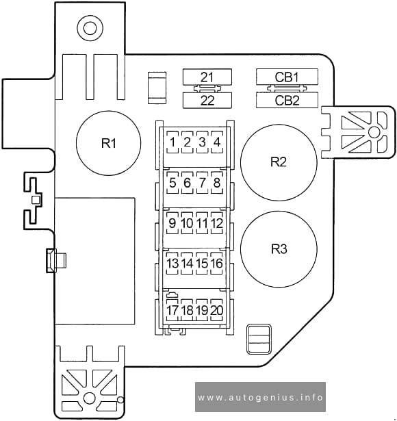
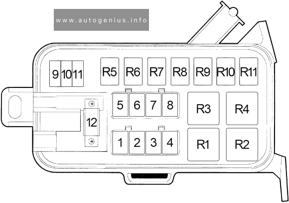
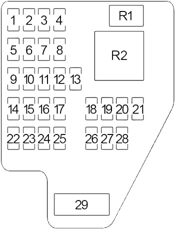
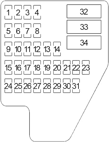
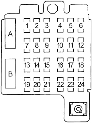
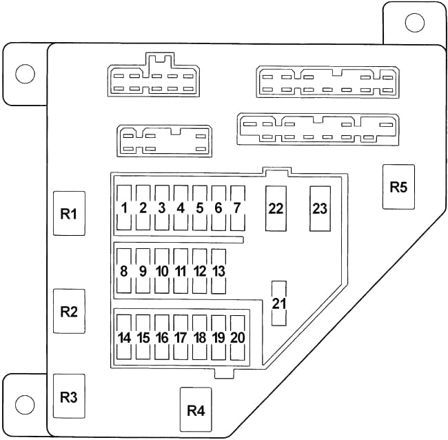
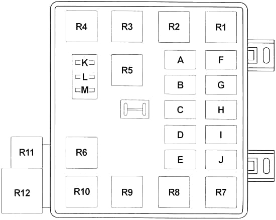
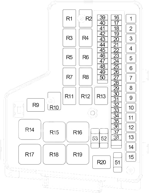
Fuse Box
| No. |
A |
Protected Component |
| 1 | 40 | ’02-’04: Trailer Tow Connector (’02-’03), Electric Brake Provision |
| 30 | ’05: Electric Brake Provision | |
| 2 | 30 | Gasoline: Auto Shut Down Relay |
| 3 | 30 | Ignition Switch (Run A38 (Integrated Power Module)) |
| 4 | 40 | Ignition Switch (Run C1 (Blower Motor)) |
| 5 | 40 | ’02-’04: Transmission Control Relay |
| 20 | ’05: Transmission Control Relay, Reverse Lockout Solenoid (SRT (Manual Transmission)) | |
| 6 | 40 | Controller Antilock Brake (ABS (AWAL/RWAL)) |
| 7 | 50 | Power Seat Switch – Driver, Power Seat Switch – Passenger, Passenger Lumbar Switch (’02-’04 – Standard Cab) |
| 8 | 30 | Wiper High/Low Relay, Wiper On/Off Relay |
| 9 | 40 | Ignition Switch (Run ACC F1 (Circuit Breaker (25A): Power Window)) |
| 10 | 40 | Ignition Switch (Run ACC A31) |
| 11 | 30 | Front Control Module |
| 12 | – | ’02: – |
| 30 | ’03-’05 (Gasoline): Condenser Fan Relay | |
| 40 | ’03-’05 (Diesel): Fuel Heater Relay | |
| 13 | 30 | Front Control Module |
| 14 | 30 | Starter Motor Relay |
| 15 | 50 | Park Lamp Relay |
| 16 | 10 | Air Conditioner Compressor Clutch Relay |
| 17 | 15 | ’02-’04: Glove Box Lamp and Switch (’02-’03), Driver Door Module (’02-’03 (except Base)), Compass/Mini Trip Computer (except Base), Dome Lamp (’02-’03), Overhead Map/Reading Lamp (’02-’03 (except Base)), Center High Mounted Stop Lamp (’02-’03), Cargo Lamp (’02-’03), Fuel Pump Relay (’03-’04), Sentry Key Immobilizer Module (’04) |
| 20 | ’05 (Gasoline): Fuel Pump Relay | |
| 18 | 15 | Cluster, Underhood Lamp, Data Link Connector, Radio |
| 19 | 10 | ’02-’03: Sentry Key Immobilizer Module, Powertrain Control Module |
| 20 | ’04-’05: Trailer Tow Connector | |
| 20 | 25 | Ignition Switch (Run-Start A21, Start A41, Off-Run-Start A51 (Cluster, Powertrain Control Module, Integrated Power Module, Push Button Starter Switch)) |
| 21 | 20 | Audio Amplifier |
| 22 | 20 | Cluster |
| 23 | – | ’02-’03: – |
| 15 | ’04-’05: Powertrain Control Module, Electronic Overhead Module, Sentry Key Immobilizer Module | |
| 24 | 15 | Stop Lamp Switch |
| 25 | 20 | Power Outlet – Console |
| 26 | 25 | ’02-’03: Transfer Case Selector Switch |
| 25 | ’04-’05: Rear Window Defogger Relay | |
| 27 | 15 | Heated Mirror Relay |
| 28 | 10 | Cluster, Compass/Mini Trip Computer (except Base), Automatic Day/Night Mirror (except Base), Door Lock Switch – Passenger (except Base) |
| 29 | 20 | Cigar Lighter, Rear Power Outlet (SRT) |
| 30 | – | ’02-’04: – |
| 30 | ’05 (Off Road): Clutch Interlock Switch, Powertrain Control Module | |
| 31 | – | – |
| 32 | 10 | Park/Turn Signal Lamp – Right Front, Tail/Stop Turn Signal Lamp – Right, License Lamp – Right, Center Bazel Lamp, Clearance Lamp, Fender Lamp |
| 33 | 20 | Trailer Tow Connector, Trailer Tow Connector Add On (Heavy Duty) |
| 34 | 10 | Park/Turn Signal Lamp – Left Front, Tail/Stop Turn Signal Lamp – Left, License Lamp – Left (+Right), Tailgate Bar Lamp, Fender Lamp |
| 35 | 10 | Controller Antilock Brake (ABS) |
| 36 | 10 | Heating and Air Conditioning Control, Radiator Fan Drive (Diesel (’04-’05)), Wastegate Solenoid (Diesel (’05)) |
| 37 | – | – |
| 38 | 15 | Transfer Range Sensor (Automatic Transmission), Transmission Solenoid/TRS Assembly, Backup Lamp Switch (Manual Transmission) |
| 39 | 25 | ’02: Condenser Fan Relay |
| – | ’03-’04: – | |
| 20 | ’05 (Diesel): Fuel Pump Relay | |
| 40 | 15 | Adjustable Pedal Relay |
| 41 | 15 | Fog Lamp Relay |
| 42 | 20 | Power Outlet – Console |
| 43 | 25 | Transfer Case Control Module, Subwoofer Amplifier (SRT), Final Drive Control Module (Off Road) |
| 44 | 20 | ’02: Fuel Pump Relay |
| – | ’03-’05 (Gasoline: – | |
| 45 | 20 | Horn Relay |
| 46 | 15 | Trailer Tow Left Turn Relay |
| 47 | 15 | Trailer Tow Right Turn Relay |
| 48 | 20 | Seat Heater Module, Window/Door Lock Switch – Driver (’05) |
| 49 | 20 | California: Oxygen Sensor Downstream Relay |
| 20 | ’05 (SRT): Oxygen Sensor Downstream Relay, Oxygen Sensor – Front Left/Right | |
| 50 | 10 | EVAP Purge Solenoid (’02-’03, ’05 SRT), Front Control Module (’02), Final Drive Control Module (’05), Stop Lamp Switch (’05 – 5.7L), Brake Lamp Switch (’04), Sentry Key Immobilizer Module (’04-’05), Engine Control Module (Diesel (’03-’05)), Powertrain Control Module (Gasoline (’04-’05)) |
| 51 | 20 | Underhood Lamp, Data Link Connector, Radio, Cluster |
| 52 | 20 | ’02-’04: Airbag Control Module |
| 15 | ’05: Occupant Restraint Controller Module | |
| 53 | 20 | ’02-’04: Airbag Control Module, Passenger Airbag On/Off Switch |
| 15 | ’05: Occupant Restraint Controller Module, Passenger Airbag On/Off Switch | |
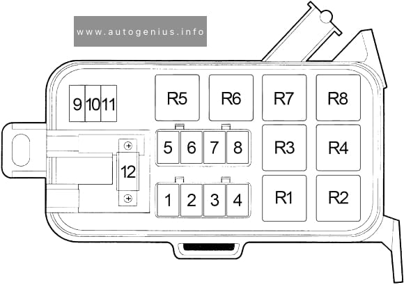
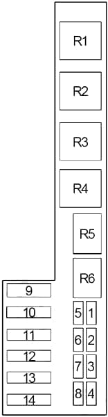
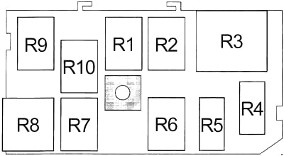
| Relay |
||
| R1 | ’02-’04: Spare | |
| ’05 (Diesel): Fuel Pump | ||
| R2 | ’02-’03: Condenser Fan | |
| ’04-’05: Spare | ||
| R3 | Fog Lamp | |
| R4 | Gasoline: Auto Shut Down | |
| R5 | Adjustable Pedal | |
| R6 | Gasoline: Fuel Pump | |
| R7 | Air Conditioner Compressor Clutch | |
| R8 | Transmission Control | |
| R9 | Spare | |
| R10 | ’02-’04 (California): Oxygen Sensor Downstream | |
| ’05 (SRT): Oxygen Sensor Downstream | ||
| R11 | Spare | |
| R12 | Wiper High/Low | |
| R13 | Wiper On/Off | |
| R14 | Starter Motor | |
| R15 | ’02-’03: Spare | |
| ’04-’05 (Gasoline): Condenser Fan | ||
| ’04-’05 (Diesel): Fuel Heater | ||
| ’05 (SRT): Blower Motor | ||
| R16 | Spare | |
| ’05: Rear Window Defogger | ||
| R17 | Park Lamp | |
| R18 | Spare | |
| R19 | Spare | |
| R20 | Heated Mirror | |
WARNING: Terminal and harness assignments for individual connectors will vary depending on vehicle equipment level, model, and market.