BMW X1 (E84) – (2010 – 2015) – fuse box diagram
Year of production: 2010, 2011, 2012, 2013, 2014, 2015
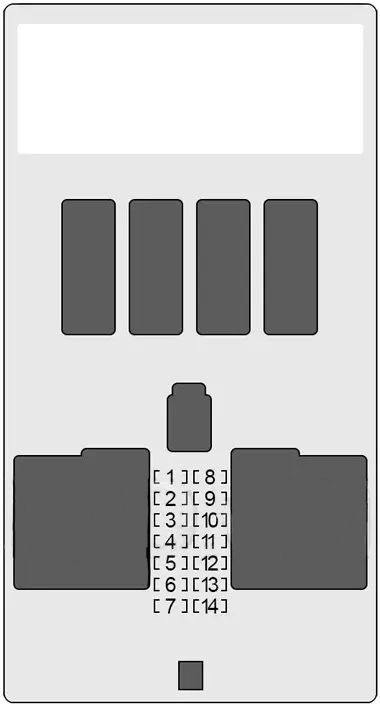
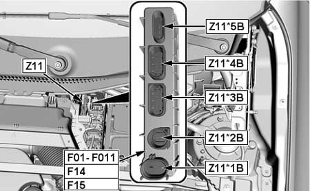
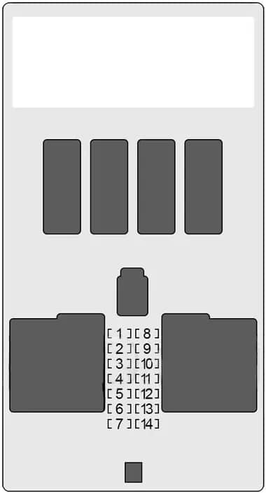
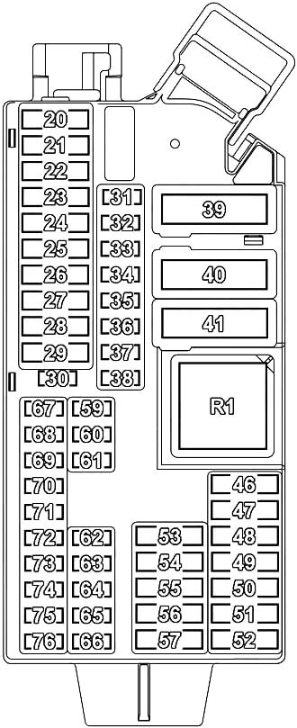
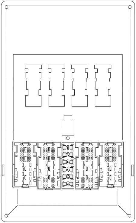
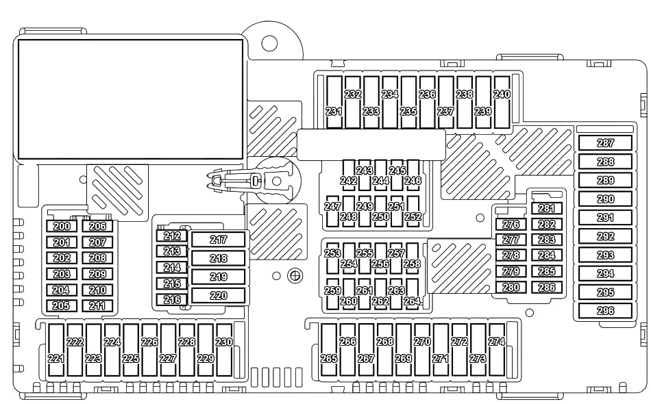
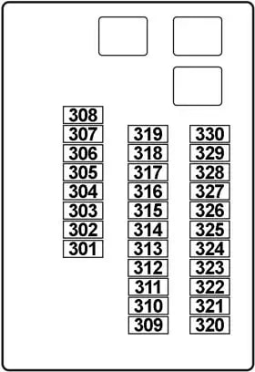
Passenger Compartment Fuse
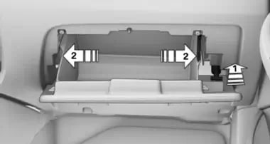
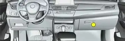
Access to fuse box:
- Open the glove compartment.
- Release the damper from the bottom holder by applying pressure toward the front, arrow 1.
- Unlock the glove compartment by pressing on both tabs, arrows 2, and fold down.
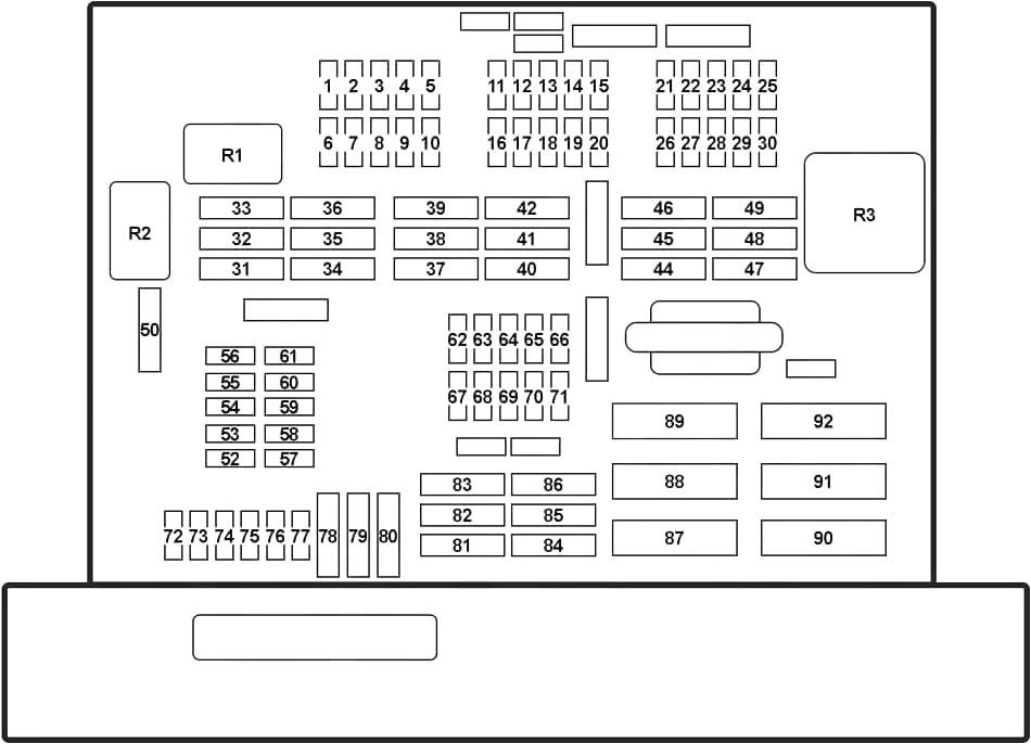
| No. |
A |
Protected Component |
| 1 | 20 | Rear Intermittent Wipe/Wash Control Unit |
| 2 | – | – |
| 3 | 20 | Electrochromic Interior Rear View Mirror |
| 4 | 10 | N20, N46, N52, N55: DME Control Unit (16i, 18i, 20i, 28i, 35i) |
| 5 | 10 | Steering Column Switch Center |
| 6 | 5 | AUC Sensor, DC/DC Converter |
| 7 | 5 | Park Distance Control (PDC), Roof Function Control Centre |
| 8 | 20 | Front Cigar Lighter, Rear Centre Console Charging Socket 1 & 2, Luggage Compartment Socket Outlet |
| 9 | 5 | Driver’s Switch Cluster, Telephone Transceiver, Telephone Retrofit Packages Connector |
| 10 | 5 | Driver’s Seat Heating Module, Passenger’s Seat Heating Module |
| 11 | 20 | N20, N55: DME Control Unit |
| 20 | N46 TU 2: Fuel Injectors | |
| 20 | N52: Oil Condition Sensor, DISA Actuator 1 & 2, Fuel Tank Vent Valve, Crankshaft Sensor, Air Mass Flow Sensor | |
| 12 | – | – |
| 13 | 10 | TCU, ULF, ULF-SBX, ULF-SBX-H, Combox, Eject Box, USB Hub |
| 14 | 15 | Car Information Computer (CIC), Radio (without CIC) |
| 15 | 20 | Audio Amplifier |
| 16 | 10 | N20, N55: DME Control Unit |
| 10 | N52: Radiator Shutter Drive Unit, E-Box Fan | |
| 10 | N46 TU 2: Crankshaft Sensor, Fuel Tank Vent Valve, Hot-Film Air Mass Meter, E-Box Fan | |
| 17 | 10 | N20, N46, N52, N55: Diagnostic Module for Fuel Tank Leakage, Exhaust Flap |
| 18 | 10 | Video Module, Digital Tuner |
| 19 | 5 | CD Changer |
| 20 | 10 | Driver’s/Passengers’s Lumbar Support Switch, Switch for Driver’s/Passenger’s Seat Backrest width Adjustment, Valve Block for Driver’s/Passenger’s Seat Backrest width Adjustment, Front Left/Right Lumbar Support Valve Block |
| 21 | – | – |
| 22 | 15 | Transmission Control, Transmission Control DKG |
| 23 | – | – |
| 24 | – | – |
| 25 | 20 | Panorama Glass Roof |
| 26 | 5 | Transfer Box Control Unit, Dynamic Stability Control (DSC) |
| 27 | 5 | Tyre Pressure Control (RDC) |
| 28 | 5 | Electric Fan Cut-Out Relay, DC/DC Converter |
| 29 | 5 | Korea: Tank Vent Shutoff Valve |
| 30 | – | – |
| 31 | 30 | Trailer Module |
| 32 | 30 | Trailer Module |
| 33 | 40 | except N20: Electric Coolant Pump |
| 40 | N47: Fuel Heater | |
| 34 | – | – |
| 35 | – | – |
| 36 | 40 | Car Access System |
| 37 | 10 | N20: DME Control Unit |
| 30 | N46 TU 2: Oxygen Sensor before Catalytic Converter, Oxygen Sensor 2 before Catalytic Converter, Oxygen Sensor after Catalytic Converter, Oxygen Sensor 2 after Catalytic Converter | |
| 30 | N52: Electric Coolant Pump, Characteristic Map Thermostat, Intake Camshaft Sensor, Exhaust Camshaft Sensor, Intake Vanos Solenoid Valve, Exhaust Vanos Solenoid Valve, Oil Pressure Control Valve | |
| 38 | 15 | N20: DME Control Unit |
| 30 | N46 TU 2: Ignition Coils | |
| 30 | N52: Oxygen Sensor before Catalytic Converter, Oxygen Sensor 2 before Catalytic Converter, Oxygen Sensor after Catalytic Converter, Oxygen Sensor 2 after Catalytic Converter, Crankshaft Breather Heating 1 | |
| 39 | 30 | N46 TU 2: DME Control Unit, Characteristic Map Thermostat, Intake Camshaft Sensor, Exhaust Camshaft Sensor, Intake Vanos Solenoid Valve, Exhaust Vanos Solenoid Valve, Oil Level Sensor, Crankcase Breather Heating |
| 30 | N52: Fuel Injectors, Ignition Coils, Interference Suppression Capacitor for Ignition Coils | |
| 40 | 30 | Transfer Box Control Unit |
| 41 | 30 | Driver’s Window Motor, Footwell Module |
| 42 | 40 | Audio Amplifier (HiFi System Professional, BMW Individual High-End Audio System, Harman Kardon Surround Sound System) |
| 43 | – | – |
| 44 | – | – |
| 45 | 30 | Passenger’s Seat Adjustment Switch |
| 46 | 30 | Driver’s Seat Module |
| 47 | 30 | Right Lockout Circuit for Rear Window Defogger |
| 48 | 30 | Headlight Washer Pump |
| 49 | 30 | Passenger’s Seat Module |
| 40 | Active Steering | |
| 50 | 30 | Wiper Motor |
| 51 | – | – |
| 52 | – | – |
| 53 | – | – |
| 54 | 7.5 | Siren and Tilt Alarm Sensor |
| 55 | 5 | Car Access System |
| 56 | 20 | – |
| 57 | 15 | Horn |
| 58 | 5 | All-Round Vision Camera |
| 59 | 5 | Combox, Telematics Control Unit (TCU) (USA), Eject Box (USA) |
| 60 | – | – |
| 61 | 5 | Comfort Access Control Unit, Driver’s Side Outer Door Handle Electronic Module, Passenger’s Side Outer Door Handle Electronic Module |
| 62 | 7.5 | Roof Function Control Centre |
| 63 | 5 | Gear Indicator Lighting, Aerial Diversity (Noise Suppressor Filter) |
| 64 | – | – |
| 65 | 10 | Longitudinal Dynamics Management, Gear Indicator Lighting (Automatic Transmission), Gear Selector Switch (Double Clutch Transmission) |
| 66 | 7.5 | Driver’s Switch Cluster, Passenger’s Side Outside Mirror |
| 67 | 20 | Electric Fuel Pump |
| 68 | 20 | Driver’s Seat Heating Module |
| 69 | – | – |
| 70 | 20 | Fuel Pump Control (EKPS) |
| 71 | 20 | Trailer Socket |
| 72 | 15 | Driver’s Door System Lock |
| 73 | 15 | Passenger’s Door System Lock |
| 74 | 5 | Instrument Cluster Control Unit |
| 75 | 5 | Steering Column Switch Cluster |
| 76 | 10 | Central Information Display |
| 77 | 10 | Luggage Compartment Light, Glove Compartment Light, Heating/Air Conditioning System |
| 78 | 30 | Rear Driver’s Side Power Window Motor |
| 79 | 30 | – |
| 80 | 30 | Rear Passenger’s Side Power Window Motor |
| 81 | 30 | Driver’s Window Motor |
| 82 | 30 | Dynamic Stability Control (DSC – without Automatic Engine Start-Stop), DC/DC Converter (with Automatic Engine Start-Stop) |
| 83 | – | – |
| 84 | 40 | Footwell Module |
| 85 | 30 | DC/DC Converter |
| 86 | 40 | Footwell Module |
| 87 | – | – |
| 88 | 40 | Blower Output Stage |
| 89 | 40 | Secondary Air Pump Relay |
| 90 | 40 | Dynamic Stability Control (DSC) |
| 91 | 15 | Passenger’s Door System Lock |
| 92 | 50 | Fan 400W: Electric Fan Cut-Out Relay |
| 60 | Fan 600W: Electric Fan Cut-Out Relay | |
| Relay | ||
| R1 | Rear Window Wiper | |
| R2 | Wiper (Relay No.1) | |
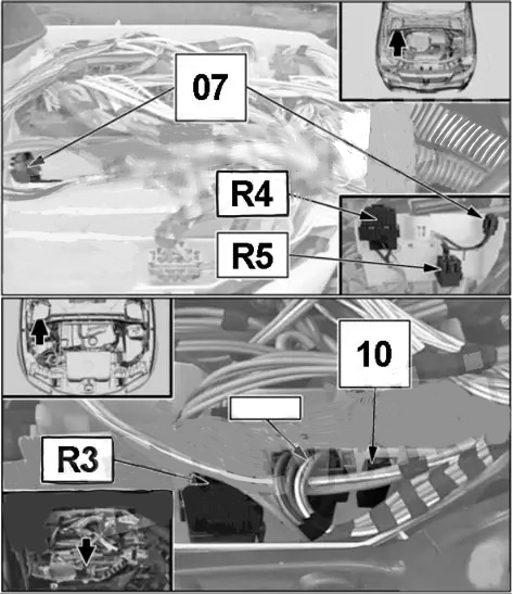
| R3 | Terminal 30G | |
| R4 | Wiper (Relay No.2) | |
| R5 | Petrol: Digital Motor Electronics (DME) Main | |
| R6 | Headlight Cleaning System | |
| R7 | Fuel Pump | |
Secondary Air Pump Relay
- Petrol Engines:
sDrive16i – 1.6 Turbo (N20B16)
sDrive18i – 2.0 L (N46B20)
sDrive20i, sDrive28i & xDrive28i – 2.0 Turbo (N20B20)
xDrive25i & xDrive28i (’11-’15) – 3.0 L (N52B30)
xDrive35i – 3.0 Turbo (N55B30) - Diesel Engines:
sDrive16d, sDrive18d, sDrive20d, sDrive20d EfficientDynamics – 2.0 Turbo (N47D20)
xDrive18d, xDrive20d – 2.0 Turbo (N47D20)
xDrive23d, xDrive25d – 2.0 Twin-Turbo (N47D20)
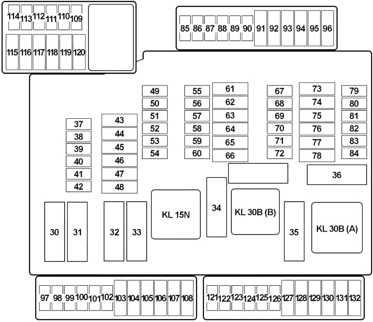
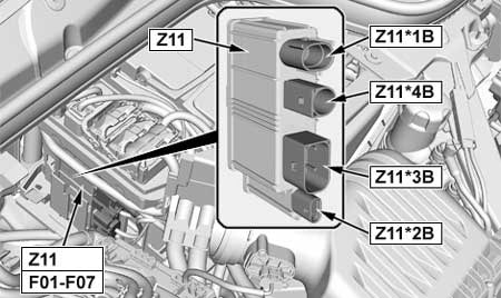
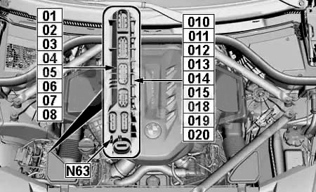
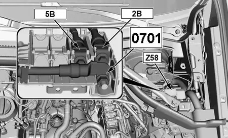
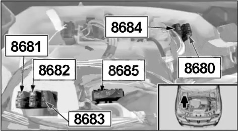
Engine Compartment Fuses (N20, N55)
| No. |
A |
Protected Component |
| 8680 | – | – |
| 8681 | 15 | N20: Digital Motor Electronics (DME) Control Unit |
| 20 | N55: Digital Motor Electronics (DME) Control Unit | |
| 8682 | 20 | N20: Digital Motor Electronics (DME) Control Unit |
| 15 | N55: Digital Motor Electronics (DME) Control Unit | |
| 8683 | 40 | N20: Digital Motor Electronics (DME) Control Unit |
| 40 | N55: Valvetronic Relay | |
| 8684 | – | – |
| 8685 | 30 | Coolant Pump 200W (N20): Electric Coolant Pump |
| 50 | Coolant Pump 400W (N20): Electric Coolant Pump | |
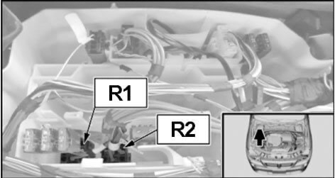
| Relay | ||
| R1 | Variable Valve Gear | |
| R2 | Ignition and Fuel Injection | |
Variable Valve Gear/Ignition and Fuel Injection
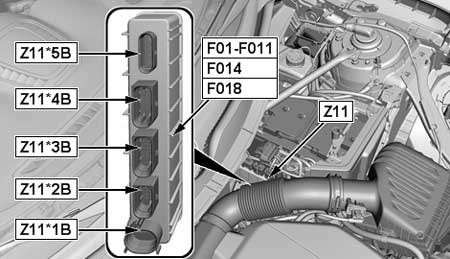
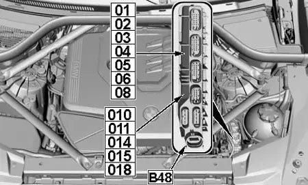
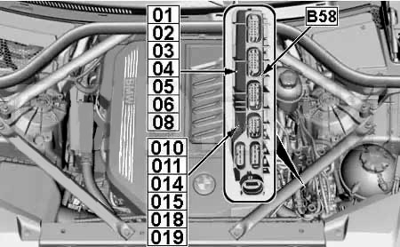
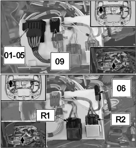
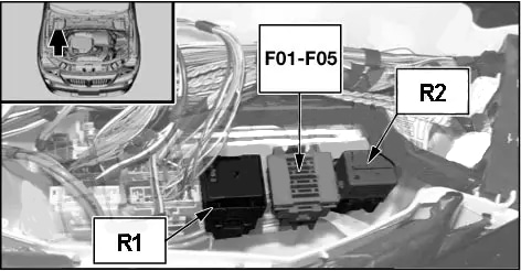
Engine Compartment Fuses (N52)
| No. |
A |
Protected Component |
| 01 | 30 | Ignition Coils, Interference Suppression Capacitor for Ignition Coils |
| 02 | 30 | Electric Coolant Pump, Characteristic Map Thermostat, Intake Camshaft Sensor, Exhaust Camshaft Sensor, Intake Vanos Solenoid Valve, Exhaust Vanos Solenoid Valve |
| 03 | 20 | Digital Motor Electronics (DME) Control Unit, Oil Condition Sensor, Disa Actuator No.1 & 2, Fuel Tank Vent Valve, Crankshaft Sensor, Air Mass Flow Sensor |
| 04 | 10 | Oxygen Sensor No.1 & 2 before Catalytic Converter, Oxygen Sensor No.1 & 2 after Catalytic Converter, Crankshaft Breather Heating |
| 05 | 30 | Fuel Injectors Relay |
| 06 | 10 | Secondary Air Pump Relay, Exxhaust Flap, E-Box Fan, Diagnostic Module for Fuel Tank Leakage (USA), Secondary Air – Hot-Film Air-Mass Meter |
| 09 | 30 | Electric Coolant Pump |
| Relay | ||
| R1 | Digital Motor Electronics (DME) | |
| R2 | Fuel Injectors | |
Secondary Air Pump Relay
| No. |
A |
Protected Component |
| 07 | 40 | VVT Relay |
| 10 | 5 | Engine Breather Heating |
| Relay | ||
| R3 | Crankcase Ventilation Heater | |
| R4 | Electric Fan Cutoff | |
| R5 | VVT | |
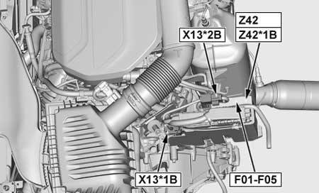
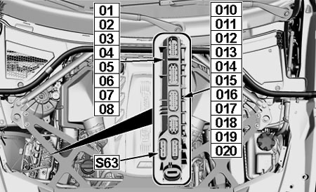
Engine Compartment Fuses (Diesel N47)
| No. |
A |
Protected Component |
| 01 | 20 | Boost Pressure Adjuster 1, Throttle Valve, Camshaft Sensor, Rail Pressure Control Valve, Volume Control Valve |
| 20 | 25d: Rail Pressure Control Valve, Volume Control Valve, Camshaft Sensor, Turbine Control Valve, Changeover Valve Low Pressure Compressor Bypass Flap, Wastegate Valve | |
| 02 | 20 | Exhaust Recirculation Actuator, Hot-Film Air Mass Meter, Exhaust Recirculation Cooler Bypass, Oxygen Sensor before Catalytic Converter, Preheating Control Unit, Oil Condition Sensor |
| 20 | 25d: Oil Level Sensor, Exhaust Recirculation Cooler Bypass Solenoid Valve, Preheating Control Unit, Compressor Bypass Valve, Engine Mount Electrical Changeover Valve, Air Mass Flow Sensor, Oxygen Sensor before Catalytic Converter | |
| 03 | 30 | Digital Diesel Electronics (DDE) Control Unit |
| 04 | 10 | E-Box Fan (except25d), Crankcase Breather Heating |
| 05 | – | – |
| Relay | ||
| R1 | Electric Fan Cutoff | |
| R2 | Digital Diesel Electronics (DDE) Control Unit (Main Relay) | |
| No. |
A |
Protected Component |
| 26 | 5 | with Start-Stop: Dynamic Stability Control (DSC) |
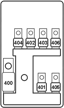
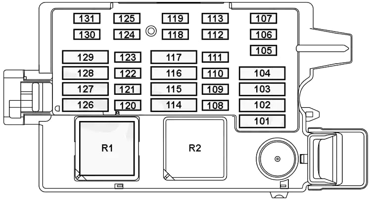
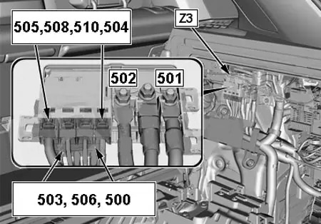
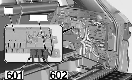
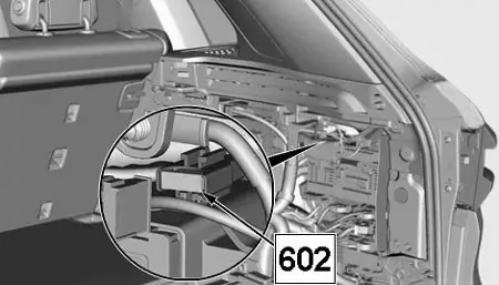
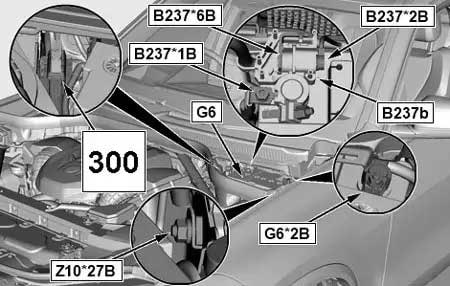
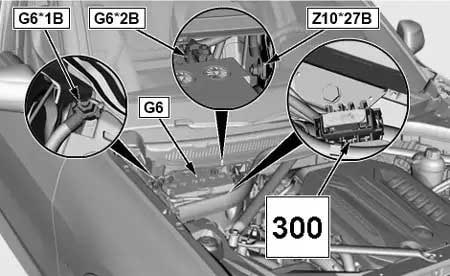
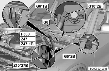
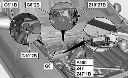
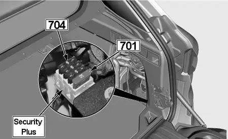
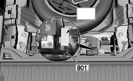
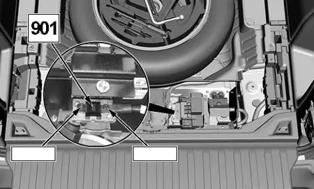
Main Fuse Box (Battery)
| No. |
A |
Protected Component |
| 101 | 250 | Passenger Compartment Fuse Box |
| 102 | 100 | Jump Start Terminal Point (DDE Main Relay) |
| 103 | 100 | Electromechanical Power Steering |
| 104 | 100 | Electric Auxiliary Heater (Diesel) |
| 105 | – | Battery Sensor |
WARNING: Terminal and harness assignments for individual connectors will vary depending on vehicle equipment level, model, and market.