BMW X7 (G07) – (2018 – 2022) – fuse box diagram
Year of production: 2018, 2019, 2020, 2021, 2022
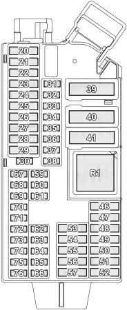
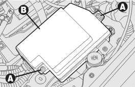
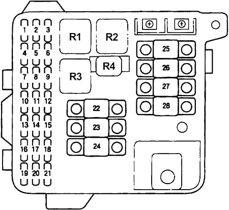
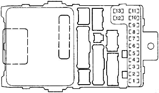
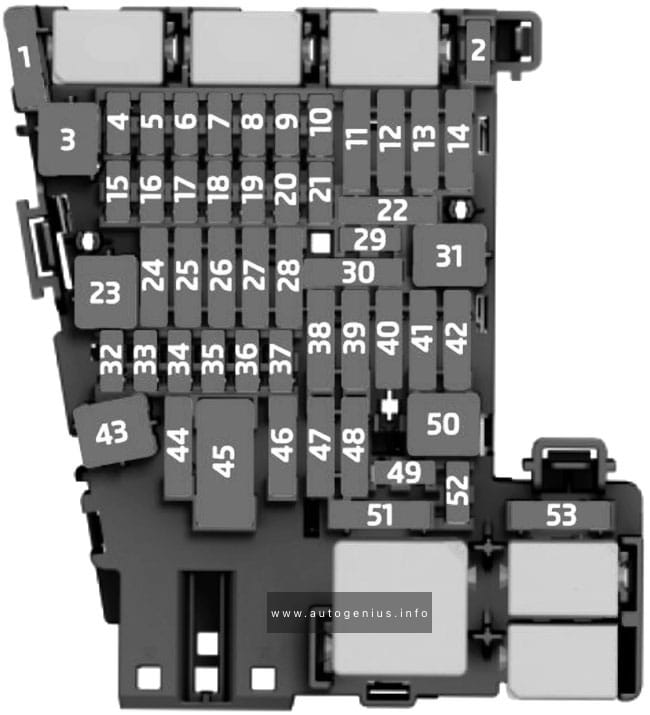
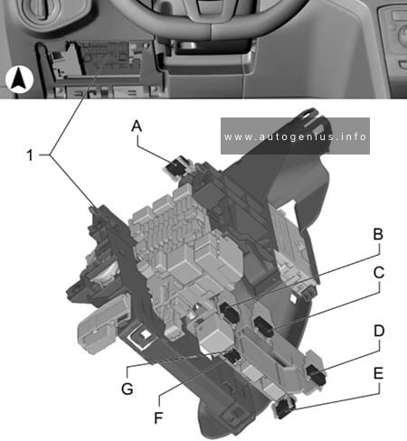
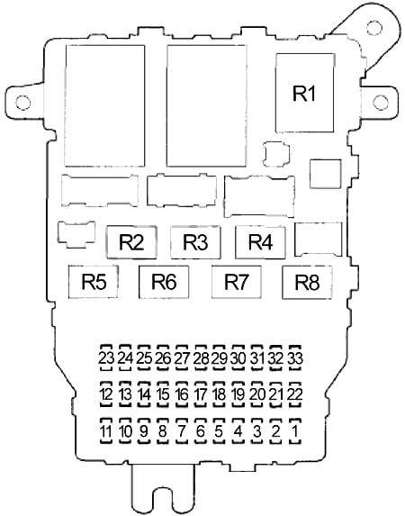
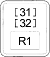
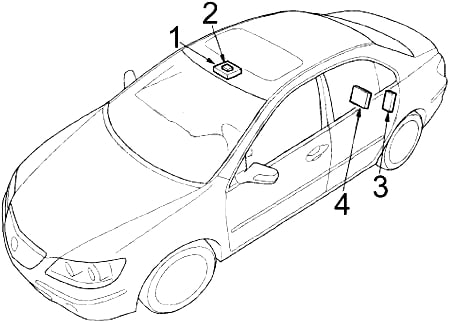
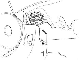
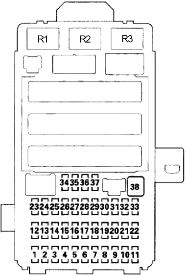
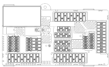
Passenger Compartment Fuse Box No.1 (Passenger’s Side)

| No. |
A |
Protected Component |
| 20 | 30 | Driver’s Door Power Window Drive with Control Electronics |
| 21 | 30 | Front Passenger Door Power Window Drive with Control Electronics |
| 22 | 30 | Driver’s Side Rear Power Window Drive with Control Electronics |
| 23 | 30 | Passenger’s Side Rear Power Window Drive with Control Electronics |
| 24 | 30 | Left Reversible Electromotive Automatic Reel (Seat Belt) |
| 25 | 20 | Roof Function Centre |
| 26 | 20 | Body Domain Controller |
| 27 | – | – |
| 28 | 40 | Dynamic Stability Control (DSC) |
| 29 | 15 | Body Domain Controller |
| 30 | – | – |
| 31 | – | – |
| 32 | 5 | Centre Console Control Panel |
| 33 | 5 | Driver Electronic Outer Door Handle Module |
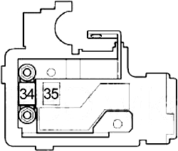
| 34 | 5 | Instrument Cluster Control Unit |
| 35 | – | – |
| 36 | 5 | Roof Function Centre (Map Reading Light, Interior Light, Ambient Light) |
| 37 | 10 | Output Stage for Rear Compartment Fan Motor (4-zone Air Conditioning) |
| 38 | – | – |
| 39 | 60 | Body Domain Controller |
| 40 | 40 | Blower Motor with Output Stage |
| 41 | – | – |
| 46 | 20 | Rear Cigarette Lighter, Front Cigarette Lighter (without Thermoelectric Cup Holder), Thermoelectric Cup Holder |
| 47 | 30 | Wiper Module |
| 48 | – | – |
| 49 | 20 | Electric Steering Column Adjustment |
| 50 | 15 | Thermoelectric Cup Holder |
| 51 | 30 | B58, N63: Electronic Transmission Control, Transfer Box |
| 52 | – | – |
| 53 | 30 | Driver’s Seat Module (with Seat Module), Driver’s Side Seat Adjustment Switch Block (without Seat Module) |
| 54 | 20 | Independent Auxiliary Heater (SHZH) |
| 55 | 30 | Front Passenger Seat Module (with Seat Module), Front Passenger Side Seat Adjustment Switch Block (without Seat Module) |
| 56 | 10 | Front Passenger’s Side Control Electronics for Armrest Heating |
| 57 | 10 | Driver’s Side Control Electronics for Armrest Heating |
| 59 | 5 | USB Connection No.2, Electrochromic Interior Rear View Mirror |
| 60 | 5 | Centre Rear Door Trim Panel Lighting (Driver’s Side), Rear Door Pocket Lighting (Driver’s Side), Rear Inner Door Handle Lighting (Driver’s Side), Rear Driver’s Side Door Trim Panel Lighting (Top), Rear Left Speaker Lighting, Auxiliary Water Pump (Diesel) |
| 61 | 5 | Glove Compartment Light Switch, Driver Camera System, 48 Volt Power Control Unit (PCU48), 48 Volt Battery |
| 62 | 5 | Panorama Roof Roller Blind Drive No.2 |
| 63 | 5 | Auxiliary Battery, Instrument Panel Speaker Lighting, Air Freshener, CD Drive, Ioniser, Starter Motor Generator 48 Volt (B57, B58) |
| 64 | 10 | Driver’s Seat Backrest width Adjustment Valve Block, Driver Lumbar Support Valve Block, Seat Adjustment Switch Block (Driver’s Side), Rear Footwell Light (Driver’s Side), Driver’s Seat Backrest Rear Panel Lighting, USB Charging Socket, Front Left Seat Inflator Module |
| 65 | 10 | Front Passenger Backrest width Adjustment Valve Block, Front Passenger Lumbar Support Valve Block, Seat Adjustment Switch Block (Front Passenger Side), Rear Footwell Light (Front Passenger Side), Front Passenger Seat Backrest Rear Panel Lighting, USB Charging Socket No.2, Front Right Seat Inflator Module |
| 66 | 5 | Top Centre Dashboard Lighting, Top Front Passenger’s Side Instrument Panel Lighting, Bottom Centre Instrument Panel Lighting, Bottom Driver’s/Passenger’s Side Instrument Panel Lighting, Contour Line Lighting in Third Row of Seats on Driver’s/Passenger’s Side Rear, Front Left/Right Footwell Light |
| 67 | 5 | Driver’s Door Switch Block, Seat Switch Cluster on Driver’s Door, Driver’s Door Inner Door Handle Lighting, Driver’s Door Trim Panel Lighting (Centre), Driver’s Door Pocket Lighting, Driver’s Door Trim Panel Lighting (Top), Front Left Mid-Range Speaker Lighting, Front Left Tweeter Lighting |
| 68 | 5 | Front Passenger Exterior Mirror, Passenger’s Door Switch Block, Passenger’s Door Inner Door Handle Lighting, Front Passenger Door Trim Panel Lighting (Centre), Passenger’s Door Pocket Lighting, Front Passenger Door Trim Panel Lighting (Top), Front Right Mid-Range Speaker Lighting, Front Right Tweeter Lighting |
| 69 | 5 | Radiator Blind Drive (Top, Bottom) |
| 70 | 5 | Rear Power Distribution Box, Electric Fan Cut-Out Relay, Electric Fan |
| 71 | 5 | All-Round Vision Camera (with Omnidirectional Camera), Reversing Camera |
| 72 | 7.5 | USB Charging Socket No.3 (Rear Console) |
| 73 | 5 | Instrument Cluster Control Unit |
| 74 | 10 | Steering Column Switch Cluster |
| 75 | 10 | Crash Safety Module |
| 76 | 15 | Auxiliary Coolant Pump (Rear Air Conditioner) |
| Relay | ||
| R1 | Terminal 30B | |
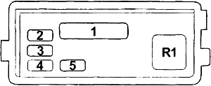
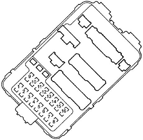
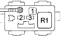
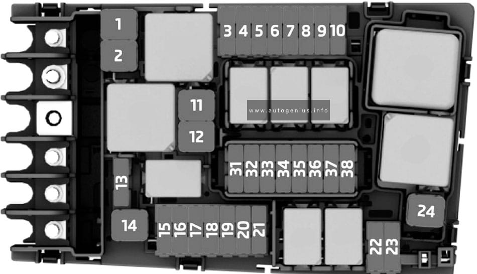
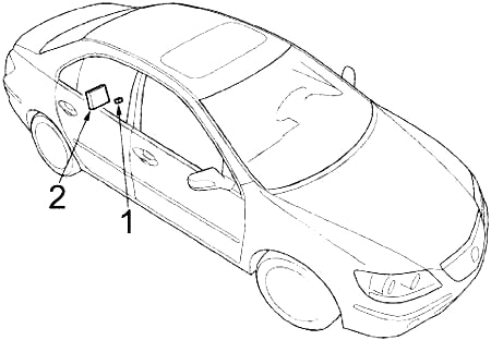
Passenger Compartment Fuse Box No.2 (Passenger’s Side (Body Domain Controller))
| No. |
A |
Protected Component |
| 1 | 5 | Steering Column Switch Cluster, Front Centre Ventilation Grille, Audio Control Panel, Light Operating Unit, Headunit |
| 2 | 7.5 | Diagnosis Socket, Electronic Ride-Height Control, Vertical Dynamics Platform |
| 3 | 7.5 | Heating/Air Conditioning System, Tailgate Function Module, Rain/Light/Solar/Condensation Sensor |
| 4 | 5 | Passenger Electronic Outer Door Handle Module, Rear Driver’s Side Outer Door Handle Electronic Module, Rear Passenger’s Side Outer Door Handle Electronic Module, Power Control Unit, Telematic Communication Box |
| 5 | 20 | Locking Relay, Unlocking Relay (Doors, Fuel Filler Flap) |
| 6 | 20 | Driver’s Door Locking Relay, Deadlocking Relay (Driver’s Door Lock, Front Passenger Door Lock, Rear Driver’s Side Doorl Lock, Rear Passenger’s Side Door Lock, Fuel Filler Flap Central Locking Locking Drive) |
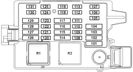
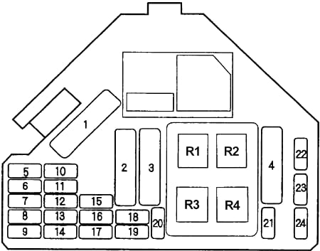
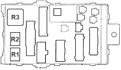
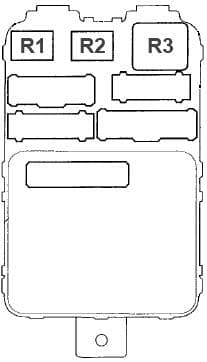
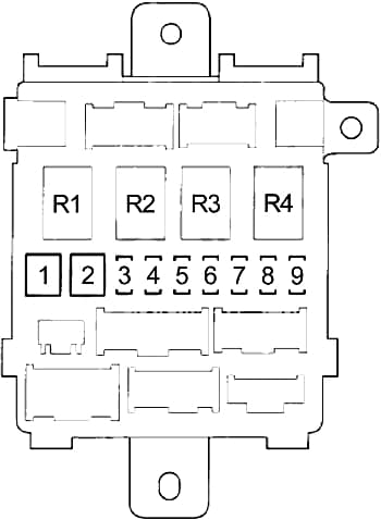
Passenger Compartment Fuse Box No.3 (Driver’s Side)

| No. |
A |
Protected Component |
| 101 | – | – |
| 102 | – | – |
| 103 | – | – |
| 104 | – | – |
| 105 | 7.5 | – |
| 106 | – | – |
| 107 | 10 | – |
| 108 | – | – |
| 109 | – | – |
| 110 | 5 | – |
| 111 | 5 | Rear Power Distribution Box |
| 112 | – | – |
| 113 | – | – |
| 114 | – | – |
| 115 | – | – |
| 116 | – | – |
| 117 | 30 | – |
| 118 | – | – |
| 119 | – | – |
| 120 | – | – |
| 121 | – | – |
| 122 | – | – |
| 123 | – | – |
| 124 | – | – |
| 125 | – | – |
| 126 | – | – |
| 127 | – | – |
| 128 | – | – |
| 129 | – | – |
| 130 | – | – |
| 131 | – | – |
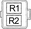
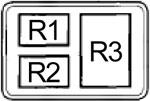
| Relay | ||
| R1 | ||
| R2 | ||
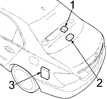
Luggage Compartment Fuse Box
| No. |
A |
Protected Component |
| 200 | – | – |
| 201 | – | – |
| 202 | – | – |
| 203 | 7.5 | Electrical Exhaust Flap (B58, N63), Electrical Exhaust Flap No.2 (N63) |
| 204 | 5 | Rear Axle King Pin Inclination Control, AUC Sensor, Regulated Rear Axle Differential Lock |
| 205 | – | – |
| 206 | – | – |
| 207 | 5 | Front Left/Right Side Radar Sensor Near Range, Rear Left/Right Radar Sensor Near, Optional Extra System |
| 208 | 5 | Electromechanical Power Steering |
| 209 | 5 | Long-Distance Range Front Radar Sensor (Active Cruise Control (High Version)), Front Radar Sensor (Basic Cruise Control (High Version)), Front Electric Active Roll Stabilisation, Rear Electric Active Roll Stabilisation |
| 210 | 5 | Electric Fuel Pump Control Electronics |
| 211 | 5 | Electronic Night Vision Module (BMW Night Vision) |
| 212 | 15 | Headunit |
| 213 | 15 | Trailer Socket |
| 214 | 5 | Subwoofer |
| 215 | 10 | Rear Seat Entertainment |
| 216 | 5 | Wireless Charging Oddments Tray Aerial Amplifier |
| 217 | 40 | Subwoofer |
| 218 | 20 | 12V Connection No.2 (Luggage Compartment) |
| 219 | – | – |
| 220 | 30 | Receiver Audio Module |
| 221 | – | – |
| 222 | – | – |
| 223 | – | – |
| 224 | 20 | Vertical Dynamics Platform (Executive Drive Pro) |
| 225 | – | – |
| 226 | 40 | Tailgate Function Module |
| 227 | 30 | Selective Catalytic Reduction (SCR) Control Unit |
| 228 | – | – |
| 229 | – | – |
| 230 | 30 | Right Reversible Electromotive Automatic Reel (Seat Belt) |
| 231 | 30 | Rear Window Defogger |
| 232 | 30 | Rear Window Defogger |
| 233 | 20 | Blower Output Stage (Rear Air Conditioning System) |
| 234 | – | – |
| 235 | – | – |
| 236 | – | – |
| 237 | – | – |
| 238 | – | – |
| 239 | – | – |
| 240 | 20 | Trailer Module |
| 242 | – | – |
| 243 | – | – |
| 244 | 5 | Remote Control Receiver, Natural Vacuum Leak Detection, Siren with Tilt Alarm Sensor, High-Voltage Battery Unit (Hybrid), Safety Battery Terminal Gas Generator (with Dual Storage System, with 48V System) |
| 245 | – | – |
| 246 | – | – |
| 247 | 15 | Rear Compartment Air Conditioning System |
| 248 | – | – |
| 249 | 10 | Passenger’s Door Automatic Soft-Close Drive |
| 250 | 5 | Interior Lights, Vanity Mirror Lights, Glass Sunroof Lighting |
| 251 | 10 | Driver’s Door Automatic Soft-Close Drive |
| 252 | 5 | Auxiliary Battery |
| 253 | 7.5 | Parking Assistant, Automatic Rear Air Conditioning Operating Facility, Camera-Based Drive Assistance System, Rear Right Seat Heating Switch |
| 254 | 5 | Luggage Compartment Lights, Tailgate Button for Lower Tailgate, Rear Lid Button on Inside of Rear Lid |
| 255 | 5 | Switch Block of Luggage Compartment, Operating Unit for the Rear Airr Conditioner, Seat Heating Operating Unit in Third Row of Seats (without Rear Air Conditioner) |
| 256 | 10 | Rear Passenger’s Side Automatic Soft Close Drive, Switch Block of Passenger’s Side Rear Roller Sunblind (with Electric Roller Sunblinds) |
| 257 | 5 | Rear Right Speaker Lighting, Rear Passenger’s Side Door Pocket Lighting, Rear Passenger’s Side Inner Door Handle Lighting, Centre Rear Passenger’s Side Door Trim Panel Lighting, Top Rear Passenger Door Trim Panel Lighting, Left/Right Reversible Electromotive Automatic Reel |
| 258 | 10 | Rear Driver’s Side Automatic Soft-Close Drive, Switch Block of Driver’s Side Rear Roller Sunblind (with Electric Roller Sunblinds) |
| 259 | 15 | Selective Catalytic Reduction (SCR) Control Unit |
| 260 | 10 | Soft-Close Automatic for Left Lower Tailgate |
| 261 | 5 | USB Charging Socket No.: 4 & 5 (Third Row of Seats) |
| 262 | 5 | Controller, Self-Leveling Suspension Button, Wireless Charging Oddments Tray, Lighting for Centre Console, Front Centre Armrest Light |
| 263 | 10 | Soft-Close Automatic for Right Lower Tailgate |
| 264 | 10 | Boot Lid/Tailgate Lock |
| 265 | 30 | Regulated Rear Axle Differential Lock |
| 266 | 20 | Trailer Module |
| 267 | 30 | Trailer Module |
| 268 | – | – |
| 269 | 30 | Rear Driver’s Side Seat Module |
| 270 | 30 | Electric Fuel Pump Control Electronics |
| 271 | 30 | Rear Passenger’s Side Seat Module |
| 272 | – | – |
| 273 | – | – |
| 274 | 30 | Seat Heating Electronics in Third Row of Seats |
| 276 | – | – |
| 277 | – | – |
| 278 | – | – |
| 279 | 5 | Contactfree Tailgate Opening Evaluation Electronics |
| 280 | – | – |
| 281 | – | – |
| 282 | – | – |
| 283 | – | – |
| 284 | – | – |
| 285 | – | – |
| 286 | – | – |
| 287 | – | – |
| 288 | – | – |
| 289 | 20 | Trailer Module |
| 290 | – | – |
| 291 | – | – |
| 292 | – | – |
| 293 | – | – |
| 294 | – | – |
| 295 | – | – |
| 296 | – | – |
| Relay | ||
| R1 | Terminal 30B | |
- Petrol Engines:
B58 – 3.0L (xDrive40i)
N63 – 4.4L V8 (xDrive50i and M50i) - Diesel Engines:
B57 – 3.0L (xDrive30d, xDrive40d & M50d)
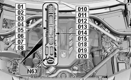
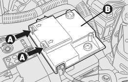
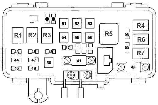
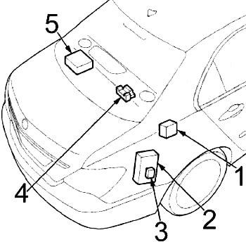
Integrated Supply Module (N63 – xDrive50i, M50i)

The integrated supply module contains fuses and relays. If one of the fuses or one of the relays is faulty, the complete integrated supply module must be renewed.
| No. | A | Protected Component |
| 01 | 7.5 | Oil Level Sensor, Oil Pressure Control Valve, Complete Heater Circuit Shutoff Valve |
| 02 | 5 | Turbocharger Coolant Pump |
| 03 | 10 | Coolant Pump Shift Element |
| 04 | 15 | M50i: Blow Off Valve 1 & 2 |
| 05 | 20 | Characteristic Map Thermostat, Oxygen Sensor before Catalytic Converter, Oxygen Sensor after Catalytic Converter |
| 06 | 15 | Coolant Pump in Low Temperature Coolant Circuit |
| 07 | 15 | Oxygen Sensor No.2 before Catalytic Converter, Oxygen Sensor No.2 after Catalytic Converter |
| 08 | 15 | Digital Motor Electronics (DME) |
| 010 | 30 | Digital Motor Electronics (DME) |
| 011 | 20 | Digital Motor Electronics (DME) |
| 012 | 30 | Digital Motor Electronics (DME) No.2 |
| 013 | 20 | Digital Motor Electronics (DME) No.2 |
| 014 | 40 | Digital Motor Electronics (DME) |
| 015 | 40 | Digital Motor Electronics (DME) No.2 |
| 018 | 10 | Intake/Exhaus VANOS Solenoid Actuator, Tank Vent Valve |
| 019 | 10 | Intake/Exhaus VANOS Solenoid Actuator No.2, Tank Vent Valve No.2 |
| 020 | 15 | Digital Motor Electronics (DME) No.2 |
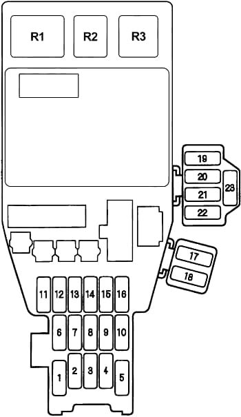
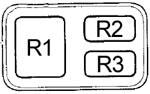
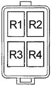
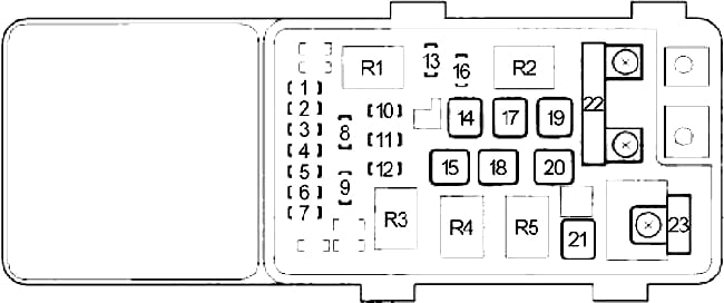
Integrated Supply Module (B58 – xDrive40i)
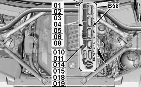
The integrated supply module contains fuses and relays. If one of the fuses or one of the relays is faulty, the complete integrated supply module must be renewed.
| No. | A | Protected Component |
| 01 | 7.5 | Oil Level Sensor, Oil Pressure Control Valve, Heat Management Module |
| 02 | 5 | Turbocharger Coolant Pump |
| 03 | – | – |
| 04 | 15 | Engine Ventilation Heating |
| 05 | 20 | Oxygen Sensor before Catalytic Converter, Oxygen Sensor after Catalytic Converter, Blow-Off Valve (with Additional Scope, RDE) |
| 06 | 15 | Coolant Pump in Low-Temperature Coolant Circuit |
| 07 | – | – |
| 08 | 15 | Digital Motor Electronics (DME) |
| 09 | 20 | Coolant Pump in Low-Temperature Coolant Circuit |
| 010 | 30 | Digital Motor Electronics (DME) |
| 011 | 20 | Digital Motor Electronics (DME) |
| 014 | 40 | Digital Motor Electronics (DME) |
| 015 | 40 | Transmission Oil Pump |
| 018 | 10 | Digital Motor Electronics (DME), Intake/Exhaus VANOS Solenoid Actuator, Tank Vent Valve |
| 019 | – | – |
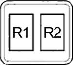
| Relay | ||
| R1 | Digital Motor Electronics (DME) Main Relay | |
| R2 | Ignition and Fuel Injection | |
| R3 | Valvetronic | |
| R4 | Transmission Oil Pump | |
| R5 | Power Supply Sensors/Actuators | |
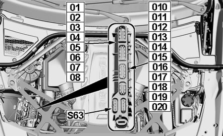
Integrated Supply Module (B57 – xDrive30d, xDrive40d & M50d)
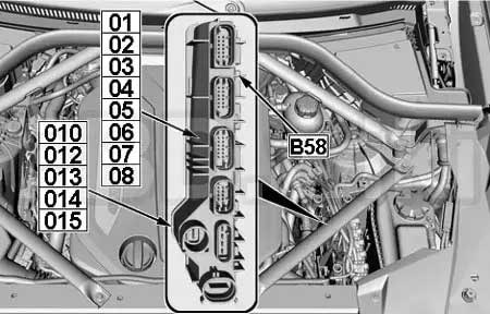
The integrated supply module contains fuses and relays. If one of the fuses or one of the relays is faulty, the complete integrated supply module must be renewed.
| No. | A | Protected Component |
| 01 | 7.5 | Oil Level Sensor, Oil Pressure Control Valve, Fuel Quantity Control Valve |
| 02 | 5 | Piston Cooling Solenoid Valve |
| 03 | 10 | Engine Mount Changeover Valve, Oxygen Sensor after Catalytic Converter |
| 04 | 15 | Oxygen Sensor before Catalytic Converter |
| 05 | 20 | B57 TOP: Compressor Bypass Plate Changeover Valve, Turbine Control Flap Pressure Converter |
| 20 | B57S: High Pressure Compressor Actuating Flap Changeover Valve, Changeover Valve of Turbine Control Flap | |
| 06 | 20 | Pressure Converter for Wastegate Valve, Low Pressure Compressor Bypass Flap Changeover Valve, Coolent Pump Changeover Valve (except B57S), EGR Cooler Bypass Flap Changeover Valve, Nitrogen Oxide Sensor before SCR Catalytic Converter, Nitrogen Oxide Sensor after SCR Catalytic Converter |
| 07 | 15 | Diesel Particulate Sensor, Low Pressure Exhaust-Gas Recirculation Exhaust Back Pressure Flap |
| 08 | 10 | Digital Diesel Electronics (DDE), Engine Breather Heater, Rail Pressure Regulating Valve |
| 09 | – | – |
| 010 | 30 | Digital Diesel Electronics (DDE) |
| 011 | – | – |
| 012 | 40 | Fuel Filter Heating |
| 013 | 15 | Digital Diesel Electronics (DDE) |
| 014 | 40 | Digital Diesel Electronics (DDE) |
| 015 | 30 | Digital Diesel Electronics (DDE) |
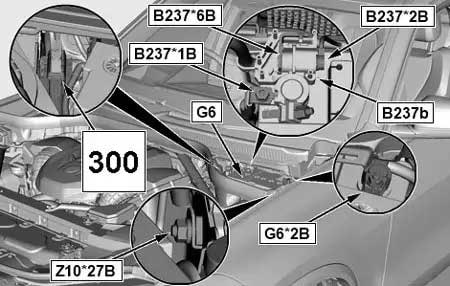
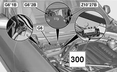
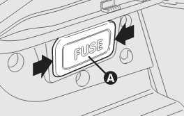
Additional Fuse Holder
Location:
RHD

LHD

| No. | A | Protected Component |
| 300 | 60 | Power Control Unit |
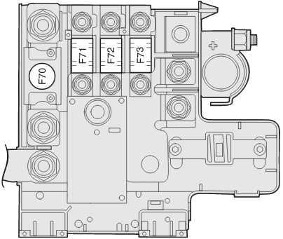
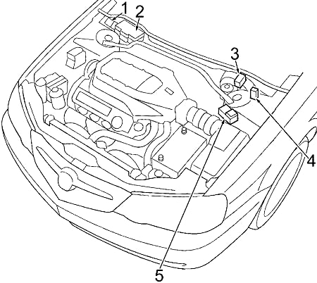
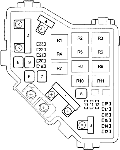
Power Distribution Box (Engine Compartment)
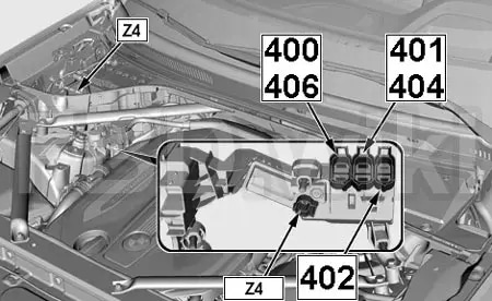
The integrated supply module contains fuses. If one of the fuses is faulty, the complete supply module must be renewed.
| No. | A | Protected Component |
| 400 | 80 | Fan 400W, 600W: Electric Fan Cut-Out Relay |
| 125 | Fan 850W: Electric Fan Cut-Out Relay |
|
| 150 | Fan 1000W: Electric Fan Cut-Out Relay | |
| 401 | 150 | Electromechanical Power Steering |
| 402 | 100 | Front Electric Auxiliary Heater |
| 403 | – | – |
| 404 | 80 | Dynamic Stability Control (DSC) |
| 405 | – | – |
| 406 | 125 | Integrated Supply Module |
Power Distribution Box
with Recovery System
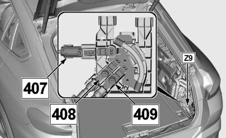
without Recovery System
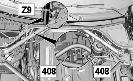
The integrated supply module contains fuses. If one of the fuses is faulty, the complete supply module must be renewed.
| No. |
A |
Protected Component |
| 407 | 60 | Power Control Unit |
| 408 | 125 | Front Electric Active Roll Stabilisation (Dynamic Drive) |
| 409 | 125 | Rear Electric Active Roll Stabilisation (Dynamic Drive) |
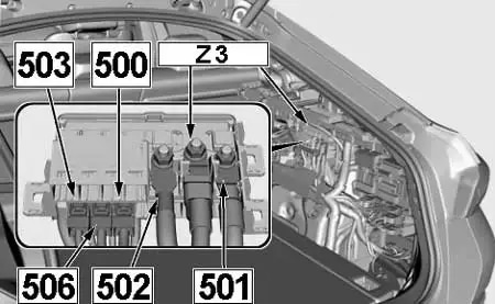
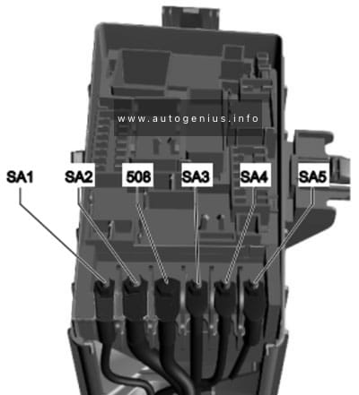
Power Distribution Box No.2 (Luggage Compartment)
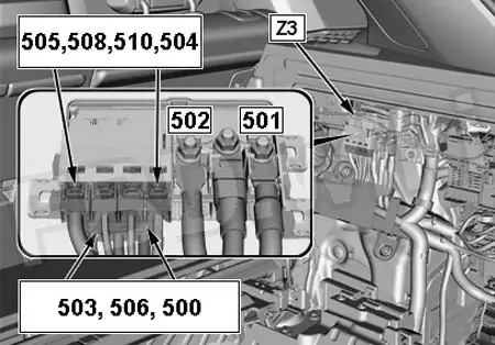
| No. |
A |
Protected Component |
| 500 | 50 | Booster |
| 501 | 250 | Rear Power Distribution Box (Luggage Fuse Box) |
| 502 | 250 | Front Right Power Distribution Box (Passenger Compartment Fuse Box No.2) |
| 503 | – | – |
| 504 | 60 | Body Domain Controller |
| 505 | – | – |
| 506 | 80 | Rear Axle King Pin Inclination Control (Integral Active Steering) |
| 508 | 60 | Power Control Unit |
| 510 | 40 | Electronic Ride-Height Control |
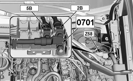
48 Volt Power Distribution Box

| No. |
A |
Protected Component |
| 0701 | 150 | Power Control Unit 48 Volt |
WARNING: Terminal and harness assignments for individual connectors will vary depending on vehicle equipment level, model, and market.