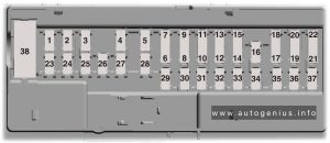
Dodge Durango (2004 – 2009) – fuse box diagram

Dodge Durango (2004 – 2009) – fuse box diagram

Year of  production: 2004, 2005, 2006, 2007, 2008, 2009

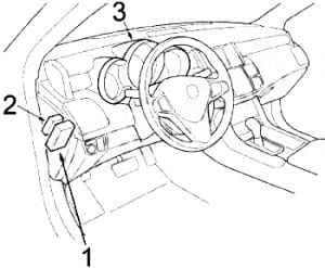
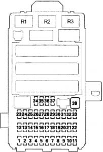
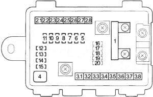
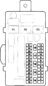
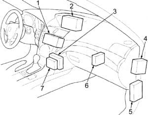
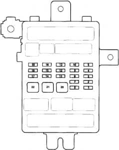
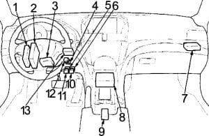
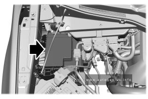
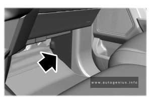
Passenger Compartment Fuse Box

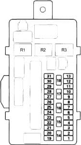
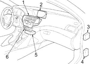
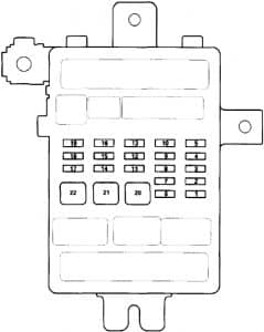
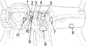
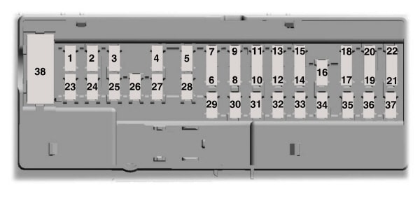
Dodge Durango - fuse box diagram - passenger compartment
Dodge Durango – fuse box diagram – passenger compartment
No. A
Circuit Protected
1  –
2 10 Power Mirror
3 20 Power Outlet – Instrument Panel
4  –
5  –
6  –
7 25 Radio Amplifier
8 10 Mirror Switch, Mirror Memory Module
9 20 Cluster
10 15 Cluster
11 10 Satellite Receiver, Monitor/DVD Media System
12 25 Radio
13 15 A/C Heater Control (Automatic A/C)
14 15 Electronic Overhead Module, Data Link Connector, Hands-Free Module, Sentry Key Remote Entry Module, Air Conditioner Compressor Clutch Relay, Fuel Pump Relay, Powertrain Control Module
15  –
16 10 Occupant Classification Module, Occupant Restraint Controller Module, Passenger Airbag On/Off Indicator Lamp
17  –
18 10 Sentry Key Remote Entry Module, Integrate Power Module, Air Conditioner Compressor Clutch Relay, Fuel Pump Relay, Powertrain Control Module
19 10 Cluster, Transfer Case Selector Switch, Driver/Passenger Heated Seat Switch, Inside Rearview Mirror, Infrared Sensor
20  –
21  –
22  –
23  –
24 10 A/C Heater Control (Manual A/C), Rear A /C Heater Control (Automatic A/C), Rear Blower Motor Relay, Rear Window Defogger Relay
25 10 Occupant Restraint Controller Module
26 10 ABS, Stop Lamp Inhibit (Traction Control), Steering Angle Sensor (Traction Control), Dynamics Sensor (Traction Control)
27  –
28  –
29  –
30  –
31  –
32 10 ’03-’04: Starter Relay, Powertrain ControlModule, Cluster
33 10 Occupant Classification Module
36 10 Powertrain Control Module, Cluster
35 20 Power Outlet – Console, Rear Power Outlet
Circuit Breaker
CB1 25 Sunroof Motor, Power Window
CB2  –
Relay
R1 Rear Window Defogger
R2 Rear Blower Motor
R3 Accessory
R4  –

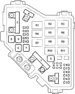
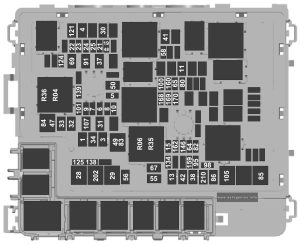
Integrated Power Module

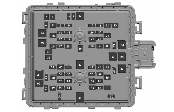
Dodge Durango - fuse box diagram - integrated power module
Dodge Durango – fuse box diagram – integrated power module
No. A
Circuit Protected
8 10 Left Front Park/Turn Lamp, Left Front Marker Side Lamp, Left Tail/Stop/Turn Lamp, License Lamp
9 10 Trailer Tow Connector
10 10 Right Front Park/Turn Lamp, Right Front Marker Side Lamp, Right Tail/Stop/Turn Lamp
12 20 Front Control Module
13 20 Front Control Module
14 20 Adjustable Pedals Relay
15 20 Fog Lamp Relay
16 20 Horn Relay
17 20 Wiper Rear Relay
18 20 Front Control Module
19 20 ’05-’09: Left Trailer Tow Relay (Trailer Tow Brake Lamp Relay Control, Trailer Connector)
15 ’03-’04: Left Trailer Tow Relay (Trailer Tow Brake Lamp Relay Control, Trailer Connector)
20 20 Front Control Module
21 20 ’05-’09: Right Trailer Tow Relay (Trailer Tow Brake Lamp Relay Control, Trailer Connector)
15 ’03-’04: Right Trailer Tow Relay (Trailer Tow Brake Lamp Relay Control, Trailer Connector)
22 30 Front Control Module
23 40 Radiator Fan (High) Relay, Radiator Fan (Low) Relay
27 30 Front Control Module, Fuse (Passenger Compartment): “11”, “12”
28 30 Fuse (Passenger Compartment): “13”, “14”
Relay
R1 Wiper On/Off
R2 Wiper High/Low
R3 Horn
R4 Wiper Rear
R5 Left Trailer Tow
R6 Right Trailer Tow
R7 Park Lamp
R8 Radiator Fan (High)
R9 Radiator Fan (Low)
R10 Fog Lamp
R11 Adjustable Pedals

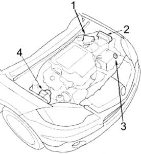
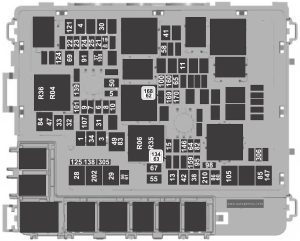
Engine Compartment Fuse Box

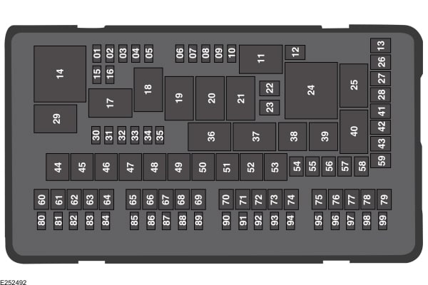
Dodge Durango - fuse box diagram - engine compartment
Dodge Durango – fuse box diagram – engine compartment
No. A
Circuit Protected
1 30 Starter Relay, Ignition Switch (Fuse (Passenger Compartment): “16”, “18”, “19”, “32”, “34”; (Engine Compartment): “16”), Run/Start Relay
2 30 Integrate Power Module (Wiper High/Low Relay, Wiper On/Off Relay)
3 40 Brake Provision Module
4 30 Ignition Switch (Fuse (Passenger Compartment): “25”), Sunroof Motor, Fuse (Passenger Compartment): “35”
5 40 ’05-’09: Driver/Passenger Seat Switch, Heated Seat Module, Seat Memory Module
50 ’03-’04: Driver/Passenger Seat Switch, Heated Seat Module, Seat Memory Module
6 20 Ignition Switch (Fuse (Passenger Compartment): “24”, “25”, “26”)
7 40 Front Blower Motor Relay, Run/Remote Relay
8 40 Accessory Relay (Circuit Breaker, Fuse (Passenger Compartment): “3”)
9  –
10 30 Automatic Shut Down Relay (Powertrain Control Module, ASD Relay, Ignition Coil, Fuel Injector, Ignition Capacitor)
11 40 ’05-’09: Liftgate Power Module
12 40 Rear Window Defogger Relay (Fuse (Passenger Compartment): “2”), Shift Motor/Mode Sensor Assembly
13 30 Rear Blower Motor Relay
14 40 ABS
15 50 Fuse (Passenger Compartment): “7”, “8”, “9”, “10”, “33”
16 10 ’05-’09: Starter Relay, Cluster, Powertrain Control Module, Front Control Module
17  –
18 20 Fuel Pump Relay
19 20 Transmission Control Relay
20  –
21 20 ABS
22 20 Powertrain Control Module
23 20 Trailer Tow Connector
24 15 Air Conditioner Compressor Clutch Relay
25 15 Stop Lamp Switch
26  –
27 10 Ignition Switch (Instrument Cluster)
28  –
Relay
R1 ’05-’09: Run/Start
R2 ’05-’09: Run/Remote
R3  –
R4 Starter
R5 Transmission Control
R6 Air Conditioner Compressor Clutch
R7 Fuel Pump
R8 ’05-’09: Stop Lamp Inhibit (Traction Control)
R9 Front Blower Motor
R10 Automatic Shut Down

WARNING: Terminal and harness assignments for individual connectors will vary depending on vehicle equipment level, model, and market.

Dodge Dakota (2000 – 2004) – fuse box diagram

Dodge Dakota (2000 – 2004) – fuse box diagram

Year of production: 2000, 2001, 2002, 2003, 2004

Passenger Compartment Fuse Box

Dodge Dakota - fuse box diagram - passenger compartment
Dodge Dakota – fuse box diagram – passenger compartment
No.
A
Protected Component
1 15 Sentry Key Immobilizer Module, Instrument Cluster, Dome Lamp, Glove Box Lamp and Switch, Driver Door Module, Data Link Connector, Overhead Console, Cargo Lamp, Radio (’00-’01), Center Console Lamp (’00-’01)
2 20 Horn Relay
3 20 Radio (’02-’04)
4 20 Park Lamp Relay (Front Park/Turn Signal Lamp, Front Side Marker Lamp, License Lamp, Rear Tail/Stop/Turn Signal Lamp, Central Timer Module, Fuse (Engine Compartment): “T”)
5 20 Front Wiper Relay, Central Timer Module, Multi-Function Switch, Wiper Motor
6  –
7  –
8 10 Instrument Cluster, Powertrain Control Module, Transmission Control Module
9 5 Instrument Cluster, A/C Heater Control, Radio, Transfer Case Selector Switch, Overhead Console, Shift Bezel Lamp, Cigar Lighter
10 10 Powertrain Control Module, Fuel Pump Relay, Radiator Fan Relay, Sentry Key Immobilizer Module
11 10 Air Conditioner Compressor Clutch Relay, Automatic Day/Night Mirror, Overhead Console, Central Timer Module, Transfer Case Selector Switch, Duty Cycle EVAP/Purge Solenoid (’00-’01)
12 10 Starter Relay, Powertrain Control Module
13 20 Amplifier (’02-’04)
15 Amplifier (’00-’01)
14 10 Instrument Cluster
15 10 Power Mirror
16  –
17 15 Cigar Lighter/Power Outlet
18 10 Radio
19 10 Combination Flasher
20 10 Airbag Control Module, Passenger Airbag On/Off Switch
21 10 Airbag Control Module
22  –
23  –
24 15 Rear Window Defogger Relay
25 10 Heating and Air Conditioning Control
26 15 Back-Up Lamp, Transmission Solenoid/TRS Assembly (4.7L + Automatic Transmission), Back-Up Lamp Switch (Manual Transmission), Passenger Door Power Lock Switch, Automatic Day/Night Mirror, Trailer Tow Connector
27 10 ABS
28 25 Driver Door Module (Power Window)
29  –
Relay
R1 Horn
R2 Park Lamp

Engine Compartment Fuse Box

Dodge Dakota - fuse box diagram - engine  compartment
Dodge Dakota – fuse box diagram – engine compartment
No.
A
Protected Component
1 20 Combination Flasher (’02-’04)
30 Combination Flasher (’00-’01)
2 20 Fuel Pump Relay, Powertrain Control Module
3 20 Central Timer Module
4 40 Rear Window Defogger Relay, Fuse (Passenger Compartment): “15”
5 20 Stop Lamp Switch
6 30 Electric Brake (Triler Tow)
7 40 Fuse (Passenger Compartment): “1”, “2”, “3”, “4”, “13”)
8 40 ABS
9 50 Ignition Switch (Fuse (Passenger Compartment): “21”, “24”, “25”, “26”, “27”)
10 40 Ignition Switch (Fuse (Passenger Compartment): “17”, “18”, “19”)
11 30 Automatic Shut Down Relay (Powertrain Control Module, Capacitor, Ignition Coil, Fuel Injector)
12 20 Central Timer Module
13 40 Ignition Switch (Blower Motor)
14 50 Power Seat Switch
15 40 Radiator Fan Relay
50 Radiator Fan Relay
16 50 Starter Relay
17 50 Ignition Switch (Fuse (Passenger Compartment): “5”, “28”)
18  –
A 20 Transfer Case Control Module
B 10 Air Conditioner Compressor Clutch Relay
C 20 Trailer Tow Connector
D 20 Center Power Outlet
E 20 Ignition Switch (Fuse (Passenger Compartment): “8”, “10”, “11”, “12”, “14”,”20″)
F 20 Transmission Control Relay (Transmision Range Sensor (3.7L), Transmission Solenoid/Pressure Switch Assembly (3.7L), Transmission Solenoid/TRS Assembly (4.7L), Powertrain Control Module)
G  –
H 20 Fog Lamp Relay (Fog Lam, Headlamp Switch, Central Timer Module)
J  –
K  –
L  –
M  –
N  –
P  –
R  –
S  –
T 10 Trailer Tow Connector
U 20 Oxygen Sensor
TRelay
R1 Radiator Fan
R2 Automatic Shut Down
R3  –
R4  –
R5  –
R6 EBL
R7 Fuel Pump
R8  –
R9 Air Conditioner Compressor Clutch
R10 Fog Lamp
R11  –
R12 Oxygen Sensor
R13  –
R14 Transmission Control
R15  –
R16  –
R17 Starter
R18 Wiper
R19  –

WARNING: Terminal and harness assignments for individual connectors will vary depending on vehicle equipment level, model, and market.
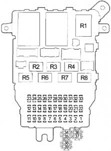
Dodge Dakota (1991 – 1996) – fuse box diagram

Dodge Dakota (1991 – 1996) – fuse box diagram

Year of production: 1991, 1992, 1993, 1994, 1995, 1996

Passenger Compartment Fuse Box

Dodge Dakota - fuse box diagram - passenger compartment
Dodge Dakota – fuse box diagram – passenger compartment
No.
A
Protected Component
1 30 Blower Motor
2 30 Circuit Breaker: Power Window
3 15 Airbag Control Module, Overhead Console, Automatic Day/Night Mirror, Back-Up Lamp Switch, Powertrain Control Module (2.5 L.), Park/Neutral Position Switch
4 5 ABS Warning Lamp Relay (ABS Control Module, ABS Power Relay)
5 20 Door Lock Switch
6 20 Radio Choke Relay, Horn Relay, Instrument Cluster
7 10 Combination Buzzer, Stop Lamp Switch, Rear Wheel Anti-Lock Control Module
8 20 Headlamp Switch
9 15 Cigar Lighter
10 20 Intermittent Wiper Control Module, Wiper Switch, Windshield Wiper Motor
11 20 Rear Wheel Anti-Lock Control Module, Turn Signal Flasher
12 10 Radio
13 4 Instrument Cluster, Transmission Overdrive Switch, Overhead Console, Radio, Cigar Lighter Lamp, ASH Raceiver Lamp, HVAC Switch
14 15 Instrument Cluster, Airbag Control Module
15 2 Vehicle Speed Control Switch
16 5 Combination Buzzer, 4WD Indicator Lamp, Transmission Oil Temperature Lamp, Transmission Overdrive Switch
17  –
18  –
19  –
20 25 Off-Road Lamp Switch, Park Lamp Relay
Relay
R1 Combination Buzzer
R2 Hazard Flasher
R3 Horn
R4 Time Delay
R5 Turn Signal Flasher
R6 ABS Warning Lamp

Engine Compartment Fuse Box

Dodge Dakota - fuse box diagram - engine compartment
Dodge Dakota – fuse box diagram – engine compartment
No.
A
Protected Component
F1 20 Hazard Flasher
F2 5 Time Delay Relay, Underhood Lamp
A 40 ABS Power Relay
B 30 Starter Relay, Radiator Fan Control Relay (2.5L), Air Conditioner Compressor Clutch Relay
C 40 Ignition Switch (Fuse (Passenger Compartment): “14”, “15”, “15”)
D 30 Auto Shut Down Relay, Powertrain Control Module, Fuel Pump Relay (3.9L, 5.7L)
E 50 Ignition Switch (Fuse (Passenger Compartment): “1”, “2”, “3”, “4”), Clutch Pedal Position Switch, Fuel Pump Relay (3.9L, 5.7L), Auto Shut Down Relay, Radiator Fan Control Relay (2.5L), Air Conditioner Compressor Clutch Relay, Starter Relay
F 20 Fuse: “F2”
G 50 Headlamp Switch, Fuse (Passenger Compartment): “5”, “6”, “7”, “8”, “20”
H  –
Relay
R1 Starter
R2 Air Conditioner Compressor Clutch
R3 Auto Shut Down
R4 2.5 L: Radiator Fan Control
R5 3.9 L, 5.2 L: Fuel Pump
R6 ABS Power

WARNING: Terminal and harness assignments for individual connectors will vary depending on vehicle equipment level, model, and market.
Dodge Dakota (1997 – 2000) – fuse box diagram

Dodge Dakota (1997 – 2000) – fuse box diagram

Year of production: 1997, 1998, 1999, 2000

Passenger Compartment Fuse Box

Dodge Dakota - fuse box diagram - passenger compartment
Dodge Dakota – fuse box diagram – passenger compartment
No.
A
Protected Component
1 20 Headlamp Flasher Relay, Air Conditioner Compressor Clutch Relay, Horn Relay, Central Timer Module (VTSS)
2 15 Park/Neutral Position Switch (Automatic Transmission), Back-Up Lamp Switch (Manual Transmission)
3 10 ABS
4 15 Instrument Cluster
5 5 A/C Heater Control, Heater Control (except A/C), Ash Receiver Lamp, Radio, Instrument Cluster
6 20 Wiper Relay, Multi-Function Switch, Central Timer Module, Wiper Motor
7 15 Blower Motor Relay, Air Conditioner Compressor Clutch Relay
8 10 Radio
9 10 Diesel: Engine Control Module, Fuel Heater Relay
10 Gasoline: Powertrain Control Module, Fuel Pump Relay, Automatic Shut Down Relay, Radiator Fan Relay
10 15 Combination Flasher
11 10 EVAP/Purge Solenoid, Overhead Console, Central Timer Module
12 15 Glove Box Lamp, Radio, Data Link Connector, Underhood Lamp/Switch, Dome Lamp, Overhead Console, Power Mirror Switch
13 20 Central Timer Switch, Power Window/Door Lock Switch
14 15 Headlamp Switch (City Lamp, Tail/Stop Lamp, License Lamp, A/C Heater Control, Heater Control (except A/C), Ash Receiver Lamp, Radio, Instrument Cluster)
15 15 Cigar Lighter
16  –
17 10 Instrument Cluster
18 10 Airbag Control Module
19 10 Airbag Control Module, Passenger Airbag On/Off Switch
Circuit Breaker
20 25 Power Window/Door Lock Switch
21  –
Relay
R1 Horn
R2 Combination Flasher

Engine Compartment Fuse Box

Dodge Dakota - fuse box diagram - engine compartment
Dodge Dakota – fuse box diagram – engine compartment
No.
A
Protected Component
A 25 Diesel: Air Conditioner Compressor Clutch Relay, Engine ControlModule, Powertrain Control Module, Electric Vacuum Modulator
15 Gasoline: Oxygen Sensor
B 15 Left Headlamp
C 20 Fog Lamp Relay
D 25 Combination Flasher
E 20 Stop Lamp Switch
F 10 Diesel: Automatic Shut Down Relay, Powertrain Control Module
20 Gasoline: Transmission Control Relay
G 15 Right Headlamp
1 50 Diesel: Fuel Heater Relay
20 Gasoline: Powertrain Control Module, Fuel Pump Relay
2 20 Diesel: Power Outlet
30 Gasoline: Radiator Fan Relay
3 50 Diesel: Automatic Shut Down Relay (Fuel Injection Pump, Glow Plug Relay, Fuse: “A”)
30 Gasoline: Automatic Shut Down Relay (Fuel Injector, Ignition Coil, Powertrain Control Module, Fuse: “A”)
4 50 Diesel: Glow Plug Relay
20 Gasoline: Power Outlet
5 40 Blower Motor Relay
6 50 Diesel: Glow Plug Relay
7 50 Fuse (Passenger Compartment): “1”, “4”, “12”, “13”, “14”, “21”
8 30 ABS
9 40 Starter Relay, Ignition Switch (Fuse (Passenger Compartment): “2”,”3″, “7”, “18”, “20”), Radiator Fan Relay, Fuel Pump Relay, Automatic Shut Down Relay
10 40 Ignition Switch (Starter Relay, Fuse (Passenger Compartment): “6”, “8”, “9”, “10”, “11”, “15”, “16”, “17”, “19”)
11 140 Generator
Relay
R1 Wiper
R2 Blower Motor
R3 Starter
R4  –
R5 Fog Lamp
R6  –
R7 Gasoline: Transmission Control
R8 Air Conditioner Compressor Clutch
R9 Automatic Shut Down
R10  –
R11 Gasoline: Radiator Fan
R12 Headlamp Flasher
R13 Gasoline: Fuel Pump

Engine Compartment Relay Box

Dodge Dakota - fuse box diagram - engine relay box
Dodge Dakota – fuse box diagram – engine relay box
No.
A
Protected Component
1  –
2  –
3  –
4  –
Relay
R1  –
R2 Fuel Heater Relay
R3  –
R4  –

WARNING: Terminal and harness assignments for individual connectors will vary depending on vehicle equipment level, model, and market.
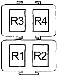
Dodge Charger (2005 – 2010) – fuse box diagram

Dodge Charger (2005 – 2010) – fuse box diagram

Year of production: 2005, 2006, 2007, 2008, 2009, 2010

Luggage Compartment Fuse Box

Dodge Charger - fuse box diagram - luggage compartment
Dodge Charger – fuse box diagram – luggage compartment
No. A
Protected Component
1 60 Fuse (Luggage Compartment): “14”, “36”, “38”, “44”
2 40 Engine Compartment Fuse Box (Fusible Link 14)
3 20 Police: Dome Lamp
4 40 Engine Compartment Fuse Box (Fusible Link 14)
5 30 except for SRT8: Heated Seat Module, Zener Diode, Fuse (Luggage Compartment): “30”
40 SRT8: Heated Seat Module, Zener Diode, Fuse (Luggage Compartment): “30”
6 20 Fuel Pump Relay
7 20 SRT8: Subwoofer Amplifier
15 Police: Spot Lamp (Right)
8 15 Data Link Connector, Occupant Classification System (LHD), Ignition Switch (Engine Control Module (Diesel), Powertrain Control Module, Lock Steering Column Module (RHD), Fuel Pump Relay (Gasoline), Fuse (Luggage Compartment): “27”, “29”, “40”, Diode No.1)
9 20 Power Outlet – Console
10 10 Export: Rear Fog Lamp Relay
15 Police: Spot Lamp (Left)
14 10 A/C / Heater Control, Sentry Key Remote Entry Module (LHD), Cluster, Intrusion Transceiver  Module (RHD)
15 20 Brake Module (Trailer Tow)
16 20 Magnum (300C Touring): Rear Power Outlet
17 20 Cluster, Lock Steering Column Module (RHD), Sentry Key Remote Entry Module (RHD)
18 20 Cigar Lighter
19 10 Stop Lamp Switch, Stop Lamp Inhibit Relay (except MK25E)
20 20 Magnum (300C Touring): Rear Wiper Relay
27 10 Occupant Classification System, Occupant Restraint Controller Module
28 10 except for SRT8: Occupant Restraint Controller Module
5 SRT8: Occupant Restraint Controller Module
29 5 Stop Lamp Switch, Cluster, Sentry Key Remote Entry Module, Mass Air Flow Sensor (Diesel), ABS, Front Control Module, Powertrain Control Module (Gasoline), Engine Control Module (Diesel)
30 10 Driver/Passenger Door Module, Mirror Switch, Steering Control Module, Police/Taxi Interface Module
35 5 Mirror Switch (except Memory), Passenger Express Window/Door Lock Switch (except Base), Backlite Antenna Amplifier, Headlamp Flasher (Police), Police Relay No.1, Police Relay No.2, Police Relay No.3, Electronic Overhead Module (Export), Rain Sensor (Export)
36 20 Radio, Hands-Free Module, Satellite Receiver, Monitor/DVD Media System, Traffic Information Receiver Module (Export)
37 15 NAG1: Transmission Control Module
38 5 Cargo Lamp (except Magnum), Analog Clock Module, Electronic Overhead Module, Siren (RHD)
39 10 Heated Mirror
40 5 except for SRT8: Left/Right Heated Seat Switch, A/C Heater Control, Inside Rearview Mirror
10 SRT8: Left/Right Heated Seat Switch, A/C Heater Control, Inside Rearview Mirror
5 Police: Bank Switch
41 10 A/C Heater Control, Tire Pressure Monitor, Left/Right Headlamp Level Sensor (Export), Parl Assist Module, Headlamp Leveling Module (Export), Left/Right High-Intensity Discharge Lamp (Export)
42 30 Front Blower Motor (MTC), Front Blower Module (ATC)
43 30 Rear Window Defogger
44 20 Front Control Module, Sunroof Motor/Module, Radio Amplifier
Circuit Breaker
CB1 25 Driver Seat Switch (except Memory), Memory Seat Module, Cluster (except Power/Memory Seat)
CB2 25 Passenger Seat Switch
CB3 25 except for SRT8:Driver/Passenger Window/Door Lock Switch (Base), Driver/Passenger Door Module (except Base), Driver Express Window/Door Lock Switch (except Base)
30 SRT8:Driver/Passenger Window/Door Lock Switch (Base), Driver/Passenger Door Module (except Base), Driver Express Window/Door Lock Switch (except Base)
Diode
D1 NAG1: Transmission Control Relay
D2 Front Control Module
D3 Zener
Relay
R1 Run
R2 Rear Window Defogger
R3 Accessory Delay
R4 NAG1: Transmission Control
R5 Export: Rear Fog Lamp
R6 Magnum (300C Touring): Rear Wiper
R7  –
R8 Stop Lamp Inhibit (except MK25E)
R9 Fuel Pump
R10  –

Engine Compartment Fuse Box

Dodge Charger - fuse box diagram - engine compartment
Dodge Charger – fuse box diagram – engine compartment
No. A
Protected Component
1 20 HID: Left High-Intensity Discharge Lamp
2 20 HID: Right High-Intensity Discharge Lamp
3 15 Adjustable Pedals Relay (except Memory)
4 20 Horn Relay, Front Control Module, Air Conditioner Compressor Clutch (Gasoline)
5 20 HID: Headlamp Washer Relay
20 Cluster (’05)
20 Police: Underhood Lamp
6 15 Front Control Module
7 20 Front Fog Lamp, Front Control Module
8 15 Park Lamp Relay (Front Park/Turn Lamp, Front/Rear Side Marker Lamp, License Lamp, Tail/Stop Lamp or Tail/Stop/Park Lamp), Front Control Module
9 15 Front Control Module
10 5 Powertrain Control Module, Starter Relay, Engine Control Module (Diesel)
11 15 SRT8: Powertrain Control Module
20 except for SRT8: Powertrain Control Module
12  –
13  –
14 20 SRT8: Powertrain Control Module
25 except for SRT8: Powertrain Control Module
20 ’05: Powertrain Control Module
25 Diesel: Engine Control Module, PTC Relay No.1, PTC Relay No.2, PTC Relay No.3
15 25 Gasoline (except SRT8): Fuel Injector, Ignition Coil, Ignition Capacitor, Short Runner Valve Solenoid (3.5L)
20 ’05: Fuel Injector, Ignition Coil, Ignition Capacitor
20 SRT8: Fuel Injector, Ignition Coil, Ignition Capacitor
25 Diesel: Engine Control Module, Glow Plug Module, Oxygen Sensor, Intake Swirl Servo Motor, Crankcase Vent Heater, EGR Valve, Boost Pressure Servo Motor, Air Conditioner Compressor Clutch, Fuel Pump Relay,
16 15 Diesel: Engine Control Module
20 ’05: Powertrain Control Module
17 30 ABS
18 30 Wiper On/Off Relay
19 50 Radiator Fan (High) Relay, Radiator Fan Control (High/Low) Relay, Front Control Module
20 20 Starter Relay
21 50 ABS
22 40 Radiator Fan Control Relay, Air Conditioner Compressor Clutch
23 50 HID: High Intensity Discharge Lamp Relay (Fuse (Engine Compartment): “1”, “2”)
24 60 AWD/SRT/Diesel: Fan Radiator
25 30 Front Control Module
26 20 RLE: Transmission Control Relay
20 Diesel: Air Conditioner Compressor Clutch Relay
27 30 Front Control Module
Relay
R1 Horn
R2 Gasoline: Air Conditioner Compressor Clutch
R3 Radiator Fan Control (High/Low)
R4 Radiator Fan (High)
R5 Wiper On/Off
R6 RLE: Transmission Control
R7 Radiator Fan Control
R8 Wiper High/Low
R9 Starter
R10 Adjustable Pedals (except Memory)
R11 Park Lamp
R12 Front Fog Lamp
R13 Auto Shut Down
R14 High Intensity Discharge Relay
R15  –


Relay Box (Diesel)

Dodge Charger - fuse box diagram - relay box (diesel)
Dodge Charger – fuse box diagram – relay box (diesel)

A
Protected Component
1 50 PTC No.1 Relay
2 50 PTC No.2 Relay
3 50 PTC No.3 Relay
Relay
R1 PTC No.3
R2 PTC No.2
R3 PTC No.1


Relay Box (Police)

Dodge Charger - fuse box diagram - relay box (police)
Dodge Charger – fuse box diagram – relay box (police)

A
Protected Component
1 20 Police Accessories
2 20 Police Relay No.1 (Police Accessories)
3 20 Police Accessories
4 20 Police Relay No.3 (Police Accessories)
5 20 Police Accessories
6 20 Police Relay No.2 (Police Accessories)
7  –
8  –
Relay
R1 Police No.1
R2 Police No.3
R3 Police No.2
R4  –

WARNING: Terminal and harness assignments for individual connectors will vary depending on vehicle equipment level, model, and market.
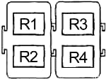
Dodge Magnum (2005 – 2010) – fuse box diagram

Dodge Magnum (2005 – 2010) – fuse box diagram

Year of production: 2005, 2006, 2007, 2008, 2009, 2010

Luggage Compartment Fuse Box

Dodge Ma0gnum - fuse box diagram - luggage compartment
Dodge Ma0gnum – fuse box diagram – luggage compartment
No. A
Protected Component
1 60 Fuse (Luggage Compartment): “14”, “36”, “38”, “44”
2 40 Engine Compartment Fuse Box (Fusible Link 14)
3 20 Police: Dome Lamp
4 40 Engine Compartment Fuse Box (Fusible Link 14)
5 30 except for SRT8: Heated Seat Module, Zener Diode, Fuse (Luggage Compartment): “30”
40 SRT8: Heated Seat Module, Zener Diode, Fuse (Luggage Compartment): “30”
6 20 Fuel Pump Relay
7 20 SRT8: Subwoofer Amplifier
15 Police: Spot Lamp (Right)
8 15 Data Link Connector, Occupant Classification System (LHD), Ignition Switch (Engine Control Module (Diesel), Powertrain Control Module, Lock Steering Column Module (RHD), Fuel Pump Relay (Gasoline), Fuse (Luggage Compartment): “27”, “29”, “40”, Diode No.1)
9 20 Power Outlet – Console
10 10 Export: Rear Fog Lamp Relay
15 Police: Spot Lamp (Left)
14 10 A/C / Heater Control, Sentry Key Remote Entry Module (LHD), Cluster, Intrusion Transceiver  Module (RHD)
15 20 Brake Module (Trailer Tow)
16 20 Magnum (300C Touring): Rear Power Outlet
17 20 Cluster, Lock Steering Column Module (RHD), Sentry Key Remote Entry Module (RHD)
18 20 Cigar Lighter
19 10 Stop Lamp Switch, Stop Lamp Inhibit Relay (except MK25E)
20 20 Magnum (300C Touring): Rear Wiper Relay
27 10 Occupant Classification System, Occupant Restraint Controller Module
28 10 except for SRT8: Occupant Restraint Controller Module
5 SRT8: Occupant Restraint Controller Module
29 5 Stop Lamp Switch, Cluster, Sentry Key Remote Entry Module, Mass Air Flow Sensor (Diesel), ABS, Front Control Module, Powertrain Control Module (Gasoline), Engine Control Module (Diesel)
30 10 Driver/Passenger Door Module, Mirror Switch, Steering Control Module, Police/Taxi Interface Module
35 5 Mirror Switch (except Memory), Passenger Express Window/Door Lock Switch (except Base), Backlite Antenna Amplifier, Headlamp Flasher (Police), Police Relay No.1, Police Relay No.2, Police Relay No.3, Electronic Overhead Module (Export), Rain Sensor (Export)
36 20 Radio, Hands-Free Module, Satellite Receiver, Monitor/DVD Media System, Traffic Information Receiver Module (Export)
37 15 NAG1: Transmission Control Module
38 5 Cargo Lamp (except Magnum), Analog Clock Module, Electronic Overhead Module, Siren (RHD)
39 10 Heated Mirror
40 5 except for SRT8: Left/Right Heated Seat Switch, A/C Heater Control, Inside Rearview Mirror
10 SRT8: Left/Right Heated Seat Switch, A/C Heater Control, Inside Rearview Mirror
5 Police: Bank Switch
41 10 A/C Heater Control, Tire Pressure Monitor, Left/Right Headlamp Level Sensor (Export), Parl Assist Module, Headlamp Leveling Module (Export), Left/Right High-Intensity Discharge Lamp (Export)
42 30 Front Blower Motor (MTC), Front Blower Module (ATC)
43 30 Rear Window Defogger
44 20 Front Control Module, Sunroof Motor/Module, Radio Amplifier
Circuit Breaker
CB1 25 Driver Seat Switch (except Memory), Memory Seat Module, Cluster (except Power/Memory Seat)
CB2 25 Passenger Seat Switch
CB3 25 except for SRT8:Driver/Passenger Window/Door Lock Switch (Base), Driver/Passenger Door Module (except Base), Driver Express Window/Door Lock Switch (except Base)
30 SRT8:Driver/Passenger Window/Door Lock Switch (Base), Driver/Passenger Door Module (except Base), Driver Express Window/Door Lock Switch (except Base)
Diode
D1 NAG1: Transmission Control Relay
D2 Front Control Module
D3 Zener
Relay
R1 Run
R2 Rear Window Defogger
R3 Accessory Delay
R4 NAG1: Transmission Control
R5 Export: Rear Fog Lamp
R6 Magnum (300C Touring): Rear Wiper
R7  –
R8 Stop Lamp Inhibit (except MK25E)
R9 Fuel Pump
R10  –

Engine Compartment Fuse Box

Dodge Magnum - fuse box diagram - engine compartment
Dodge Magnum – fuse box diagram – engine compartment
No. A
Protected Component
1 20 HID: Left High-Intensity Discharge Lamp
2 20 HID: Right High-Intensity Discharge Lamp
3 15 Adjustable Pedals Relay (except Memory)
4 20 Horn Relay, Front Control Module, Air Conditioner Compressor Clutch (Gasoline)
5 20 HID: Headlamp Washer Relay
20 Cluster (’05)
20 Police: Underhood Lamp
6 15 Front Control Module
7 20 Front Fog Lamp, Front Control Module
8 15 Park Lamp Relay (Front Park/Turn Lamp, Front/Rear Side Marker Lamp, License Lamp, Tail/Stop Lamp or Tail/Stop/Park Lamp), Front Control Module
9 15 Front Control Module
10 5 Powertrain Control Module, Starter Relay, Engine Control Module (Diesel)
11 15 SRT8: Powertrain Control Module
20 except for SRT8: Powertrain Control Module
12  –
13  –
14 20 SRT8: Powertrain Control Module
25 except for SRT8: Powertrain Control Module
20 ’05: Powertrain Control Module
25 Diesel: Engine Control Module, PTC Relay No.1, PTC Relay No.2, PTC Relay No.3
15 25 Gasoline (except SRT8): Fuel Injector, Ignition Coil, Ignition Capacitor, Short Runner Valve Solenoid (3.5L)
20 ’05: Fuel Injector, Ignition Coil, Ignition Capacitor
20 SRT8: Fuel Injector, Ignition Coil, Ignition Capacitor
25 Diesel: Engine Control Module, Glow Plug Module, Oxygen Sensor, Intake Swirl Servo Motor, Crankcase Vent Heater, EGR Valve, Boost Pressure Servo Motor, Air Conditioner Compressor Clutch, Fuel Pump Relay,
16 15 Diesel: Engine Control Module
20 ’05: Powertrain Control Module
17 30 ABS
18 30 Wiper On/Off Relay
19 50 Radiator Fan (High) Relay, Radiator Fan Control (High/Low) Relay, Front Control Module
20 20 Starter Relay
21 50 ABS
22 40 Radiator Fan Control Relay, Air Conditioner Compressor Clutch
23 50 HID: High Intensity Discharge Lamp Relay (Fuse (Engine Compartment): “1”, “2”)
24 60 AWD/SRT/Diesel: Fan Radiator
25 30 Front Control Module
26 20 RLE: Transmission Control Relay
20 Diesel: Air Conditioner Compressor Clutch Relay
27 30 Front Control Module
Relay
R1 Horn
R2 Gasoline: Air Conditioner Compressor Clutch
R3 Radiator Fan Control (High/Low)
R4 Radiator Fan (High)
R5 Wiper On/Off
R6 RLE: Transmission Control
R7 Radiator Fan Control
R8 Wiper High/Low
R9 Starter
R10 Adjustable Pedals (except Memory)
R11 Park Lamp
R12 Front Fog Lamp
R13 Auto Shut Down
R14 High Intensity Discharge Relay
R15  –


Relay Box (Diesel)

Dodge Magnum - fuse box diagram - relay box (diesel)
Dodge Magnum – fuse box diagram – relay box (diesel)

A
Protected Component
1 50 PTC No.1 Relay
2 50 PTC No.2 Relay
3 50 PTC No.3 Relay
Relay
R1 PTC No.3
R2 PTC No.2
R3 PTC No.1


Relay Box (Police)

Dodge Magnum - fuse box diagram - relay box (police)
Dodge Magnum – fuse box diagram – relay box (police)

A
Protected Component
1 20 Police Accessories
2 20 Police Relay No.1 (Police Accessories)
3 20 Police Accessories
4 20 Police Relay No.3 (Police Accessories)
5 20 Police Accessories
6 20 Police Relay No.2 (Police Accessories)
7  –
8  –
Relay
R1 Police No.1
R2 Police No.3
R3 Police No.2
R4  –

WARNING: Terminal and harness assignments for individual connectors will vary depending on vehicle equipment level, model, and market.
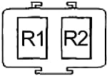
Dodge Monaco (1988 – 1992) – fuse box diagram

Dodge Monaco (1988 – 1992) – fuse box diagram

Year of production: 1988, 1989, 1990, 1991, 1992

Passenger Compartment Fuse Box

Dodge Monaco - fuse box diagram - passenger compartment
Dodge Monaco – fuse box diagram – passenger compartment
Fuse [A] Protected Component
1 3 ’91-’92: Left & Right Pods, Cluster Light, Console, Radio, Disc Player
2 10 ’88-’89: Mirrors, Chime, VM Module, Trip Computer, Radio, Heater, Heater & A/C Controls, Digital Instrument Cluster, Clock (Battery for Memory)
15 ’90: Mirrors, Chime, IOD, VM Module, Courtesy Lights, Trip Computer Radio, Decklid Release, Dome Light, Illumination Entry Module, Underhood Light, Glove Box Light, Trunk Light, VDS Module, Keyless Entry
3 ’91-’92: Trip Computer, VM Module, Climate, Control Display, Radio Disc Player
3 5 ’88-’90: Back-Up Lights
20 ’91-’92: Intermittent Wiper Module
4 5 ’88-’90: Vanity Lights
10 ’91-’92: Radio, Compact Disc
5 20 ’88-’90: Radio, Cigarette Lighter
3 ’91-’92: Lighting Control Module
6 20 ’91-’92: Chime, Clock, Keyless Entry, VM Module, Trip Computer, Power Mirrors, Underhood, Courtesy, Rear, Glove Box, Dome/Reading, Trunk, Vanity Lights, Power Door Locks, ATC Control Module, Radio, Illuminated Entry, Deck Lid Release Solenoid
7 7.5 ’88-’90: Automatic Transmission
5 ’91-’92: Chime, Clock, Instrument Cluster, Cruise Indicator, VM Module, Illuminated Entry, Trip Computer, Cruise Control Servo
8 15 ’88-’90: Trip Computer, VM Module, Clock, Chime System Illumination Entry, Rear Defogger Relay, Back-Up Lights, Transmission Computer (Ignition)
20 ’91-’92: Power Mirrors
9 15 ’88-’90: Light Control System (Ignition)
20 ’91-’92: Anti-Lock, Console, Horns, Restraint Module, Power Antenna, Diagnostic Connector
10 10 ’88-’90: Instrument Cluster, Light Outage, Module, Heater & A/C Controls, Passive Restraint Module
7.5 ’91-’92: Right Side Exterior Lights
11  –
12 20 ’88-’90: Stoplights, Turn, Hazard, Park, Side & License Lights (Left Side)
10 ’91-’92: Center Stoplight, Brake Switch
13 7.5 ’88-’89: Instrument Panel LCD
3 ’90: Instrument Panel LCD
14 7.5 ’88-’89: Instrument Panel & Clock
3 ’90: Instrument Panel & Clock
15 ’91-’92: Climate Module & Display, EGR Solenoid, Light Outage Module, Air Control Module, Daytime Running Lights, HEVAC Module
15 10 ’88-’90: Instrument Cluster
10 ’91-’92: Lamp Outage Module, Left Side, Front and Rear Exterior Lights
16 30 ’88-’90: Rear Defogger, Power Antenna
17 15 ’88-’89: Interior Lights, Glove Box Light, Trunk Light, Underhood Light
18 20 ’88-’90: Horn, Stoplight Switch
19 10 ’88-’90: Passive Restraint System
10 ’91-’92: Right Low Beam Headlight
20 20 ’88-’90: Stoplights, Turn, Hazard, Park, Side & License Lights (Right Side)
10 ’91-’92: Left Low Beam Headlight
Circuit Breaker
21 12.5 ’88-’90: Headlights
21 ’91-’92: Headlights, Daytime Running Lights
22 30 Power Seats, Power Door Locks, Passive Restraint Motors (’91-’92)
23 30 ’88-’90: Protection System Motors & Relays, Passive Restraint System (’90)
24 30 ’88-’90: Intermittent Wiper/Washer
30 ’91-’92: Power Windows
25 30 ’88-’90: Power Windows & Sun Roof

Engine Compartment Fuse Box (’91-’92)

Dodge Monaco - fuse box diagram - engine compartment
Dodge Monaco – fuse box diagram – engine compartment
Fuse [A] Protected Component
1  –
2 40 Headlights
3 20 Left Park Lamps
4 40 Ignition Switch, Starter Relay, ABS
5 40 Radiator Fan Relay
6  –
7 40 ABS Pump Motor Relay
8 20 Right Park Lamps
9 40 Blower Motor
10 30 Auto Shutdown Relay, Fuel Pump Relay, Single Board Engine Controller (SBEC), Fuel Injectors, EGR Solenoid, Direct Ignition Coil, CAM Sensor, Crank Sensor, Heated O2 Sensor, Throttle Position Sensor, Coolant Temperature Sensor, Auto Idle Speed Motor, MAP Sensor, Charge Temperature Sensor
11 7.5 Ignition, Fuel Pump Relay, Alternator, Heated O2 Sensor
12 20 ABS System Relay
Relay
R1  –
R2 A/C Compressor Clutch
R3 Fuel Pump
R4  –
R5 Starter
R6 Auto Shutdown
R7 ABS Pump Motor
R8 ABS Warning Lamp
R9 ABS System
R10 Radiator Fan

Passenger Compartment Relay Box

Dodge Monaco -fuse box diagram - passenger relay box
Dodge Monaco -fuse box diagram – passenger relay box
No. Relay
A Power Antenna
B Rear Window Defroster
C Low Beam Headlamp
D High Beam Headlamp
E  –
F Illuminated Entry
G Horn
H Cruise Control
J Parking Lamp
K  –

Engine Compartment Relay Box (’88-’90)

Dodge Monaco - fuse box diagram - engine relay box
Dodge Monaco – fuse box diagram – engine relay box
No. Relay
A Ignition
B Starter
C Radiator Fan
D A/C Compressor Clutch
E B+ Latch
F Fuel Pump
WARNING: Terminal and harness assignments for individual connectors will vary depending on vehicle equipment level, model, and market.
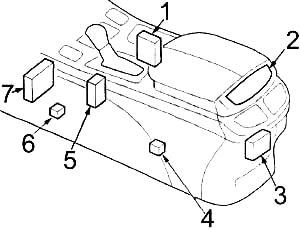
Dodge Ram 3500 (2011 – 2013) – fuse box diagram

Dodge Ram 3500 (2011 – 2013) – fuse box diagram

Year of production: 2011, 2012, 2013

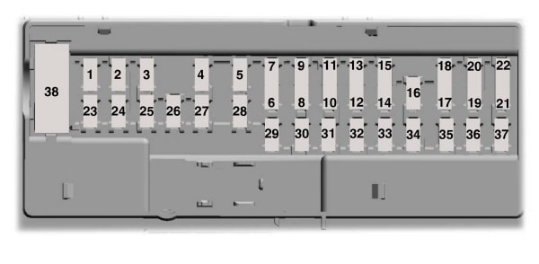
Fuse box diagram

Dodge Ram 3500 - fuse box diagram
Dodge Ram 3500 – fuse box diagram

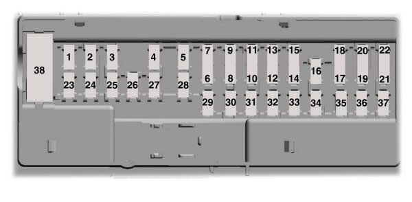
No.
A
Protected Component
1 15 Stop Lamp Switch
2 20  –
3 30 except for 6.7L: Drive Train Control Module
4  –
5 25 115V AC Inverter
6 20 Cigar Lighter (Instrument Panel) or Power Outlet (Front Console), Rain Sensor
7 20 Rear Power Outlet or Power Outlet (Center Seat)
8 20 Front Heated Seat, Steering Wheel
9 20 Rear Heated Seats
10 15 Compass Module, Hands-Free Module, Video Screen Module, Satellite Video Module, Universal Garage Door Opener Module, Vanity Lamp
11 10 A/C Heater Control, Underhood Lamp
12 30 Radio, Radio Amplifier
13 20 Cluster, Multi-Function Switch, Steering Column Module, Siren, Tire Pressure Monitoring System, Wireless Control Module
14 20 Back-Up Camera
15 20 Cluster, Multi-Function Switch, Steering Angle Sensor, Trailer Tow Module, Transfer Case Selector Switch, Inside Rearview Mirror, Fuel Heated Relay (6.7L), O2 Sensor Module, Drive Train Control Module (except 3.7L), Power Seat Module, Audio Telematics, Daytime Running Lights Relay
16 10 Occupant Restraint Controller Module (Airbag)
17  –
18 15 Center Stop Lamp
19 25 Automatic Shutdown (No.1, No.2)
20 15 Cluster, Lower Bank Switch, Upper Bank Switch, Steering Control Module Instrument
21 20 Automatic Shutdown (No.3)
22 10 Horn (Right)
23 10 Horn (Left)
24  –
25 20 Gasoline: Fuel Pump Motor
20 Diesel: Lift Pump
26 10 Driver Window/Door Lock Switch
27 10 Ignition Switch
28 15 except for 6.7L: Powertrain Control Module (PCM)
29 10 Tire Pressure Monitoring System
30 15 Diagnostic Connector
31 20 Back-Up Lamp Switch
32 10 Occupant Restraint Controller Module (Airbag)
33 10 Powertrain Control Module (PCM)
34 10 A/C Heater Control, Infrared Sensor, Park Assist Module, Radiator Fan (High) Relay (except 6.7L), Compass Module
35 15 Left Front & Rear Parklamps
36 20 Power Outlet (Front Console) or Cigar Lighter (Instrument Panel)
37 10 Stop Lamp Switch, ABS, Dynamics Sensor
38 25 Door Lock Relay, Driver Door Unlock Relay, Passenger Door Unlock Relay
J1 40 Trailer Tow
J2 30 Brake Provision Module
J3 30 Diesel: Powertrain Control Module (PCM)
J4 25 Driver Door Module
J5 25 Passenger Door Module
J6 40 ABS
J7 30 ABS
J8 40 Circuit Breaker (CB1 – Power Seat)
J9 30  –
J10 30 Sway Bar Module
J11 30 Transfer Case Module
J12 30 Rear Window Defogger
J13 60 Fuse: “10”, “11”, “12”, “13”
J14 20 Trailer Tow Lamps/Park Lamps
J15 40 Front Blower
J16  –
J17 40 Starter
J18 20 Powertrain Control Module Transmission Range
J19 60 Radiator Fan (Low) Relay, Radiator Fan (High) Relay
J20 30 Wiper On/Off Relay
J21 20 Washer Control
J22 25 Sunroof Module
Circuit Breaker
CB1 25 Power Seat
Relay
R1 Ignition (Run/Acc)
R2 Ignition (Run)
R3 Starter
R4 Run-Start
R5 Transmission Control Module (TCM)
R6 Park Lamp
R7 EBL
R8  –
R9 Blower Motor
R10 Automatic Shutdown
R11 Radiator Fan (Low)

WARNING: Terminal and harness assignments for individual connectors will vary depending on vehicle equipment level, model, and market.
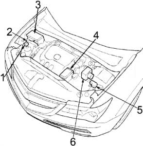
Dodge Ram 2500 (2011 – 2013) – fuse box diagram

Dodge Ram 2500 (2011 – 2013) – fuse box diagram

Year of production: 2011, 2012, 2013

Fuse box diagram

Dodge Ram 2500 - fuse box diagram
Dodge Ram 2500 – fuse box diagram

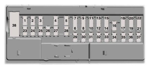
No.
A
Protected Component
1 15 Stop Lamp Switch
2 20  –
3 30 except for 6.7L: Drive Train Control Module
4  –
5 25 115V AC Inverter
6 20 Cigar Lighter (Instrument Panel) or Power Outlet (Front Console), Rain Sensor
7 20 Rear Power Outlet or Power Outlet (Center Seat)
8 20 Front Heated Seat, Steering Wheel
9 20 Rear Heated Seats
10 15 Compass Module, Hands-Free Module, Video Screen Module, Satellite Video Module, Universal Garage Door Opener Module, Vanity Lamp
11 10 A/C Heater Control, Underhood Lamp
12 30 Radio, Radio Amplifier
13 20 Cluster, Multi-Function Switch, Steering Column Module, Siren, Tire Pressure Monitoring System, Wireless Control Module
14 20 Back-Up Camera
15 20 Cluster, Multi-Function Switch, Steering Angle Sensor, Trailer Tow Module, Transfer Case Selector Switch, Inside Rearview Mirror, Fuel Heated Relay (6.7L), O2 Sensor Module, Drive Train Control Module (except 3.7L), Power Seat Module, Audio Telematics, Daytime Running Lights Relay
16 10 Occupant Restraint Controller Module (Airbag)
17  –
18 15 Center Stop Lamp
19 25 Automatic Shutdown (No.1, No.2)
20 15 Cluster, Lower Bank Switch, Upper Bank Switch, Steering Control Module Instrument
21 20 Automatic Shutdown (No.3)
22 10 Horn (Right)
23 10 Horn (Left)
24  –
25 20 Gasoline: Fuel Pump Motor
20 Diesel: Lift Pump
26 10 Driver Window/Door Lock Switch
27 10 Ignition Switch
28 15 except for 6.7L: Powertrain Control Module (PCM)
29 10 Tire Pressure Monitoring System
30 15 Diagnostic Connector
31 20 Back-Up Lamp Switch
32 10 Occupant Restraint Controller Module (Airbag)
33 10 Powertrain Control Module (PCM)
34 10 A/C Heater Control, Infrared Sensor, Park Assist Module, Radiator Fan (High) Relay (except 6.7L), Compass Module
35 15 Left Front & Rear Parklamps
36 20 Power Outlet (Front Console) or Cigar Lighter (Instrument Panel)
37 10 Stop Lamp Switch, ABS, Dynamics Sensor
38 25 Door Lock Relay, Driver Door Unlock Relay, Passenger Door Unlock Relay
J1 40 Trailer Tow
J2 30 Brake Provision Module
J3 30 Diesel: Powertrain Control Module (PCM)
J4 25 Driver Door Module
J5 25 Passenger Door Module
J6 40 ABS
J7 30 ABS
J8 40 Circuit Breaker (CB1 – Power Seat)
J9 30  –
J10 30 Sway Bar Module
J11 30 Transfer Case Module
J12 30 Rear Window Defogger
J13 60 Fuse: “10”, “11”, “12”, “13”
J14 20 Trailer Tow Lamps/Park Lamps
J15 40 Front Blower
J16  –
J17 40 Starter
J18 20 Powertrain Control Module Transmission Range
J19 60 Radiator Fan (Low) Relay, Radiator Fan (High) Relay
J20 30 Wiper On/Off Relay
J21 20 Washer Control
J22 25 Sunroof Module
Circuit Breaker
CB1 25 Power Seat
Relay
R1 Ignition (Run/Acc)
R2 Ignition (Run)
R3 Starter
R4 Run-Start
R5 Transmission Control Module (TCM)
R6 Park Lamp
R7 EBL
R8  –
R9 Blower Motor
R10 Automatic Shutdown
R11 Radiator Fan (Low)

WARNING: Terminal and harness assignments for individual connectors will vary depending on vehicle equipment level, model, and market.
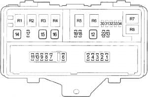
Dodge Ram 1500 (2011 – 2013) – fuse box diagram

Dodge Ram 1500 (2011 – 2013) – fuse box diagram

Year of production: 2011, 2012, 2013

Fuse box diagram

Dodge Ram 1500 - fuse box diagram
Dodge Ram 1500 – fuse box diagram

No.
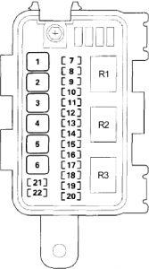
A
Protected Component
1 15 Stop Lamp Switch
2 20  –
3 30 except for 6.7L: Drive Train Control Module
4  –
5 25 115V AC Inverter
6 20 Cigar Lighter (Instrument Panel) or Power Outlet (Front Console), Rain Sensor
7 20 Rear Power Outlet or Power Outlet (Center Seat)
8 20 Front Heated Seat, Steering Wheel
9 20 Rear Heated Seats
10 15 Compass Module, Hands-Free Module, Video Screen Module, Satellite Video Module, Universal Garage Door Opener Module, Vanity Lamp
11 10 A/C Heater Control, Underhood Lamp
12 30 Radio, Radio Amplifier
13 20 Cluster, Multi-Function Switch, Steering Column Module, Siren, Tire Pressure Monitoring System, Wireless Control Module
14 20 Back-Up Camera
15 20 Cluster, Multi-Function Switch, Steering Angle Sensor, Trailer Tow Module, Transfer Case Selector Switch, Inside Rearview Mirror, Fuel Heated Relay (6.7L), O2 Sensor Module, Drive Train Control Module (except 3.7L), Power Seat Module, Audio Telematics, Daytime Running Lights Relay
16 10 Occupant Restraint Controller Module (Airbag)
17  –
18 15 Center Stop Lamp
19 25 Automatic Shutdown (No.1, No.2)
20 15 Cluster, Lower Bank Switch, Upper Bank Switch, Steering Control Module Instrument
21 20 Automatic Shutdown (No.3)
22 10 Horn (Right)
23 10 Horn (Left)
24  –
25 20 Gasoline: Fuel Pump Motor
20 Diesel: Lift Pump
26 10 Driver Window/Door Lock Switch
27 10 Ignition Switch
28 15 except for 6.7L: Powertrain Control Module (PCM)
29 10 Tire Pressure Monitoring System
30 15 Diagnostic Connector
31 20 Back-Up Lamp Switch
32 10 Occupant Restraint Controller Module (Airbag)
33 10 Powertrain Control Module (PCM)
34 10 A/C Heater Control, Infrared Sensor, Park Assist Module, Radiator Fan (High) Relay (except 6.7L), Compass Module
35 15 Left Front & Rear Parklamps
36 20 Power Outlet (Front Console) or Cigar Lighter (Instrument Panel)
37 10 Stop Lamp Switch, ABS, Dynamics Sensor
38 25 Door Lock Relay, Driver Door Unlock Relay, Passenger Door Unlock Relay
J1 40 Trailer Tow
J2 30 Brake Provision Module
J3 30 Diesel: Powertrain Control Module (PCM)
J4 25 Driver Door Module
J5 25 Passenger Door Module
J6 40 ABS
J7 30 ABS
J8 40 Circuit Breaker (CB1 – Power Seat)
J9 30  –
J10 30 Sway Bar Module
J11 30 Transfer Case Module
J12 30 Rear Window Defogger
J13 60 Fuse: “10”, “11”, “12”, “13”
J14 20 Trailer Tow Lamps/Park Lamps
J15 40 Front Blower
J16  –
J17 40 Starter
J18 20 Powertrain Control Module Transmission Range
J19 60 Radiator Fan (Low) Relay, Radiator Fan (High) Relay
J20 30 Wiper On/Off Relay
J21 20 Washer Control
J22 25 Sunroof Module
Circuit Breaker
CB1 25 Power Seat
Relay
R1 Ignition (Run/Acc)
R2 Ignition (Run)
R3 Starter
R4 Run-Start
R5 Transmission Control Module (TCM)
R6 Park Lamp
R7 EBL
R8  –
R9 Blower Motor
R10 Automatic Shutdown
R11 Radiator Fan (Low)

WARNING: Terminal and harness assignments for individual connectors will vary depending on vehicle equipment level, model, and market.