Ford F-150 (2019 – 2020) – fuse box diagram
Year of production: 2019, 2020
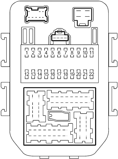
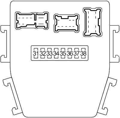
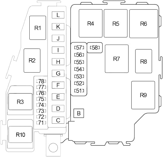
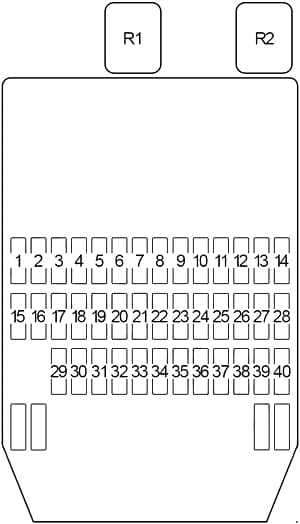
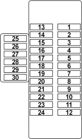
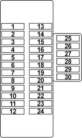
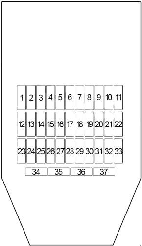
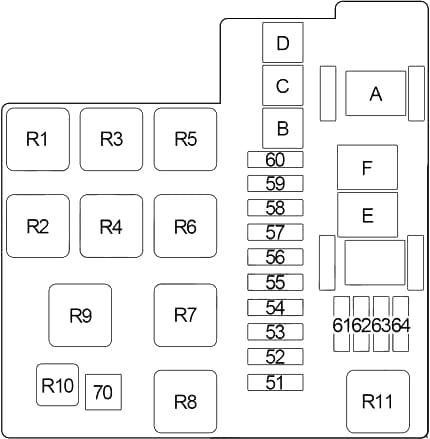
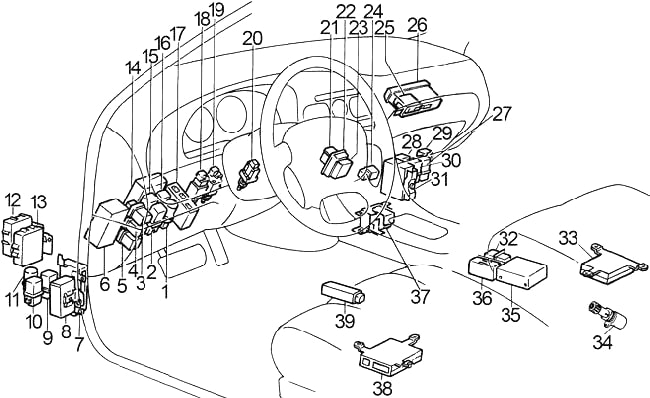
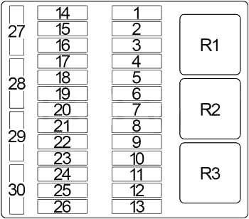
Passenger Compartment Fuse Box
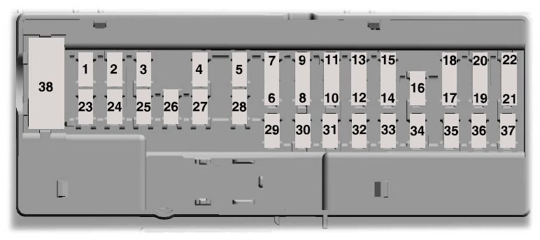
Ford F-150 – fuse box diagram passenger compartment
| Fuse Number | Fuse Rating | Protected Component |
| 1 | – | Not used. |
| 2 | 7.5A | Memory module logic.
Memory seat switches. Lumbar motor. |
| 3 | 20A | Driver door lock motor. |
| 4 | 5A | Trailer brake control. |
| 5 | 20A | Not used (spare). |
| 6 | 10A | Not used (spare). |
| 7 | 10A | Not used (spare). |
| 8 | 10A | Not used (spare). |
| 9 | 10A | Extended power module (base). |
| 10 | 5A | Embedded modem module. |
| 11 | 5A | Combined sensor module. |
| 12 | 7.5A | Climate head module.
Smart datalink connector. |
| 13 | 7.5A | Cluster.
Steering column control module. |
| 14 | 10A | Brake on/off switch. |
| 15 | 10A | Smart datalink connector. |
| 16 | 15A | Tailgate release. |
| 17 | 5A | Heads up display.
Terrain switch. Ignition switch and passive-entry passivestart start stop switch. |
| 18 | 5A | Key inhibit solenoid. |
| 19 | 7.5A | Extended power module (base). |
| 7.5A | Restraint control module (Raptor). | |
| 20 | 7.5A | Not used (spare). |
| 21 | 5A | Heads up display.
In car temperature with humidity sensor. |
| 22 | 5A | Passenger occupant detection (Raptor). |
| 23 | 10A | Power driven rear glass switch.
Inverter. Driver side window. Moonroof. Vista roof. |
| 24 | 20A | Central lock/unlock. |
| 25 | 30A | Driver door control module. |
| 26 | 30A | Passenger door control module. |
| 27 | 30A | Vista roof.
Moonroof. |
| 28 | 20A | Not used (spare). |
| 29 | 30A | Not used (spare). |
| 30 | 30A | Not used (spare). |
| 31 | 15A | Adjustable pedal switch and motor. |
| 32 | 10A | Multi-function display.
SYNC. Radio frequency receiver. |
| 33 | 20A | Radio. |
| 34 | 30A | Run-start relay. |
| 35 | 5A | Selectable drive mode switch.
Upfitter switches (Raptor). |
| 36 | 15A | 360 camera module.
Heated steering wheel module. Rear-view mirror. Rear heated seats. Lane departure warning module. Automatic high beam module. Image processing module A. |
| 37 | 20A | Not used (spare). |
| 38 | 30A | Circuit breaker. Rear window switches and motors. |
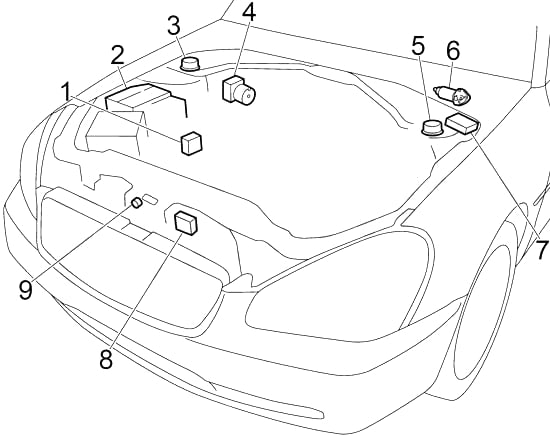
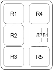
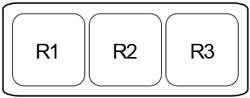
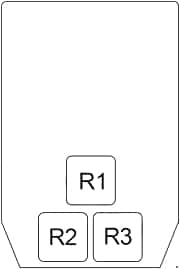
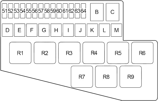
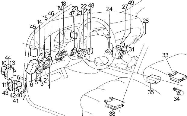
Engine compartment fuse box (2019-2020 (model year))
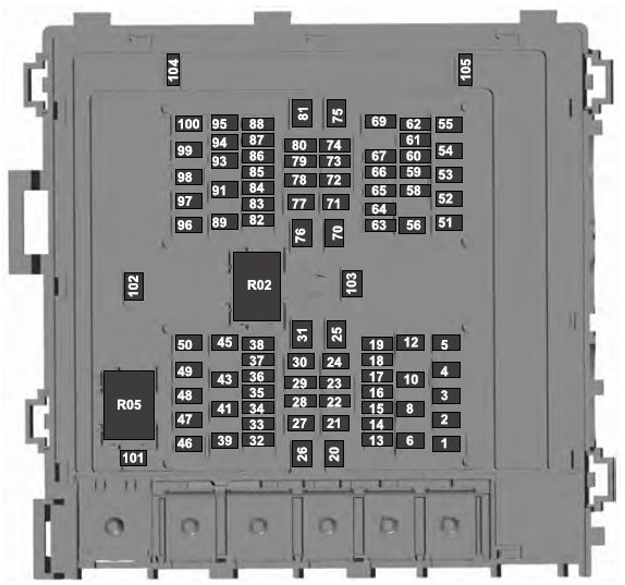
Ford F-150 – fuse box diagram – engine compartment
| Fuse number | Fuse rating | Protected component |
| 1 | 25A1 | Horn. |
| 2 | 50A2 | Electric fan 1. |
| 3 | 30A2 | Windshield wiper motor. |
| 4 | 60A2 | Body control module. |
| 5 | 30A2 | Starter relay. |
| 6 | 20A2 | Power point 1. |
| 8 | 20A2 | Power point 2. |
| 10 | 5A1 | Rain sensor. |
| 12 | 15A2 | Upfitter 1 relay (Raptor). |
| 13 | 10A1 | 4×4 run/start. 13 1 Adaptive cruise control run/start module. |
| 14 | – | Not used (base). |
| 15A1 | Not used (spare) (Raptor). | |
| 15 | 7.5A1 | Front view camera. 15 1 Voltage quality module. |
| 15A1 | Voltage quality module (Raptor). | |
| 16 | 10A1 | Powertrain control module. Transmission control module run/start. |
| 17 | 10A1 | Anti-lock brakes run/start. |
| 18 | 10A1 | Electric power steering run/start. |
| 19 | 5A1 | Upfitter 5 relay (Raptor). |
| 20 | 40A2 | Blower motor. |
| 21 | 30A2 | Passenger seat motors. |
| 22 | 20A1 | Radio amplifier. |
| 23 | 10A1 | Alt A sensor. |
| 24 | 30A2 | Trailer brake control module. |
| 25 | 50A2 | Body control module 1. |
| 26 | 50A2 | Electric fan (Gas). |
| 27 | 30A2 | Driver seat motors/memory module. |
| 28 | 15A1 | Heated seat. |
| 29 | 10A1 | 4×4 solenoid. |
| 30 | 25A2 | Trailer tow battery charge. |
| 31 | – | Not used. |
| 32 | 10A1 | A/C clutch. |
| 33 | – | Not used. |
| 34 | 10A1 | Vehicle power 5 (Diesel). |
| 35 | 20A1 | Vehicle power 4 (Gas). |
| 15A1 | Vehicle power 4 (Diesel). | |
| 36 | 10A1 | Vehicle power 3. |
| 37 | 25A1 | Vehicle power 2 (Gas). |
| 15A1 | Vehicle power 2 (Diesel). | |
| 38 | 25A1 | Vehicle power 1 (Gas). |
| 20A1 | Vehicle power 1 (Diesel). | |
| 39 | – | Not used. |
| 41 | 30A2 | Body control module voltage quality module feed. |
| 43 | 20A2 | Trailer tow lamps module. |
| 45 | – | Not used. |
| 46 | 10A1 | Steering column lock. |
| 47 | 50A2 | Powertrain control heater 3 (Diesel). |
| 48 | 30A2 | Fuel filter heater (Diesel). |
| 49 | – | Not used. |
| 50 | 30A2 | Fuel pump. |
| 51 | 20A2 | Power point 3. |
| 52 | 50A2 | Powertrain control heater 2 (Diesel). |
| 53 | 25A2 | Trailer tow park lamps. |
| 54 | – | Not used. |
| 55 | 15A2 | Upfitter 2 relay (Raptor). |
| 56 | – | Not used. |
| 58 | 5A1 | USB smart charger. |
| 59 | – | Not used. |
| 60 | – | Not used. |
| 61 | – | Not used (base). |
| 15A1 | Not used (spare) (Raptor). | |
| 62 | 5A1 | Upfitter 6 relay (Raptor). |
| 63 | 25A1 | 4×4. |
| 64 | 15A1 | E-locker. |
| 65 | – | Not used. |
| 66 | – | Not used. |
| 67 | – | Not used. |
| 69 | – | Not used. |
| 70 | 40A2 | Anti-lock brake system (ABS) valves. Electric parking brake. |
| 71 | 25A2 | 4×4. |
| 72 | – | Not used. |
| 73 | – | Not used. |
| 74 | 10A1 | Trailer tow backup lamps. |
| 75 | – | Not used. |
| 76 | 40A2 | Body control module 2. |
| 77 | 30A2 | Climate controlled seat. |
| 78 | 10A1 | Spot light module. |
| 79 | – | Not used. |
| 80 | 10A1 | Heated windshield wiper.
Upfitter 4 relay (Raptor). |
| 81 | – | Not used. |
| 82 | 30A1 | Transmission fluid pump. |
| 5A1 | Powertrain control module (Diesel). | |
| 83 | 15A1 | Transmission control module. |
| 84 | – | Not used. |
| 85 | – | Not used. |
| 86 | – | Not used. |
| 87 | – | Not used. |
| 88 | 10A1 | Multi-contour seats relay. Upfitter 3 relay (Raptor). |
| 89 | 30A2 | Power running boards. |
| 91 | – | Not used. |
| 93 | 15A1 | Heated mirrors. |
| 94 | 15A1 | Rear heated seat module (Raptor, Diesel). |
| 95 | – | Not used (base). |
| 15A1 | Not used (spare) (Raptor). | |
| 96 | – | Not used. |
| 97 | 40A2 | Electric fan (Raptor). |
| 50A2 | Powertrain control heater 1 (Diesel). | |
| 98 | 15A2 | 10R transmission module r/s. 98 2 3.3L transmission fluid pump. |
| 99 | 40A2 | Heated rear window. |
| 100 | 25A2 | Diesel exhaust fluid (DEF) heater relay (Diesel). |
| 101 | 25A2 | Electric fan (base). |
| 102 | 30A2 | Power sliding back window. |
| 103 | 20A2 | Trailer tow stop-turn relay fuse. |
| 104 | 15A1 | Snowplow switch. Rear heated seats (base). |
| 105 | 10A1 | Telescoping mirror. |
1 Micro 2 fuse.
2 Slotted M case fuse.
Note: Spare fuse amperage may vary.
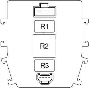
| Relay Number | Fuse Rating | Protected Component |
| R02 | – | Powertrain control module relay. |
| R05 | – | Electric fan relay. |