Infiniti G20 (1998 – 2002) – fuse box diagram
Year of production: 1998, 1999, 2000, 2001, 2002
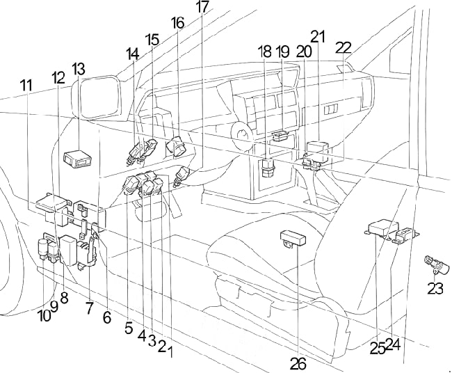
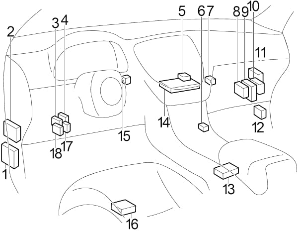
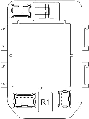
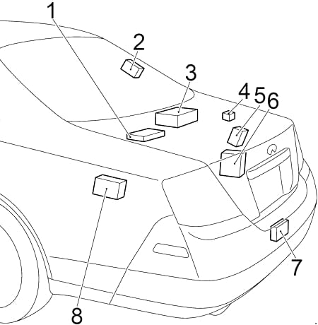
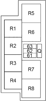
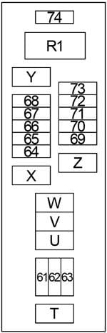
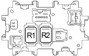
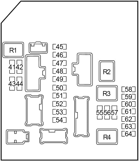
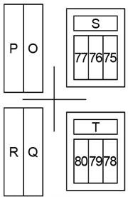
Passenger Compartment
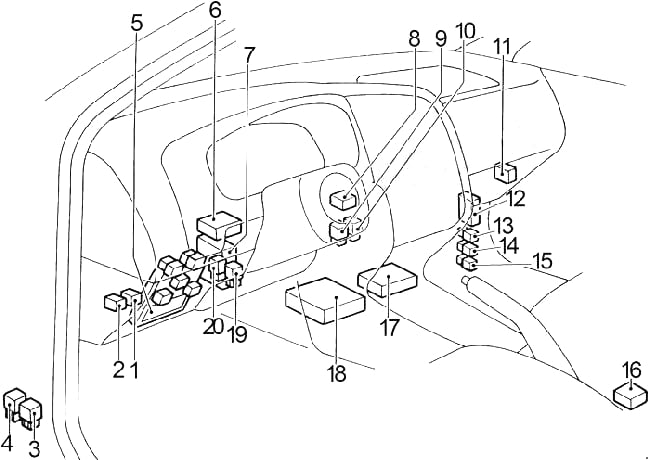
- Circuit Breaker No.1 (Power Window Relay, Door Lock, Interior Lamp, Sunroof)
- Circuit Breaker No.2 (Power Seat)
- Door Mirror Defogger Relay
- Fuel Pump Relay No.2
- Fuse Box
- Automatic Speed Control Device (ASCD) Control Unit
- Smart Entrance Control Unit
- ’00-’02: Infiniti Vehicle Immobilizer System
- Engine Control Module (ECM) Relay
- Fuel Pump Relay No.1
- Daytime Light Control Unit
- ’98-’99: ABS Control Unit
’00-’02: Headlamp Battery Saver Control Unit - ’00-’02: Headlamp RH Relay
- ’00-’02: Tail Lamp Relay
- ’00-’02: Headlamp LH Relay
- Air Bag Diagnosis Sensor Unit
- Transmission Control Module (TCM)
- Engine Control Module (ECM)
- ’98-’99: Automatic Speed Control Device (ASCD) Brake Hold Relay
’00-’02: Trunk Lid Opener Relay - Combination Flasher Unit
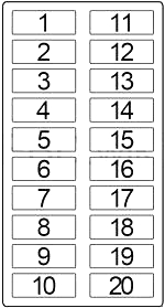
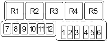
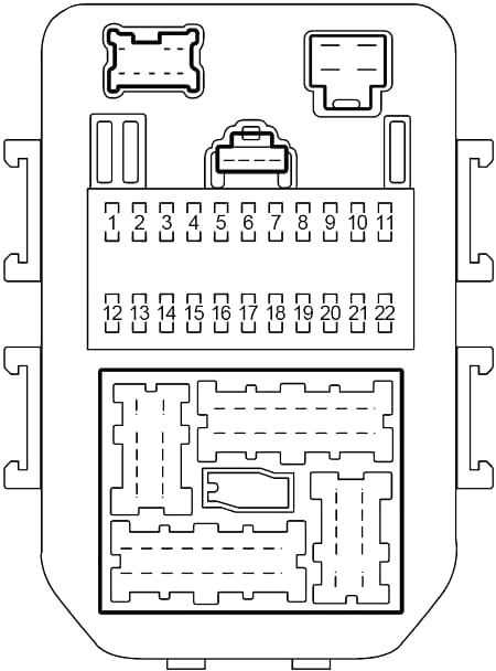
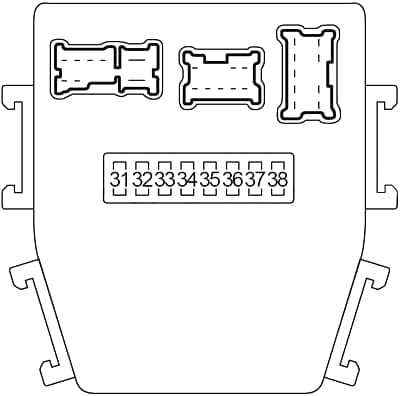
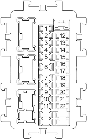
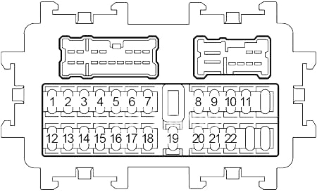
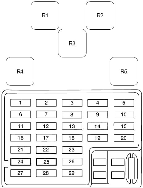
Passenger Compartment Fuse Box
| No. |
A |
Circuit Protected |
| 1 | 15 | Blower Motor |
| 2 | 15 | Blower Motor |
| 3 | 7.5 | ABS |
| 4 | 7.5 | Infiniti Vehicle Immobilizer System |
| 5 | 7.5 | Combination Meter, Sucurity Indicator, Infiniti Vehicle Immobilizer System |
| 6 | 10 | Air Conditioner |
| 7 | 10 | Canister Vent Valve Solenoid, Vacuum Cut Valve Bypass Valve |
| 8 | 10 | Smart Entrance Control Unit (Door Lock, Front Door Switch, Interior Lamp), Headlamp Battery Saver Control Unit, Warning Chime, Rear Window Defogger Relay, Door Mirror Defogger Relay, Power Window Relay (Power Window, Sunroof), Automatic Speed Control Device (ASCD) Clutch Switch (Manual Transmission), ASCD Brake Switch, ASCD Control Unit, Infiniti Vehicle Immobilizer System |
| 9 | 10 | Door Mirror Defogger Relay, Door Mirror Remote Control Switch |
| 10 | 7.5 | Audio, Power Antenna, Smart Entrance Control Unit |
| 11 | 10 | Combination Meter, Generator, Back-Up Lamp (Back-Up Lamp Switch (Manual Transmission), Park/Neutral Position Switch (Automatic Transmission)) |
| 12 | 7.5 | Hazard Switch, Combination Flasher Unit |
| 13 | 15 | Cigarette Lighter |
| 14 | 15 | Stop Lamp Switch, Stop Lamps, Automatic Speed Control Device (ASCD) Control Unit |
| 15 | 15 | Trunk Lid Opener Relay |
| 16 | 10 | Headlamp Battery Saver Control Unit, Park/Neutral Position Relay, Park/Neutral Position Switch, Cooling Fan, Theft Warning Relay |
| 17 | 15 | Fuel Pump Relay |
| 18 | 10 | Heated Oxygen Sensors |
| 19 | 20 | Front Wiper Motor, Front Washer Motor, Front Wiper Switch |
| 20 | 10 | Hazard Switch, Combination Flasher Unit, Multi-Remote Control Relay |
| 21 | 10 | Transmission Control Module (TCM) |
| 22 | 10 | Air Bag Diagnosis Sensor Unit |
| 23 | – | – |
| 24 | 10 | Smart Entrance Control Unit (Door Lock, Front Door Switch, Interior Lamp), Headlamp Battery Saver Control Unit, Vanity Mirror Lamps, Trunk Room Lamp, Key Switch, Warning Chime, Audio, Power Antenna, Power Window Relay (Power Window, Sunroof), Homelink Transmitter |
| 25 | 10 | Fuel Injectors |
| 26 | 10 | Starting System, Daytime Light Control Unit |
| 27 | – | – |
| 28 | 10 | Heated Seat |
| 29 | – | – |
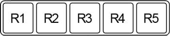
| Relay | ||
| R1 | Multi-Remote Control | |
| R2 | Power Window | |
| R3 | Blower | |
| R4 | Ignition | |
| R5 | Accessory | |
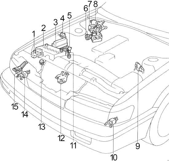
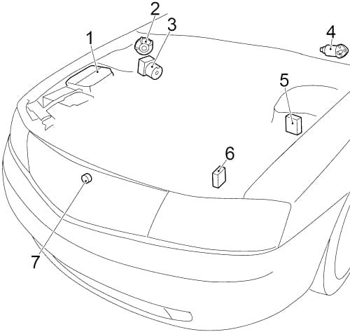
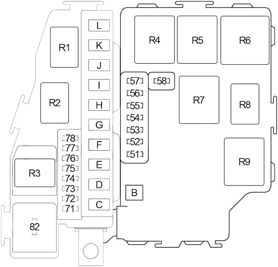
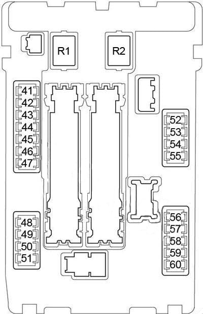
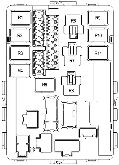
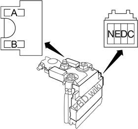
Engine Compartment
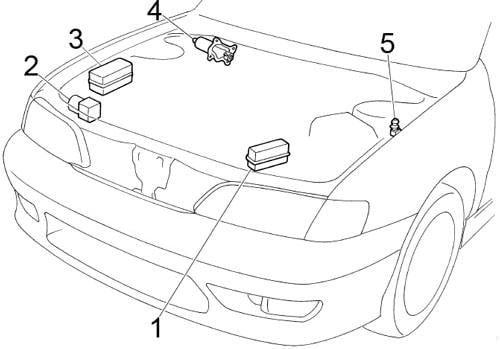
- Fuse Box
- ABS Actuator and Electric Unit
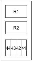
- Relay Box
- Front Wiper Motor
- Hood Switch
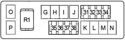
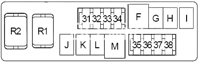
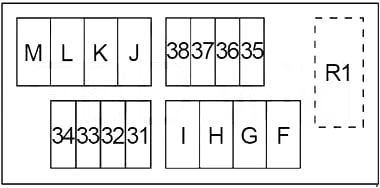
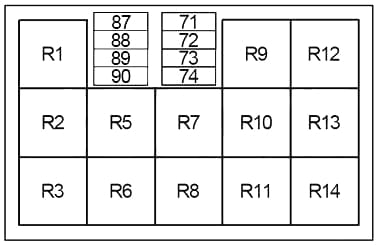
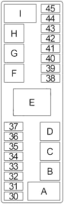
Engine Compartment Fuse Box
| No. |
A |
Circuit Protected |
| 30 | – | – |
| 31 | – | – |
| 32 | 15 | ’00-’02: Headlamp LH Relay (Headlamp LH, High Beam Indicator, Headlamp Battery Saver Control Unit, Theft Warning Lamp Relay) |
| 15 | ’98-’99: Headlamp LH, Daytime Light Control Unit, Theft Warning Lamp Relay | |
| 33 | 15 | ’00-’02: Headlamp RH Relay (Headlamp RH, Front Fog Lamp Relay, Headlamp Battery Saver Control Unit, Theft Warning Lamp Relay) |
| 15 | ’98-’99: Headlamp RH, Daytime Light Control Unit, Front Fog Lamp Relay, Theft Warning Lamp Relay | |
| 34 | 10 | ’00-’02: Tail Lamp Relay (Side Marker Lamps, License Lamps, Combination Lamps, Lighting Switch, Glove Box Lamp, Illumination Control Switch, Headlamp Battery Saver Control Unit, Seat Belt Buckle Switch, Warning Chime, Illumination: (Combination Meter, A/C Auto Amplifier, Push Control Unit, Audio, A/T Device, Hazard Switch, Power Window Main Switch, Rear Window Defogger Switch, Ashtray)) |
| 10 | ’98-’99: Side Marker Lamps, License Lamps, Combination Lamps, Illumination: (Combination Meter, A/C Auto Amplifier, Push Control Unit, Audio, A/T Device, Hazard Switch, Power Window Main Switch, Rear Window Defogger Switch, Ashtray, Automatic Speed Control Device (ASCD) Main Switch) | |
| 35 | 15 | Ignition Coils, Mass Air Flow Sensor, Camshaft Position Sensor |
| 36 | 10 | ’00-’02: Horn Relay (Low), Horn Switch, Automatic Speed Control Device (ASCD) Steering Switch |
| 10 | ’98-’99: Horn Low Relay, Horn Switch, Automatic Speed Control Device (ASCD) Steering Switch | |
| 37 | 7.5 | Generator |
| 38 | 15 | BOSE Speaker Amplifier |
| 39 | 20 | Rear Window Defogger Relay, Rear Window Defogger Indicator |
| 40 | 20 | Rear Window Defogger Relay |
| 41 | 10 | ’00-’02: Horn Relay (High) |
| 10 | ’98-’99: Horn High Relay, Horn Switch, Automatic Speed Control Device (ASCD) Steering Switch | |
| 42 | 15 | Fuel Pump Relay |
| 43 | 15 | Front Fog Lamp Relay |
| 44 | – | – |
| 45 | – | – |
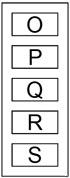
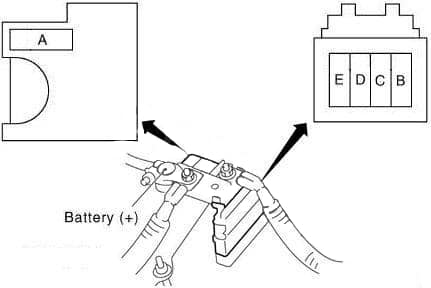
| A | 80 | Accessory Relay (Fuse: “9”, “13”, “19”), Ignition Relay (Fuse: “3”, “7”, “8”, “11”, “12”, “18”, “28”), Blower Relay (Fuse: “1”, “2”), Fuse: “4”, “5”, “14”, “15”, “20”, “24” |
| B | 40 | Cooling Fan |
| C | 40 | ’98-’01; ’02 A/T: Cooling Fan |
| 30 | ’02 M/T: Cooling Fan | |
| D | 30 | Circuit Breaker No.1 (Power Window Relay, Sunroof, Smart Entrance Control Unit (Door Lock, Front Door Switch, Interior Lamp)), Circuit Breaker No.2 (Power Seat) |
| E | 100 | Generator, Fuse: “A”, “B”, “C”, “D”, “F”, “G”, “H”, “32”, “33”, “34”, “35”, “36”, “37”, “38”, “39”, “40”, “41”, “42”, “43” |
| F | 40 | ABS |
| G | 40 | Ignition Switch |
| H | 40 | ABS |
| I | – | – |
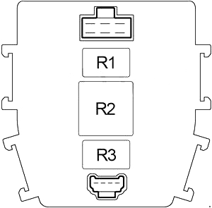
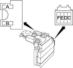
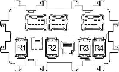
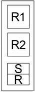
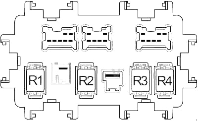
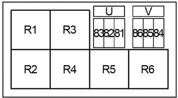
Engine Compartment Relay Box
| No. |
Circuit Protected |
| R1 | ’98-’99: Theft Warning |
| R2 | Cooling Fan (No.2) |
| R3 | ’00-’02: Theft Warning Lamp |
| ’98-’99: ABS Motor | |
| R4 | ’00-’02: Rear Window Defogger |
| ’98-’99: ABS Solenoid Valve | |
| R5 | Automatic Transmission: Park/Neutral Position |
| Manual Transmission: Clutch Interlock | |
| R6 | Air Conditioner |
| R7 | Cooling Fan (No.1) |
| R8 | ’98-’99: Horn (Low) |
| R9 | ’00-’02: Front Fog Lamp |
| ’98-’99: Theft Warning Lamp | |
| R10 | ’00-’02: Horn (Low/High) |
| ’98-’99: Horn (High) | |
| R11 | Cooling Fan (No.3) |
| R12 | ’98-’99: Front Fog Lamp |
WARNING: Terminal and harness assignments for individual connectors will vary depending on vehicle equipment level, model, and market.