Infiniti QX56 (2010 – 2017) – fuse box diagram
Year of production: 2010, 2011, 2012, 2013, 2014, 2015, 2016, 2017
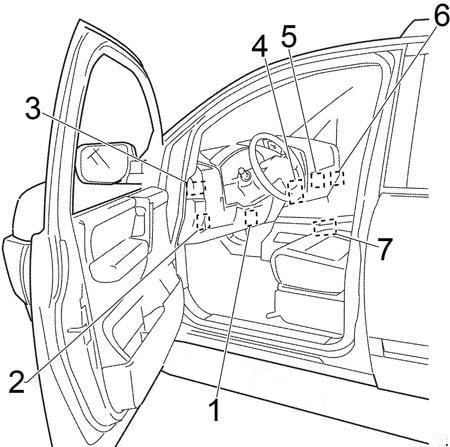
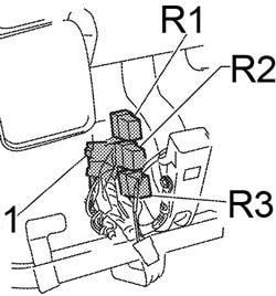
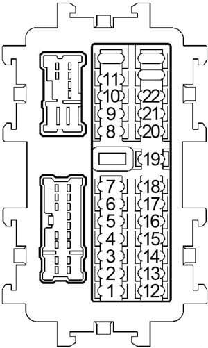
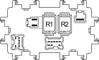
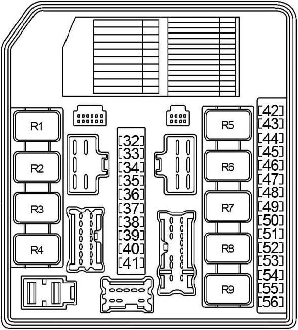
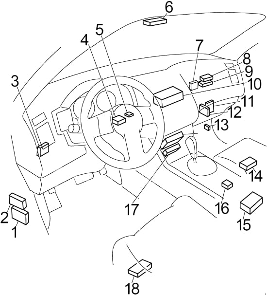
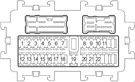
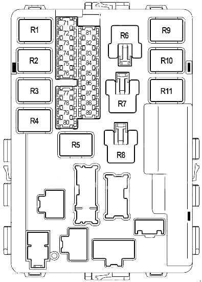
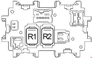
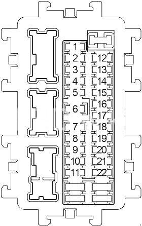
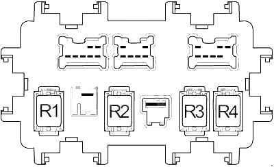
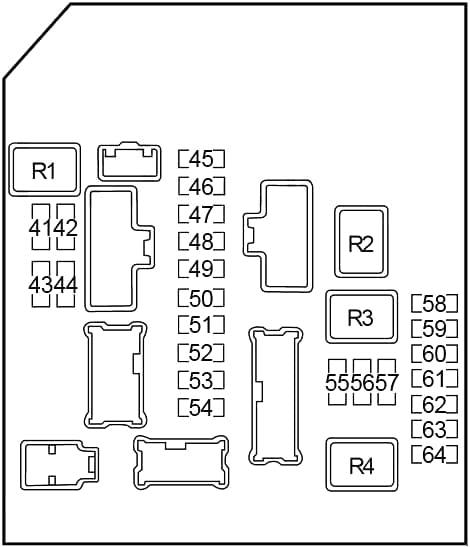
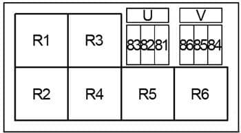
Passenger Compartment Fuse Box

| No. |
A |
Circuit Protected |
| 1 | 10 | Combination Switch |
| 2 | 10 | Air Bag Diagnosis Sensor Unit, Occupant Classification System Control Unit |
| 3 | 10 | Intelligent Cruise Control (ICC) Brake Switch, Automatic Speed Control Device (ASCD) Brake Switch, Stop Lamp Switch, Headlamp Aiming Motor LH/RH, Data Link Connector, Steering Angle Sensor, Combination Meter, Heated Steering Wheel Switch, Low Tire, Pressure Warning Control Unit, Power Steering Control Unit, CAN Gateway, Triple Switch (APS Switch), Adaptive Front Lighting System (AFS) Control Unit, AC 120V Outlet Main Switch, Climate Controlled Seat Relay |
| 4 | 10 | Rear A/C Control, Around View Monitor Control Unit, A/C Auto Amplifier, Ionizer, AV Control Unit, Rear A/C Relay, Exhaust Gas / Outside Door Detecting Sensor, Automatic Back Door Control Module, Auto Anti-Dazzling Inside Mirror, Sonar Control Unit (’14-’17), Telematics Control Module (TCU (’14-’17)) |
| 5 | 15 | BOSE Amplifier |
| 6 | 10 | Data Link Connector, Clock, Second Seat Power Unlock Switch LH/RH, Intelligent Key Warning Buzzer, Pre-crash Seat Belt Control Unit, Lights Rain Sensor, Auto Anti-dazzling Inside Mirror, Combination Meter (’14-’17) |
| 7 | 10 | Stop Lamp Switch, Body Control Module (BCM), Intelligent Cruise Control (ICC) Brake Hold Relay, Electric Brake |
| 8 | 15 | BOSE Amplifier |
| 9 | 10 | Around View Monitor Control Unit, A/C Auto Amplifier, Automatic Back Door Control Module, Reclining Switch LH/RH, Fold Down Switch LH/RH, Automatic Back Door Warning Buzzer |
| 10 | 10 | Push-Button Ignition Switch, Seat memory Switch, Body Control Module (BCM) |
| 11 | 10 | Combination Meter (’10-’13), CAN Gateway |
| 12 | 20 | Accessory Relay No.2 |
| 13 | 10 | 4WD Switch, Snow Mode / Tow Mode / VDC off Switch Assembly |
| 14 | 15 | Second Heated Seat Switch LH/RH |
| 15 | 15 | Front Heated Seat Switch LH/RH |
| 16 | 20 | Rear Blower Relay |
| 17 | – | – |
| 18 | 20 | ’10-’13: Console Power Socket |
| 19 | 10 | Door Mirror Remote Control Switch (’10-’13), Sonar Control Unit (’10-’13), Around View Monitor Control Unit, A/C Auto Amplifier, Multifunction Switch, AV Control Unit, Front Display Unit, Video Distributor, Power Window Main Switch (’14-’17), BOSE Amplifier (’14-’17), Telematics Control Module (TCU (’14-’17)), Telematics Switch (’14-’17) |
| 20 | 20 | Front Power Socket, Luggage Room Power Socket, Accessory Relay No.2 |
| 21 | 15 | Front Blower Motor |
| 22 | 15 | Front Blower Motor |

| No. |
Relay |
| R1 | Ignition |
| R2 | Ignition No.2 |
| R3 | Accessory |
| R4 | Blower |
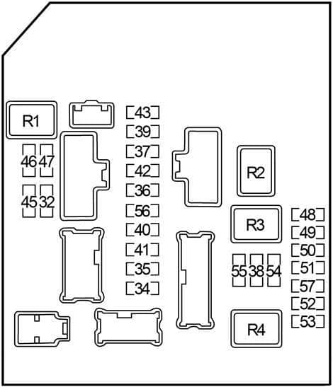
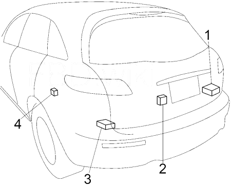
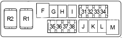
Engine Compartment Fuse Box No.1
| No. |
A |
Circuit Protected |
|
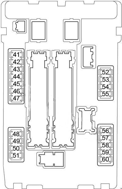
| 41 | 15 | Rear Window Defogger Relay | |
| 42 | 15 | Rear Window Defogger Relay | |
| 43 | 20 | Engine Control Module (ECM), NATS Antenna Amplifier, ECM Relay (Mass Air Flow Sensor, Evap Canister Purge Volume Control Solenoid Valve, Variable Valve Event and Lift (VVEL) Control Module, Intake Valve Timing Control Solenoid Valve, Air Fuel Ratio (A/F) Sensor, Heated Oxygen Sensor, Fuel Return Valve, EVAP Canister Vent Control Valve, Injector Relay (’14-’17)) | |
| 44 | 10 | Steering Lock Relay | |
| 45 | 30 | Front Wiper Relay | |
| 46 | 10 | Trailer Tail Lamp Relay, Rear Combination Lamp LH, Tail Lamp RH/LH, License Plate Lamp | |
| 47 | 10 | Glove Box Lamp, Climate Controlled Seat Switch, Rear A/C Control, Around View Monitor Control Unit, Heated Steering Wheel Switch, 4WD Switch Assembly, A/T Shift Selector, Multifunction Switch, Front Heated Seat Switch< Second Heated Seat Switch LH/RH, Clock, Second Seat Power Unlock Switch LH/RH, Electric Brake, AC 120V Outlet Main Switch, Console Power Socket (Cup Holder), Snow Mode / Tow Mode / Vdc Off Switch Assembly, Headlamp Aiming Switch, Door Mirror Remote Control Switch, Combination Switch (Spiral Cable), Hazard Switch, Trip Reset and Illumination Control Switch, Trip Computer Switch, Automatic Back Door Main Switch, Triple Switch, Twin Switch, Rear Combination Lamp RH, Mood Lamp Front Door Grip, Mood Lamp Rear Door Grip, Map Lamp, Telematics Sswitch | |
| 48 | – | – | |
| 49 | 10 | A/C Relay | |
| 50 | 15 | Front Fog Lamp | |
| 51 | 10 | Right Headlamp (High Beam) | |
| 52 | 10 | Left Headlamp (High Beam) | |
| 53 | 15 | Left Headlamp (Low Beam) | |
| 54 | 15 | Right Headlamp (Low Beam) | |
| 55 | 10 | Back-Up Lamp Relay, Trailer Power Relay, Transmission Control Module (TCM) | |
| 56 | 10 | Transfer Control Unit | |
| 57 | 10 | ABS, Stop Lamp Relay, Yaw Rate / Side / Decel G Sensor | |
| 58 | – | – | |
| 59 | – | – | |
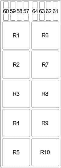
| 60 | 15 | ’10-’13: Injector Relay | |
| 61 | 15 | Ignition Coils, Condenser | |
| 62 | 10 | Engine Control Module (ECM) | |
| 63 | – | – | |
| 64 | 20 | Throttle Control Motor Relay | |
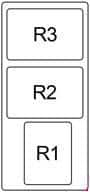
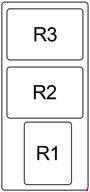
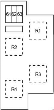
| Relay | |||
| R1 | Rear Window Defogger | ||
| R2 | Ignition No.3 | ||
| R3 | Ignition No.2 | ||
| R4 | Ignition | ||
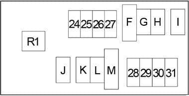
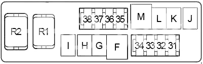
Engine Compartment Fuse Box No. 2
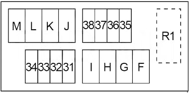
| No. |
A |
Circuit Protected |
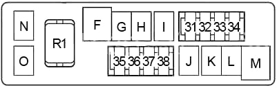
| 31 | 15 | Horn Relay |
| 32 | 10 | Alternator |
| 33 | 10 | Accelerator Pedal Actuator |
| 34 | 10 | Transfer Control Unit |
| 35 | 15 | AV Control Unit, Front Display Unit, Video Distributor, Headrest Display Unit LH/RH, Telematics Control Module (TCU (’14-’17)) |
| 36 | 10 | Vehicle Security Horn Relay |
| 37 | 10 | IPDM (Ignition Relay No.2 (Air Levelizer Control Module), Ignition Relay No.3 (Warning Buzzer, Twin Switch (Warning Systems Switch), Intelligent Cruise Control (ICC) Brake Hold Relay, Intelligent Cruise Control (ICC) Sensor, Accelerator Pedal Actuator, Advanced Driver Assistance Systems (ADAS) Control Unit, Side Radar LH/RH, Lane Camera Unit) |
| 38 | 10 | Transmission Control Module (TCM) |
| F | 40 | Electric Brake, Fuse: “T”, “V”, “79”, “84”, “85”, “86” |
| G | 40 | Ignition Relay No.1 (Fuse: “1”, “2”, “3”, “4”, “16”), Fuse: “12”, “81”, “82”, “83”, “U” |
| H | 40 | IPDM |
| I | 30 | Air Compressor Relay |
| J | 30 | Transfer Control Unit |
| K | 50 | Body Control Module (BCM), Circuit Breaker (Automatic Drive Positioner Control Unit, Driver Seat Control Unit, Lumbar Support Switch) |
| L | 30 | ABS |
| M | 50 | ABS |
| Relay |
||
| R1 | Horn | |
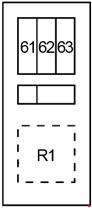
Engine Compartment Additional Fuse Holders
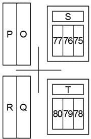
| No. |
A |
Circuit Protected |
| P | 50 | Ignition Relay (Fuse: “71”, “72”, “73”, “74”) |
| O | 50 | Variable Valve Event and Lift (VVEL) Actuator Motor Relay |
| R | 50 | Fuse: “T”, “79” |
| Q | 50 | ’10-’13: Fuse: “S”, “75”, “76”, “77” |
| 50 | ’14-’17: Fuse: “S”, “75”, “76”, “77”, “87”, “88”, “89”, “90” | |
| 75 | 15 | Wiper Deicer Relay |
| 76 | 10 | Heated Steering Wheel Relay |
| 77 | 30 | Pre-Crash Seat Belt Control Unit |
| S | 30 | Second Row Seats (Power Unlock Relay LH/RH, Up Relay 2 LH/RH, Down Relay 2 LH/RH) |
| 78 | – | – |
| 79 | 30 | Inverter Unit |
| 80 | 10 | Wiper Deicer Relay, Door Mirror |
| T | 30 | Automatic Back Door Control Module |
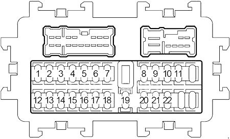
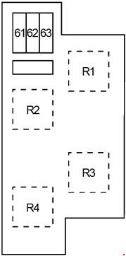
Engine Compartment Relay Box No.1
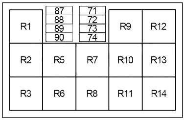
| No. |
A |
Circuit Protected |
| 71 | 30 | Engine Control Module (ECM) |
| 72 | 10 | Electrically Controlled Cooling Fan Coupling |
| 73 | 15 | Fuel Pump Control Module |
| 74 | 10 | ABS |
| 87 | 15 | ’14-’17: Injector Relay |
| 88 | 10 | ’14-’17: Daytime Running Light Relay |
| 89 | 10 | ’14-’17: Daytime Running Light Relay |
| 90 | 10 | ’14-’17: Daytime Running Light Relay |
| Relay | ||
| R1 | Remote Engine Start | |
| R2 | – | |
| R3 | ’10-’13: Vehicle Security Horn | |
| ’14-’17: Daytime Running Light | ||
| R4 | – | |
| R5 | – | |
| R6 | Back-Up Lamp | |
| R7 | Heated Steering Wheel | |
| R8 | Intelligent Cruise Control (ICC) Brake Hold | |
| R9 | Wiper Deicer | |
| R10 | Rear A/C | |
| R11 | Stop Lamp | |
| R12 | Air Compressor | |
| R13 | Ignition | |
| R14 | Variable Valve Event and Lift (VVEL) Actuator Motor | |
Engine Compartment Relay Box No.2
| No. |
A |
Circuit Protected |
| 81 | 15 | Climate Controlled Seat Relay |
| 82 | 15 | Climate Controlled Seat Relay |
| 83 | 30 | Pre-Crash Seat Belt Control Unit |
| 84 | 15 | Trailer Turn Signal Lamp (LH) Relay, Trailer Turn Signal Lamp (RH) Relay |
| 85 | 10 | Back-Up Lamp Relay |
| 86 | 10 | Trailer Tail Lamp Relay |
| U | 30 | Headlamp Washer Relay |
| V | 30 | Trailer Power Relay |
| Relay | ||
| R1 | Climate Controlled Seat | |
| R2 | Trailer Turn Signal Lamp (RH) | |
| R3 | Headlamp Washer | |
| R4 | Trailer Turn Signal Lamp (LH) | |
| R5 | Trailer Tail Lamp | |
| R6 | Trailer Power | |
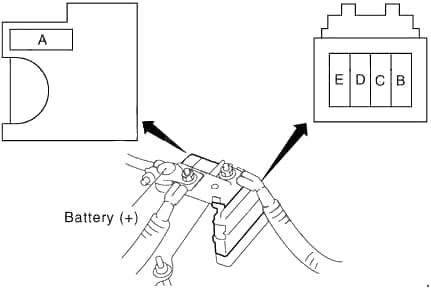
Fusible Link Block
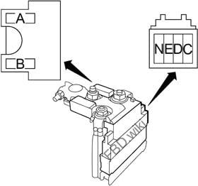
| No. |
A |
Circuit Protected |
| A | 140 | Alternator, Fuse: “C”, “D”, “E” |
| B | 80 | Fuse: “O”, “P”, “Q”, “R” |
| C | 100 | Ignition Relay (Front Wiper High Relay, Fuse: “55”, “56”, “57”, “60”, “61”, “62”), Fuse: “41”, “42”, “43”, “44”, “64” |
| D | 80 | Accessory Relay (Fuse: “18”, “19”, “20”), Ignition Relay No.2 (Fuse: “13”, “14”, “15”), Blower Relay (Fuse: “21”, “22”), Fuse: “5”, “6”, “7”, “8”, “9”, “10”, “11” |
| E | 80 | Fuse: “31”, “32”, “33”, “34”, “35”, “36”, “37”, “38”, “F”, “G”, “H”, “I”, “J”, “K”, “L”, “M” |
| N | 60 | Headlamp High Relay (Fuse: “51”, “52”), Headlamp Low Relay (Fuse: “53”, “54”), Tail Lamp Relay (Fuse: “46”, “47”), Front Fog Lamp Relay (Fuse: “50”), Fuse: “45”, “49” |
WARNING: Terminal and harness assignments for individual connectors will vary depending on vehicle equipment level, model, and market.