Peugeot 108 (2014 – 2018) – fuse box diagram

Peugeot 108 (2014 – 2018) – fuse box diagram

Year of production: 2014, 2015, 2016, 2017, 2018
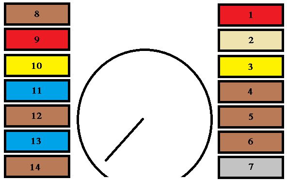
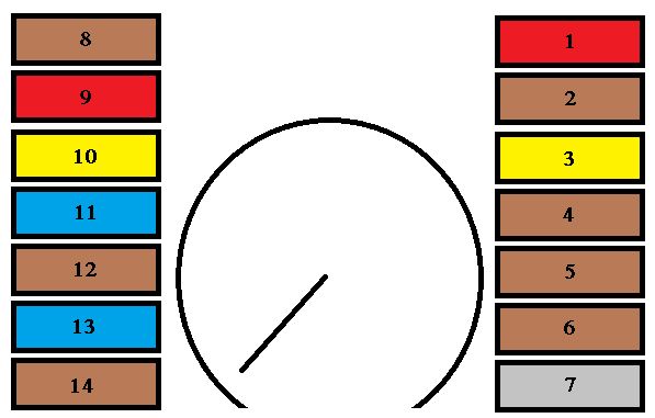
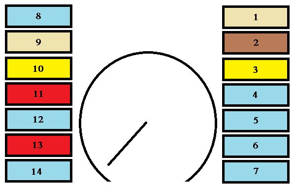
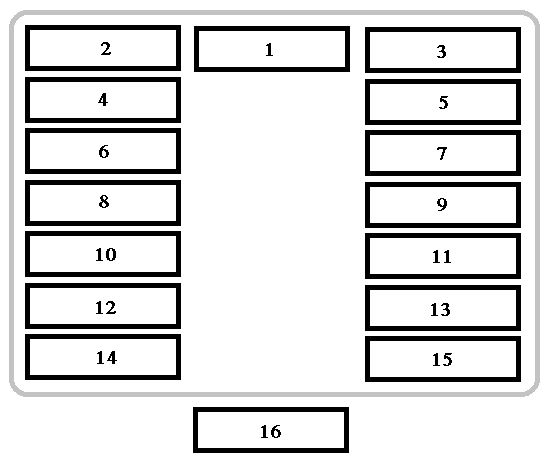
Dashboard fuses

The fusebox is located below the dashboard (driver’s side).
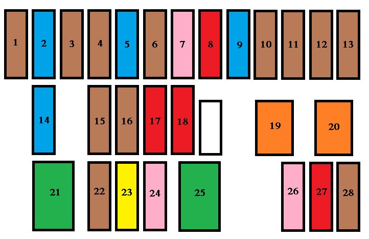
Peugeot 108 - fuse box - dashboard
Peugeot 108 – fuse box – dashboard
Fuse Fuse rating [A] Function
1 5 Fuel injection system – Audio system – VSC system
2 15 Front and rear screenwash
3 5 Main distribution unit – Instrument panel – Display screen – Air conditioning – Heated rear screen and door mirror heating – Electric fabric roof – Audio system
4 5 Electric power steering – Stop & Start
5 15 Rear wiper
6 5 Cooling fan – ABS system ESP – VSC system
7 25 Front wiper
8 10 Heated door mirrors
9 15 12 V socket (120 W max)
10 7,5 Door mirrors – Audio system – Stop & Start – Instrument panel –
Display screen
11 5 Steering lock – Fuel injection system – Electronic gearbox
12 7,5 Airbags
13 5 Instrument panel – Display Screen – Stop & Start
14 15** Steering – Fuel injection system – Brake lamps
7,5*
15 7,5** Fuel injection system – Stop & Start
10*
16 7,5 Engine diagnosis
17 10 Brake lamps – Third brake lamp – Fuel injection system -ABS system – VSC system – Electronic gearbox – Keyless Entry and Starting system
18 10 Sidelamps – Number plate lamps – Rear foglamp – Front foglamps – Rear lamps – Lighting dimmer
19 40 Air conditioning
20 40 Air conditioning – Engine self-diagnosis – Sidelamps – Number
plate lamps – Rear foglamp – Front foglamps – Rear lamps – Lighting dimmer – Brake lamps – Third brake lamp – Fuel injection system – ABS system – VSC system – Electronic gearbox – “Keyless Entry and Starting” system – Electric windows
21 30 Fuel injection system – Stop & Start – Main distribution unit
22** 7,5 Fuel injection system
23** 20 Fuel injection system – Stop & Start
24 25 Main distribution unit
25 30 Electric windows
26 25 Electric windows
27 10 Air conditioning
28 5 Rear foglamp
* VTi 82 engine
** VTi 68 engine

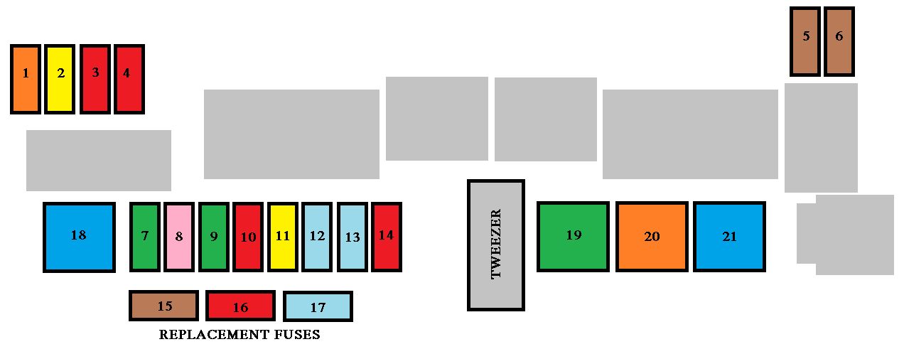
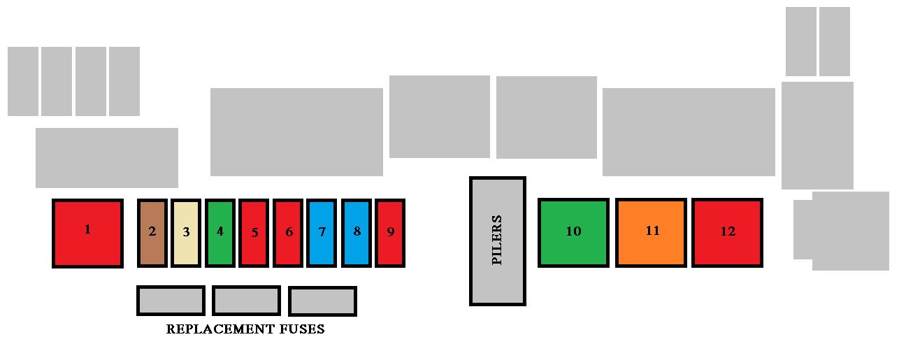
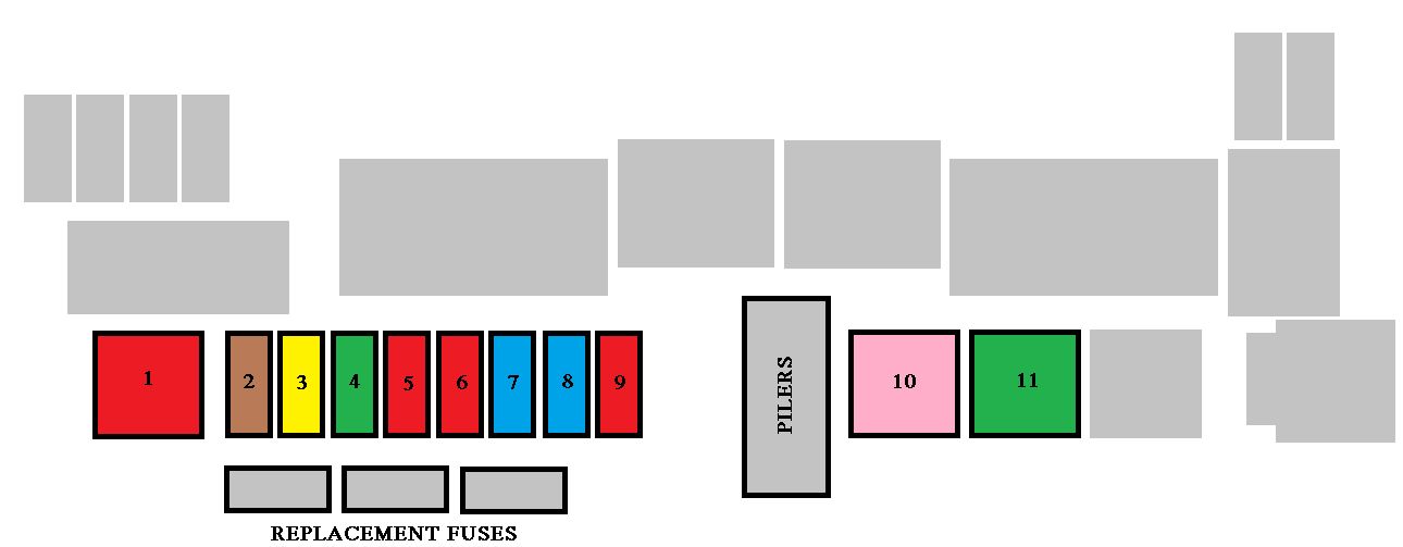
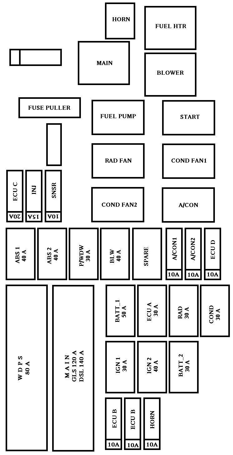
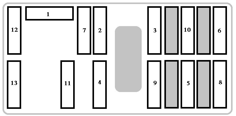
Fuses under the bonnet
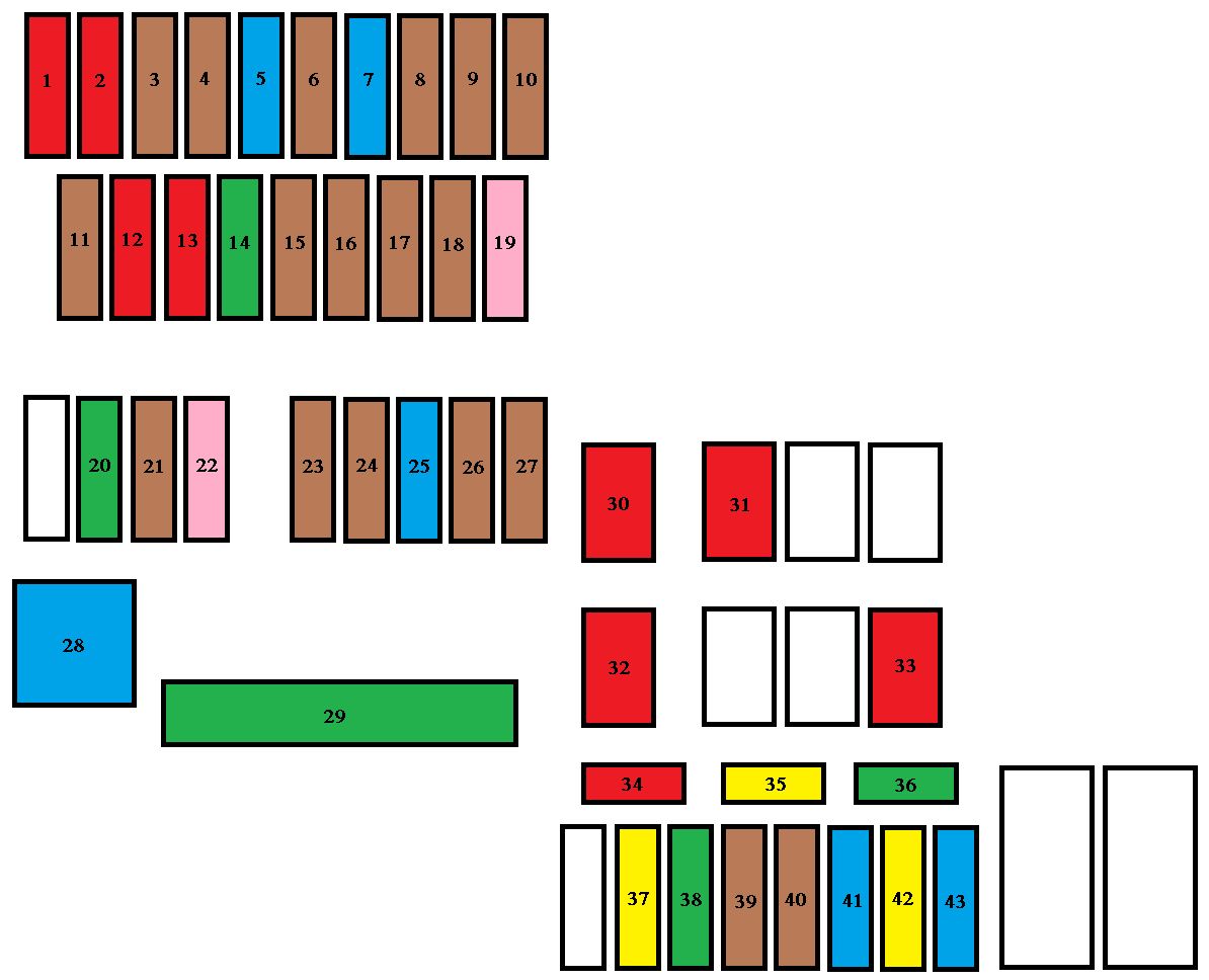
Peugeot 108 - fuse box - engine compartment
Peugeot 108 – fuse box – engine compartment
Fuse Fuse rating [A] Functions
1 10 Right hand dipped beam
2 10 Left hand dipped beam – Headlamp adjustment
3 7,5 Right hand main beam
4 7,5 Left hand main beam
5* 15 Fuel injection system
6* 7,5 Fuel injection system
7* 15 Fuel injection system
8* 7,5 Cooling fan
9 7,5 Air conditioning
10** 7,5 Fuel injection system – Brake lamps – Third brake lamp
11 5 Courtesy lamp – Boot lamp
12 10 Direction indicators – Hazard warning lamps – Instrument panel – Display screen
13 10 Horn
14 30 Distribution units
15** 7,5 Electronic gearbox
16 7,5 Fuel injection system
17 7,5 Keyless Entry and Starting system
18** 7,5 Battery
19 25 Fuel injection system – Cooling fan
20 30 Starter motor
21 7,5 Steering lock
22 25 Front lamps
23 7,5 Fuel injection system
24 7,5 Fuel injection system – Starter motor – Electronic gearbox – Stop & Start
25 15 Audio system – “Keyless Entry and Starting” system
26 7,5 Instrument panel – Display screen
27 7,5 VSC system
28 60 Passenger compartment fusebox
29** 125 Heated rear screen and door mirror heating – Electric fabric roof – ABS system – VSC system – Cooling fan – Front foglamps – LED daytime running lamps
30 50 Electronic gearbox
40 Stop & Start
31 50 Power steering
32 50* Cooling fan
30
40
33 50 ABS system – VSC system
34 10 Spare fuse
35 20 Spare fuse
36 30 Spare fuse
37 20 Heated rear screen and door mirror heating
38 30 ABS system – VSC system
39 7,5 Front foglamps – Instrument panel – Display screen
40 7,5 LED daytime running lamps
41 Not used
42 20 Electric fabric roof
43 Not used

WARNING: Terminal and harness assignments for individual connectors will vary depending on vehicle equipment level, model, and market.

KIA Pride mk3 (2011 – 2014) – fuse box diagram

KIA Pride mk3 (2011 – 2014) – fuse box diagram

Also called:

  • Kia Rio

Year of production: 2011, 2012, 2013, 2014

Instrument panel fuse panel

Fuse name Fuse rating [A] Circuit protected
POWER OUTLET 15 Power Outlet
C/LIGHTER 20 Cigarette Lighter
ACC 10 Front Map Lamp, Power Outside Mirror Switch, BCM, Low DC-DC Convertor, Smart Key Control Module, Audio, A/V & Navigation Head Unit, Digital Clock
A/BAG IND 10 Instrument Cluster
A/BAG 10 SBR PAB Indicator, SRS Control Module Passenger Weight Classification Sensor
MODULE 2 10 BCM
MDPS 2 10 EPS Control Module
WIPER RR 15 Multifunction Switch, Rear Wiper Relay, Rear Wiper Motor
HTD STRG 15 Steering Wheel Heater
FOG LP RR 10
FOG LP FRT 15 Front Fog Lamp Relay
MODULE 1 10 ATM Shift Lever Switch, Door Warning Switch
STOP LP 15 Data Link Connector, Smart Key Control Module, Stop Lamp Switch Stop Lamp Relay, PCB Fuse & Relay Box (HAC Relay)
CLUSTER 10 Audio, BCM, ATM Shift Lever ILL., Crash Pad Switch Instrument Cluster, Tire Pressure Monitoring Module
IG1 1 10 Multipurpose Check Connector, Driver CCS Seat Warmer Module Passenger Seat Warmer Module With ISG : Crash Pad Switch, Low DC-DC Convertor
ABS 3 10 Crash Pad Switch, ESC Module PCB Fuse & Relay Box (HAC Relay)
B/UP LP 10 Back-Up Lamp Switch
PCU 10 Vehicle Speed Sensor, Stop Lamp Switch, Inverter A/C Control Module
HAZARD 15 Hazard Switch, BCM
PDM 1 25 Smart Key Control Module
SUNROOF 15 Sunroof Motor
PDM 2 10 Immobilizer Module, Start/Stop Button Switch, Smart Key Control Module
TCU 15 Smart Key Control Module, Immobilizer Module, ECM/PCM, Transaxle Range Switch
IGN COIL 15 Ignition Coil #1/#2/#3/#4, Condenser
IG2 1 10 BCM, Smart Key Control Module, Driver CCS Seat Warmer Module Cluster Ionizer, Rain Sensor, A/C Control Module, Sunroof Motor PCB Fuse & Relay Box (Blower Relay, Head Lamp (HI) Relay, Fuel Pump #1 Relay)
WIPER FRT 25 Multifunction Switch, Front Wiper Motor PCB Fuse & Relay Box (Rain Sensor Relay, Front Wiper Relay)
DOOR LOCK 20 Door Lock/Unlock Relay, Tail Gate Unlock Relay, Two Turn Unlock Relay
SAFETY POWER WINDOW 25 Driver Safety Power Window Module
S/HEATER 2 15 Seat Warmer Switch, Driver CCS Seat Warmer Module, Passenger Seat Warmer Module
FOLD’G MIRR 10 Power Outside Mirror Switch
ROOM LP 10 BCM, Door Warning Switch, Tire Pressure Monitoring Module Instrument Cluster, Digital Clock, A/C Control Module Luggage Lamp
AUDIO 20 With ISG : Low DC-DC Convertor
W/O ISG : Audio, A/V & Navigation Head Unit
TAIL LP LH 10 Head Lamp LH, License Lamp Rear Combination Lamp (IN/OUT) LH
TAIL LP RH 10 Head Lamp RH, License Lamp, ILL. (+), Rear Combination Lamp (IN/OUT) RH
START 10 With Burglar Alarm : Burglar Alarm Relay
W/O Burglar Alarm : Transaxle Range Switch (A/T), Smart Key Control Module (M/T), Ignition Lock Switch (M/T), ECM (M/T), PCB Fuse & Relay Box (Start Relay) (M/T)
P/WDW LH 25 Power Window Main Switch, Rear Power Window Switch LH Driver Safety Power Window Module
P/WDW RH 25 Power Window Main Switch, Rear Power Window Switch RH Passenger Power Window Switch
HTD MIRR 10 ECM/PCM, A/C Control Module Driver/Passenger Power Outside Mirror
A/CON 10 A/C Control Module

Engine compartment fuse panel

Fuse name Fuse rating [A] Circuit protected
MULTI FUSE MDPS 80 EPS Control Module
ALT 125 Alternator
FUSE B+10 50 I/P Junction Box (Power Connector Fuse : ROOM LP 10A / AUDIO 20A,
Fuse : FOG LP FRT 15A / MODULE 1 10A / STOP LP 15A, Tail Lamp Relay)
INVERTER 40 Inverter
B+2 50 I/P Junction Box (Fuse : HAZARD 15A / PDM 1 25A / PDM 2 10A / SUNROOF 15A /DR LOCK 20A / SAFETY POWER WINDOW 25A / S/HEATER 2 15A, FOLD’G MIRR 10A / Power Window Relay)
IG1 40 With Smart Key – PDM Relay Box (ESCL (ACC) Relay, ESCL (IG1) Relay)
W/O Smart Key – Ignition Switch
ABS1 40 ESC Module, Multipurpose Check Connector
ABS2 40 ESC Module
RR HTD 40 I/P Junction Box (Rear Defogger Relay)
ECU_VM 10 PCM
H/LP HI IND 10 Instrument Cluster

Engine compartment main fuse panel

Fuse name Fuse rating [A] Circuit protected
IG2 40 PCB Fuse & Relay Box (Start Relay), W/O Smart Key – Ignition Switch, With Smart Key – PDM Relay Box (ESCL (IG2) Relay)
ECU1 30 PCB Fuse & Relay Box (Engine Control Relay, ECU2 10A)
BLOWER 40 PCB Fuse & Relay Box (Blower Relay)
C/FAN 40 PCB Fuse & Relay Box (Cooling Fan (Low) Relay, Cooling Fan (Hi) Relay)
F/PUMP1 20 PCB Fuse & Relay Box (Fuel Pump #1 Relay)
H/LP HI 20 PCB Fuse & Relay Box (Head Lamp (HI) Relay)
H/LP 20 PCB Fuse & Relay Box (Head Lamp (LO) Relay)
HORN 10 PCB Fuse & Relay Box (Horn Relay, Burglar Alarm Horn Relay)
ECU2 10 M/T – ECM, A/T – E/R Junction Box (ECU_VM 10A)
B/UP LP 10 A/T – PCM, Transaxle Range Switch
WIPER 10 ECM/PCM, Rain Sensor
ECU4 20 ECM/PCM
INJECTOR 15 ECM/PCM, PCB Fuse & Relay Box (Fuel Pump #1 Relay)
H/LP LH 10 Head Lamp LH
SENSOR1 10 Purge Control Solenoid Valve, Variable Intake Solenoid Valve, Canister Close Valve, PCB Fuse & Relay Box (Cooling Fan (Low) Relay, Cooling Fan (Hi) Relay)
SENSOR2 10 Oil Control Valve #1/#2, Oxygen Sensor (Up/Down)
H/LP RH 10 Head Lamp RH

WARNING: Terminal and harness assignments for individual connectors will vary depending on vehicle equipment level, model, and market

KIA Rio (2011 – 2014) – fuse box diagram

KIA Rio (2011 – 2014) – fuse box diagram

Year of production: 2011, 2012, 2013, 2014

Instrument panel fuse panel

KIA Rio - fuse box diagram - instrument panel
KIA Rio – fuse box diagram – instrument panel
Fuse name Fuse rating [A] Circuit protected
POWER OUTLET 15 Power Outlet
C/LIGHTER 20 Cigarette Lighter
ACC 10 Front Map Lamp, Power Outside Mirror Switch, BCM, Low DC-DC Convertor, Smart Key Control Module, Audio, A/V & Navigation Head Unit, Digital Clock
A/BAG IND 10 Instrument Cluster
A/BAG 10 SBR PAB Indicator, SRS Control Module Passenger Weight Classification Sensor
MODULE 2 10 BCM
MDPS 2 10 EPS Control Module
WIPER RR 15 Multifunction Switch, Rear Wiper Relay, Rear Wiper Motor
HTD STRG 15 Steering Wheel Heater
FOG LP RR 10
FOG LP FRT 15 Front Fog Lamp Relay
MODULE 1 10 ATM Shift Lever Switch, Door Warning Switch
STOP LP 15 Data Link Connector, Smart Key Control Module, Stop Lamp Switch Stop Lamp Relay, PCB Fuse & Relay Box (HAC Relay)
CLUSTER 10 Audio, BCM, ATM Shift Lever ILL., Crash Pad Switch Instrument Cluster, Tire Pressure Monitoring Module
IG1 1 10 Multipurpose Check Connector, Driver CCS Seat Warmer Module Passenger Seat Warmer Module With ISG : Crash Pad Switch, Low DC-DC Convertor
ABS 3 10 Crash Pad Switch, ESC Module PCB Fuse & Relay Box (HAC Relay)
B/UP LP 10 Back-Up Lamp Switch
PCU 10 Vehicle Speed Sensor, Stop Lamp Switch, Inverter A/C Control Module
HAZARD 15 Hazard Switch, BCM
PDM 1 25 Smart Key Control Module
SUNROOF 15 Sunroof Motor
PDM 2 10 Immobilizer Module, Start/Stop Button Switch, Smart Key Control Module
TCU 15 Smart Key Control Module, Immobilizer Module, ECM/PCM, Transaxle Range Switch
IGN COIL 15 Ignition Coil #1/#2/#3/#4, Condenser
IG2 1 10 BCM, Smart Key Control Module, Driver CCS Seat Warmer Module Cluster Ionizer, Rain Sensor, A/C Control Module, Sunroof Motor PCB Fuse & Relay Box (Blower Relay, Head Lamp (HI) Relay, Fuel Pump #1 Relay)
WIPER FRT 25 Multifunction Switch, Front Wiper Motor PCB Fuse & Relay Box (Rain Sensor Relay, Front Wiper Relay)
DOOR LOCK 20 Door Lock/Unlock Relay, Tail Gate Unlock Relay, Two Turn Unlock Relay
SAFETY POWER WINDOW 25 Driver Safety Power Window Module
S/HEATER 2 15 Seat Warmer Switch, Driver CCS Seat Warmer Module, Passenger Seat Warmer Module
FOLD’G MIRR 10 Power Outside Mirror Switch
ROOM LP 10 BCM, Door Warning Switch, Tire Pressure Monitoring Module Instrument Cluster, Digital Clock, A/C Control Module Luggage Lamp
AUDIO 20 With ISG : Low DC-DC Convertor
W/O ISG : Audio, A/V & Navigation Head Unit
TAIL LP LH 10 Head Lamp LH, License Lamp Rear Combination Lamp (IN/OUT) LH
TAIL LP RH 10 Head Lamp RH, License Lamp, ILL. (+), Rear Combination Lamp (IN/OUT) RH
START 10 With Burglar Alarm : Burglar Alarm Relay
W/O Burglar Alarm : Transaxle Range Switch (A/T), Smart Key Control Module (M/T), Ignition Lock Switch (M/T), ECM (M/T), PCB Fuse & Relay Box (Start Relay) (M/T)
P/WDW LH 25 Power Window Main Switch, Rear Power Window Switch LH Driver Safety Power Window Module
P/WDW RH 25 Power Window Main Switch, Rear Power Window Switch RH Passenger Power Window Switch
HTD MIRR 10 ECM/PCM, A/C Control Module Driver/Passenger Power Outside Mirror
A/CON 10 A/C Control Module

Engine compartment fuse panel

KIA Rio - fuse box diagram - engine compartment
KIA Rio – fuse box diagram – engine compartment
Fuse name Fuse rating [A] Circuit protected
MULTI FUSE MDPS 80 EPS Control Module
ALT 125 Alternator
FUSE B+10 50 I/P Junction Box (Power Connector Fuse : ROOM LP 10A / AUDIO 20A,
Fuse : FOG LP FRT 15A / MODULE 1 10A / STOP LP 15A, Tail Lamp Relay)
INVERTER 40 Inverter
B+2 50 I/P Junction Box (Fuse : HAZARD 15A / PDM 1 25A / PDM 2 10A / SUNROOF 15A /DR LOCK 20A / SAFETY POWER WINDOW 25A / S/HEATER 2 15A, FOLD’G MIRR 10A / Power Window Relay)
IG1 40 With Smart Key – PDM Relay Box (ESCL (ACC) Relay, ESCL (IG1) Relay)
W/O Smart Key – Ignition Switch
ABS1 40 ESC Module, Multipurpose Check Connector
ABS2 40 ESC Module
RR HTD 40 I/P Junction Box (Rear Defogger Relay)
ECU_VM 10 PCM
H/LP HI IND 10 Instrument Cluster


Engine compartment main fuse panel

Fuse name Fuse rating [A] Circuit protected
IG2 40 PCB Fuse & Relay Box (Start Relay), W/O Smart Key – Ignition Switch, With Smart Key – PDM Relay Box (ESCL (IG2) Relay)
ECU1 30 PCB Fuse & Relay Box (Engine Control Relay, ECU2 10A)
BLOWER 40 PCB Fuse & Relay Box (Blower Relay)
C/FAN 40 PCB Fuse & Relay Box (Cooling Fan (Low) Relay, Cooling Fan (Hi) Relay)
F/PUMP1 20 PCB Fuse & Relay Box (Fuel Pump #1 Relay)
H/LP HI 20 PCB Fuse & Relay Box (Head Lamp (HI) Relay)
H/LP 20 PCB Fuse & Relay Box (Head Lamp (LO) Relay)
HORN 10 PCB Fuse & Relay Box (Horn Relay, Burglar Alarm Horn Relay)
ECU2 10 M/T – ECM, A/T – E/R Junction Box (ECU_VM 10A)
B/UP LP 10 A/T – PCM, Transaxle Range Switch
WIPER 10 ECM/PCM, Rain Sensor
ECU4 20 ECM/PCM
INJECTOR 15 ECM/PCM, PCB Fuse & Relay Box (Fuel Pump #1 Relay)
H/LP LH 10 Head Lamp LH
SENSOR1 10 Purge Control Solenoid Valve, Variable Intake Solenoid Valve, Canister Close Valve, PCB Fuse & Relay Box (Cooling Fan (Low) Relay, Cooling Fan (Hi) Relay)
SENSOR2 10 Oil Control Valve #1/#2, Oxygen Sensor (Up/Down)
H/LP RH 10 Head Lamp RH

WARNING: Terminal and harness assignments for individual connectors will vary depending on vehicle equipment level, model, and market

Peugeot 107 FL (2012 – 2014) – fuse box diagram

Peugeot 107 FL (2012 – 2014) – fuse box diagram

Year of production: 2012, 2013 ,2014

Instrument panel fuse boxes

These are located on each side of the instrument panel under the trim.

Peugeot 107 FL - fuse box - instrument panel
Peugeot 107 FL – fuse box – instrument panel
Fuse Ampere rating [A] Functions
1 10 Brake lights – ABS – “2 Tronic” gearbox lights
2 25 Central locking/unlocking – Remote control
3 20 Rear screen demisting
4 7,5 Rear lamps – Number plate lamps – Instrument panel – Screen – headlamp adjustment – LED daytime running lamps – Sidelamps
5 7,5 Diagnostic socket
6 7,5 2 Tronic gearbox – Rear foglamp – ESP – LED daytime running lamps – Instrument panel – Rev counter
7 Not used
8 7,5 ABS – Power steering – Air conditioning – Fan assembly
9 10 Reversing lamps – Central locking/unlocking – Electric windows – Rear screen demisting – Speedometer – Air conditioning – Heating – Rev counter – Remote control
10 20 Front and rear wipers and screenwash
11 15 Audio equipment – 12 V socket (120 W max)
12 7,5 eated rear screen – ABS – Fan assembly – Front and rear wipers and screenwash – Power steering – Central locking/unlocking – Air conditioning – Heating – Electric windows – Speedometer – Rev counter – Remote control – Reversing lamp
13 15 Airbag – Fuel injection system – 2 Tronic gearbox – Instrument panel – Rev counter – LED daytime running lamps
14 7,5 Air conditioning – Heating
15 40 Audio system – 12 V socket – Front and rear wipers – Power steering – ABS/ESP – Cooling fan assembly
16 30 Electric windows
17 40 Heating – Air conditioning

Engine compartment fuse box

Peugeot 107 FL - fuse box - engine compartment
Peugeot 107 FL – fuse box – engine compartment
Fuse Ampere rating [A] Functions
1 5 LED daytime running lamps
2 20 Front foglamps
3 10 Left hand front lamp
4 10 Right hand front lamp
5 7,5 2 Tronic gearbox – Fuel injection system
6 7,5 2 Tronic gearbox – Fuel injection system
7 30 LED daytime running lamps – Front foglamps
8 25 ABS
30 ABS/ESP (with VSC)
9 30 Starter motor – Heated rear screen – ABS –
Cooling fan assembly – Front and rear wipers and screenwash – Power steering – Central locking/unlocking – Air conditioning – Heating – Electric windows – Speedometer – Rev counter – Remote control – Reversing lamp – Airbag – Fuel injection system – 2 Tronic gearbox – Instrument panel – LED daytime running lamps
10 10 Hazard warning lamps – Instrument panel – Rev counter – Direction indicators
11 20 Left hand front lamp – Right hand front lamp
12 15 Courtesy lamp – Speedometer – Audio system- Instrument panel – Rev counter
13 15 Fuel injection system – Cooling fan assembly
14 10 Horn
15 7,5 Replacement fuse
16 10 Replacement fuse
17 15 Replacement fuse
18 50 2 Tronic gearbox
19 30 Cooling fan assembly
40
20 40 ABS
50 ABS/ESP (with VSC)
21 50 Power steering

WARNING: Terminal and harness assignments for individual connectors will vary depending on vehicle equipment level, model, and market.

Peugeot 107 FL (2008 – 2011) – fuse box diagram

Peugeot 107 FL (2008 – 2011) – fuse box diagram

Year of production: 2008, 2009, 2010, 2011

Instrument panel fuse boxes

These are located on each side of the instrument panel under the trim.

Peugeot 107 FL - fuse box - instrument panel
Peugeot 107 FL – fuse box – instrument panel
Fuse Ampere rating [A] Functions
1 10 Brake lights – ABS – “2 Tronic” gearbox lights
2 25 Central locking/unlocking
3 20 Rear screen demisting
4 7,5 Rear lights – Number plate lights – Instrument panel – Display
5 7,5 Diagnostic socket
6 7,5 Rear fog lamp – Instrument panel – “2 Tronic” gearbox
7
8 7,5 ABS – Power steering – Air conditioning – Fan assembly
9 10 Rear lights – Central locking/unlocking – Electric windows – Rear screen demisting – Speedometer – Air conditioning – Heating – Rev counter
10 20 Front and rear wipers
11 15 Audio equipment – Electronic engine immobiliser – 12 V socket (120 W max)
12 7,5 Rear screen demisting – ABS – Fan assembly – Front and rear wipers – Power steering – Central locking/unlocking – Air conditioning – Electric windows – Speedometer – Rev counter
13 15 Air bag – Engine control unit – Electronic engine immobiliser – “2 Tronic” gearbox – Instrument panel
14 7,5 Air conditioning
15 40 Accessories – Demisting – ABS – Fan assembly relay – Front and rear wipers
16 30 Electric windows
17 40 Heating – Air conditioning

Engine compartment fuse box

Peugeot 107 FL - fuse box - engine compartment
Peugeot 107 FL – fuse box – engine compartment
Fuse Ampere rating [A] Functions
1 50 2 Tronic gearbox – Fan assembly (diesel)
2 10 Headlamps
20 Headlamps with daytime lights
3 30 ABS control unit
4 30 Ignition switch supply
5 10 Hazard warning lights – Instrument panel warning lights – Direction indicators
6 10 Headlamps
7 15 Courtesy light – Speedometer – Audio equipment – Instrument panel – Rev counter
8 15 Petrol – engine control unit
25 Diesel – engine control unit
9 10 Horn
10 30 Fan assembly (petrol)
11 40 ABS/ESP
12 50 Power steering

WARNING: Terminal and harness assignments for individual connectors will vary depending on vehicle equipment level, model, and market.

Peugeot 107 (2005 – 2007) – fuse box diagram

Peugeot 107 (2005 – 2007) – fuse box diagram

Year of production: 2005, 2006, 2007


Instrument panel fuse boxes

These are located on each side of the instrument panel under the trim.

Peugeot 107 - fuse box - instrument panel
Peugeot 107 – fuse box – instrument panel
Fuse Ampere rating [A] Functions
1 10 Brake lights
2 25 Central locking/unlocking
3 20 Demisting
4 7,5 Rear lights
5 7,5 Diagnostic socket
6 7,5 Rear fog lamp – Instrument panel
7 7,5 Demisting
8 7,5 Injection control unit
9 10 Fuel gauge electrical supply
10 20 Wipers
11 15 Accessories – 12 volt socket
12 7,5 Demisting – ABS – Fan assembly relay – Front and rear wipers
13 15 Air bag control unit – Engine control unit – Engine immobiliser control unit – Ignition coil
14 7,5 Air conditioning
15 40 Accessories – Demisting – ABS – Fan assemby relay – Front and rear wipers
16 30 Electric windows
17 40 Heating


Engine compartment fuse box

Peugeot 107 - fuse box - engine compartment
Peugeot 107 – fuse box – engine compartment
Fuse Ampere rating [A] Functions
1 50 2 Tronic gearbox – Fan assembly (diesel)
2 10 Headlamps
30 Headlamps with daytime lights
3 25 ABS control unit
4 30 Ignition switch supply
5 10 Hazard warning lights
6 10 Headlamps
7 15 Courtesy light
8 15 Petrol – engine control unit
25 Diesel – engine control unit
9 10 Horn
10 30 Fan assembly (petrol)
11 40 ABS

WARNING: Terminal and harness assignments for individual connectors will vary depending on vehicle equipment level, model, and market.

Kia Sephia Sport FL (2009 – 2011) – fuse box diagram

Kia Sephia Sport FL (2009 – 2011) – fuse box diagram

Also called:

  • Kia Rio
  • Kia New Pride
  • Kia Rio Xcite

Year of production: 2009, 2010, 2011

Engine compartment

KIA Rio FL mk2 - fuse box - engine compartment
KIA New Sephia FL – fuse box – engine compartment
Description Fuse rating [A] Protected component
BATT_1 50 Alternator, Battery
ECU A 30 Engine control unit
RAD 30 Radiator fan
COND 30 Condenser fan
ECU B 10 Engine control unit
SPARE Spare fuse
HORN 10 Horn
IGN1 30 Ignition
IGN2 40 Ignition
BATT_2 Alternator, Battery
MAIN 125 Alternator
MDPS 80 Power steering wheel
ABS1 40 ABS
ABS2 40 ABS
P/WDW 30 Power window
BLW 40 Blower
SPARE Spare fuse
A/CON1 10 Air conditioner
A/CON2 10 Air conditioner
ECU D 10 Engine control unit
SNSR 10 Sensor
INJ 15 Injector
ECU C 20 Engine control unit
SPARE Spare fuse
SPARE Spare fuse
HORN Horn relay
MAIN Main relay
FUEL PUMP Fuel pump relay
RAD FAN Radiator fan relay
COND FAN2 Condenser fan relay
FUEL HTR Fuel filter heater relay
BLOWER Blower motor relay
START Start motor relay
COND FAN1 Condenser fan relay
A/CON Air conditioner relay

Driver-side knee bolster

KIA Rio mk2 - fuse box - driver's side knee bloster
KIA New Sephia FL – fuse box – driver’s side knee bloster
Description Fuse rating [A] Protected component
RR WIPER 15 Rear wiper
H/LP (LH) 10 Headlight (left)
FR WIPER 25 Front wiper
BLOWER 10 Blower
H/LP(RH) 10 Headlight (right)
S/ROOF 20 Sunroof
STOP LP 15 Stop light
C/DR LOCK 20 Central door lock
IGN COIL 15 Ignition coil
ABS 10 ABS
B/UP LP 10 Back-up light
SPARE Spare fuse
C/LIGHTER 25 Cigar lighter
FOLD’G 10 Outside rearview mirror folding
HTD SEAT 20 Seat warmer
AMP 25 Amplifier
FR FOG LP 10 Front fog light
SPARE Spare fuse
ECU 10 Engine control unit
CLUSTER 10 Cluster
P/WDW RH 25 Power window (right)
AUDIO 10 Audio
RR FOG LP 10 Rear fog light
IGN 10 Ignition
HTD GLASS 30 Rear window defroster
A/BAG 15 Air bag
TCU 10 Automatic transaxle control
SNSR 10 Sensor
SPARE Spare fuse
MULT B/UP 10 Cluster, ETACS, A/C, Clock, Room lamp
AUDIO 15 Audio
P/WDW LH 25 Power window (left)
HTD MIRR 10 Outside rearview mirror heater
TAIL LP(LH) 10 Taillight (left)
TAIL LP(RH) 10 Taillight (right)
HAZARD 10 Hazard warning light
T/SIG LP 10 Turn signal light
A/BAG IND 10 Air bag warning
START 10 Start motor

WARNING: Terminal and harness assignments for individual connectors will vary depending on vehicle equipment level, model, and market.

Kia New Pride FL (2009 – 2011) – fuse box diagram

Kia New Pride FL (2009 – 2011) – fuse box diagram

Also called:

  • Kia Rio
  • Kia Sephia Sport
  • Kia Rio Xcite

Year of production: 2009, 2010, 2011

Engine compartment

KIA Rio FL mk2 - fuse box - engine compartment
KIA New Pride FL – fuse box – engine compartment
Description Fuse rating [A] Protected component
BATT_1 50 Alternator, Battery
ECU A 30 Engine control unit
RAD 30 Radiator fan
COND 30 Condenser fan
ECU B 10 Engine control unit
SPARE Spare fuse
HORN 10 Horn
IGN1 30 Ignition
IGN2 40 Ignition
BATT_2 Alternator, Battery
MAIN 125 Alternator
MDPS 80 Power steering wheel
ABS1 40 ABS
ABS2 40 ABS
P/WDW 30 Power window
BLW 40 Blower
SPARE Spare fuse
A/CON1 10 Air conditioner
A/CON2 10 Air conditioner
ECU D 10 Engine control unit
SNSR 10 Sensor
INJ 15 Injector
ECU C 20 Engine control unit
SPARE Spare fuse
SPARE Spare fuse
HORN Horn relay
MAIN Main relay
FUEL PUMP Fuel pump relay
RAD FAN Radiator fan relay
COND FAN2 Condenser fan relay
FUEL HTR Fuel filter heater relay
BLOWER Blower motor relay
START Start motor relay
COND FAN1 Condenser fan relay
A/CON Air conditioner relay

Driver-side knee bolster

KIA Rio mk2 - fuse box - driver's side knee bloster
KIA New Pride FL – fuse box – driver’s side knee bloster
Description Fuse rating [A] Protected component
RR WIPER 15 Rear wiper
H/LP (LH) 10 Headlight (left)
FR WIPER 25 Front wiper
BLOWER 10 Blower
H/LP(RH) 10 Headlight (right)
S/ROOF 20 Sunroof
STOP LP 15 Stop light
C/DR LOCK 20 Central door lock
IGN COIL 15 Ignition coil
ABS 10 ABS
B/UP LP 10 Back-up light
SPARE Spare fuse
C/LIGHTER 25 Cigar lighter
FOLD’G 10 Outside rearview mirror folding
HTD SEAT 20 Seat warmer
AMP 25 Amplifier
FR FOG LP 10 Front fog light
SPARE Spare fuse
ECU 10 Engine control unit
CLUSTER 10 Cluster
P/WDW RH 25 Power window (right)
AUDIO 10 Audio
RR FOG LP 10 Rear fog light
IGN 10 Ignition
HTD GLASS 30 Rear window defroster
A/BAG 15 Air bag
TCU 10 Automatic transaxle control
SNSR 10 Sensor
SPARE Spare fuse
MULT B/UP 10 Cluster, ETACS, A/C, Clock, Room lamp
AUDIO 15 Audio
P/WDW LH 25 Power window (left)
HTD MIRR 10 Outside rearview mirror heater
TAIL LP(LH) 10 Taillight (left)
TAIL LP(RH) 10 Taillight (right)
HAZARD 10 Hazard warning light
T/SIG LP 10 Turn signal light
A/BAG IND 10 Air bag warning
START 10 Start motor

WARNING: Terminal and harness assignments for individual connectors will vary depending on vehicle equipment level, model, and market.

Kia Rio (2010 – 2011) – fuse box diagram

Kia Rio (2010 – 2011) – fuse box diagram

Year of production: 2010, 2011

Engine compartment

KIA Rio FL mk2 - fuse box - engine compartment
KIA Rio FL mk2 – fuse box – engine compartment
Description Fuse rating [A] Protected component
BATT_1 50 Alternator, Battery
ECU A 30 Engine control unit
RAD 30 Radiator fan
COND 30 Condenser fan
ECU B 10 Engine control unit
SPARE Spare fuse
HORN 10 Horn
IGN1 30 Ignition
IGN2 40 Ignition
BATT_2 Alternator, Battery
MAIN 125 Alternator
MDPS 80 Power steering wheel
ABS1 40 ABS
ABS2 40 ABS
P/WDW 30 Power window
BLW 40 Blower
SPARE Spare fuse
A/CON1 10 Air conditioner
A/CON2 10 Air conditioner
ECU D 10 Engine control unit
SNSR 10 Sensor
INJ 15 Injector
ECU C 20 Engine control unit
SPARE Spare fuse
SPARE Spare fuse
HORN Horn relay
MAIN Main relay
FUEL PUMP Fuel pump relay
RAD FAN Radiator fan relay
COND FAN2 Condenser fan relay
FUEL HTR Fuel filter heater relay
BLOWER Blower motor relay
START Start motor relay
COND FAN1 Condenser fan relay
A/CON Air conditioner relay

Driver-side knee bolster

KIA Rio mk2 - fuse box - driver's side knee bloster
KIA Rio FL mk2 – fuse box – driver’s side knee bloster
Description Fuse rating [A] Protected component
RR WIPER 15 Rear wiper
H/LP (LH) 10 Headlight (left)
FR WIPER 25 Front wiper
BLOWER 10 Blower
H/LP(RH) 10 Headlight (right)
S/ROOF 20 Sunroof
STOP LP 15 Stop light
C/DR LOCK 20 Central door lock
IGN COIL 15 Ignition coil
ABS 10 ABS
B/UP LP 10 Back-up light
SPARE Spare fuse
C/LIGHTER 25 Cigar lighter
FOLD’G 10 Outside rearview mirror folding
HTD SEAT 20 Seat warmer
AMP 25 Amplifier
FR FOG LP 10 Front fog light
SPARE Spare fuse
ECU 10 Engine control unit
CLUSTER 10 Cluster
P/WDW RH 25 Power window (right)
AUDIO 10 Audio
RR FOG LP 10 Rear fog light
IGN 10 Ignition
HTD GLASS 30 Rear window defroster
A/BAG 15 Air bag
TCU 10 Automatic transaxle control
SNSR 10 Sensor
SPARE Spare fuse
MULT B/UP 10 Cluster, ETACS, A/C, Clock, Room lamp
AUDIO 15 Audio
P/WDW LH 25 Power window (left)
HTD MIRR 10 Outside rearview mirror heater
TAIL LP(LH) 10 Taillight (left)
TAIL LP(RH) 10 Taillight (right)
HAZARD 10 Hazard warning light
T/SIG LP 10 Turn signal light
A/BAG IND 10 Air bag warning
START 10 Start motor

WARNING: Terminal and harness assignments for individual connectors will vary depending on vehicle equipment level, model, and market.

Peugeot 106 (1996 – 2003) – fuse box diagram

Peugeot 106 (1996 – 2003) – fuse box diagram

Year of production: 1996, 1997, 1998, 1999, 2000, 2001, 2002, 2003

Engine compartment

16 fuse box (engine compartment)

The 16 fuse boxes and maxi fuse boxes are located under the bonnet.

Peugeot 106 DAG - fuse - box - engine compartment
Peugeot 106 – fuse – box – engine compartment
Fuse Ampere rating [A] Functions
1 Not used
2 30 Anti-lock braking system
3 25 Engine cooling
4 20 Anti-lock braking system
5 25 Fan unit
6 20 Additional driving lamps
7 Not used
8 Not used
9 10 Fuel pump
10 Not used
11 10 Oxygen sensor
12 10 Left-hand main beam
13 10 Right-hand main beam
14 10 Left-hand dipped beam
15 10 Right-hand dipped beam
16 30 Pulsair pump

Maxi fuse (engine compartment)

Peugeot 106 DAG - fuse box - engine compartment - maxi fuse
Peugeot 106 – fuse box – engine compartment – maxi fuse
Fuse Ampere rating [A] Functions
MF1 20 Lighting switch
MF2 80 Ignition supply (starter +ve)
MF3 40 Ignition supply (ignition controlled +ve)
MF4 40 Battery +ve feed to 13-fuse box

Passenger compartment

13 fuse box (passenger compartment)

Peugeot 106 DAG - fuse box - passenger compartment
Peugeot 106 – fuse box – passenger compartment
Fuse Ampere rating [A] Functions
1 Not used
2 25 Heater blower
3 25 Heated rear screen – air conditioning – pressure switch – heated seats
4 25 Radio – map reading light
5 30 Heated rear screen – horn – lighter + heated mirrors
6 10 Direction indicators / hazard warning lights
7 10 Engine cooling – electronic immobiliser – coolant temperature control unit – instrument panel – power steering – reversing lights
8 20 Central locking – electronic immobiliser – interior lighting – boot lighting – coolant temperature control unit – instrument panel – radio – clock
9 30 Electric windows – hazard warning lights – electric mirrors – brake lights – front and rear wipers – instrument panel
10 20 Front electric windows
11 5 Rear fog light + instrument panel lights
12 5 Left tail-light – front sidelights – instrument panel lighting (rheostat) + headlamp height adjustment
13 5 Switch lighting – radio panel lighting  – number plate lighting – right tail light

WARNING: Terminal and harness assignments for individual connectors will vary depending on vehicle equipment level, model, and market.