Year of production: 2001, 2002, 2003, 2004, 2005, 2006
Underhood Fuses (Power Distribution Center)
Power Distribution Center is located in the engine compartment; near the air cleaner. The identity of each fuse is indicated on the backside of the cover.
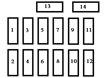
Chrysler Sebring mk1 Sedan – fuse box – power distribution box
Cavity
Fuse
Circuit
1
30 Amp Green
Blower Motor
2
10 Amp Red
Right High Beam Headlight, High Beam Indicator
3
10 Amp Red
Left High Beam Headlight
4
15 Amp Blue
Power Door Lock Switch Illumination, Transmission Range Switch, Daytime Running Light Module (Canada), Power Windows, Anti-lock Brake System Module
5
10 Amp Red
Power Door Lock and Door Lock Arm/Disarm Switches, Vanity, Reading, Map, Rear Seating, Ignition, and Trunk Lights, Illuminated Entry, Radio, Power Antenna, Data Link Connector, Body Control Module, Power Amplifier
6
10 Amp Red
Heated Rear Window Indicator
7
20 Amp Yellow
Instrument cluster illumination, Park and tail Lights
8
20 Amp Yellow
Power Receptacle, Horns, Ignition, Fuel, Start
9
15 Amp Blue
Power Door Lock Motors (Body Control Module)
10
20 Amp Yellow
Daytime Running Light Module (Canada)
11
10 Amp Red
Instrument Cluster, Transmission Control, Park/Neutral Switch, Body Control Module
12
10 Amp Red
Left Low beam Headlight
13
20 Amp Yellow
Right Low Beam Headlight, Fog Light Switch
14
10 Amp Red
Radio
15
10 Amp Red
Turn Signal and Hazard Flashers, Wiper Switch, Seat Belt Control Module, Wiper Relays, Rear Window Defroster Relay
16
10 Amp Red
Airbag Control Module
17
10 Amp Red
Airbag Control Module
18
20 Amp C/BRKR
Power Seat Switch, Remote Trunk Release
19
30 Amp C/BRKR
Power Windows
WARNING: Terminal and harness assignments for individual connectors will vary depending on vehicle equipment level, model, and market.
Year of production: 2005, 2006, 2007, 2008, 2009, 2010
Underhood Fuses (Power Distribution Center)
Power Distribution Center is located in the engine compartment; next to the air cleaner filter. A label identifying the components and circuits is located on the underside of the cover.
Chrysler PT Cruiser Convertible – fuse box – power distribution center
Fuse
Amp/Color
Description
1
30 Amp/Pink
Ignition Start
2
40 Amp/ Green
Anti-Lock Brake (ABS) Pump
3
40 Amp/ Green
Ignition Run
4
30 Amp/Blue
Heated Seats
5
40 Amp/ Green
Radiator Fan (Low Speed Turbo only)
6
50 Amp/Red
High Speed Radiator Fan (Turbo Only)
7
30 Amp/Blue
Anti-Lock Brake (ABS) Solenoid
8
40 Amp/ Green
Electric Back Light (EBL)
9
40 Amp/ Green
Power Top
10
40 Amp/ Green
IP Fuse Block
11
10 Amp/Red
Air Conditioning (A/C)
12
15 Amp/Lt. Blue
Stop Lights
13
20 Amp/ Yellow
Fuel Pump/Auto Shut Down (ASD)
14
15 Amp/Lt. Blue
Horn
15
20 Amp/ Yellow
Electronic Automatic Transaxle (ETAX)
16
—
—
17
15 Amp/Lt. Blue
Hi Beam
18
30 Amp/Blue
Ignition Off Draw (IOD)
19
15 Amp/Lt. Blue
Hazard Flasher
20
20 Amp/ Yellow
Power Outlets
21
Spare
22
20 Amp/ Yellow
Fog Lamps (Export Only)
Interior Fuses
The fuse access panel is on the left side of the instrument panel next to the steering column. A label identifying the components and circuits is located on the inside of the cover.
Fuse
Amp/Color
Description
1
25 Amp/ Natural
Headlamp Switch
2
15 Amp/Lt. Blue
Park Lamps
3
20 Amp/ Yellow
RKE/Door Locks
4
20 Amp/ Yellow
Power Height Adjust
5
10 Amp/Red
Airbag Run Only
6
10 Amp/Red
B/U Electric Back Light (EBL) NEU SAF
7
25 Amp/ Natural
HVAC Blower
8
15 Amp/Lt. Blue
Fog Lamp (Non BUX)
9
10 Amp/Red
Airbag Run-ST
10
10 Amp/Red
Cluster/RKE/SKIM
11
10 Amp/Red
Engine Module/ABSTRAC
12
10 Amp/Red
PDC Relays/LDP
13
10 Amp/Red
Interior Lighting
14
20 Amp/ Yellow
Overhead Console/Radio
15
20 Amp/ Yellow
Wipers/Comb. FLS
16
10 Amp/Red
Auto Stick/Ignition
17
15 Amp/Lt. Blue
Heated Seats
18
10 Amp/Red
Heated Mirrors
19
10 Amp/Red
Rt Headlamp
20
10 Amp/Red
Lt Headlamp
WARNING: Terminal and harness assignments for individual connectors will vary depending on vehicle equipment level, model, and market.
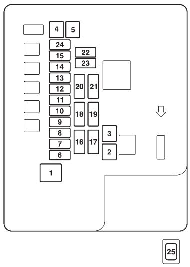
Chrysler PT Cruiser (2005 – 2010) – fuse box diagram
Year of production: 2005, 2006, 2007, 2008, 2009, 2010
Integrated Power Module (IPM)
Integrated Power Module is located in the engine compartment near the air cleaner assembly. A description of each fuse and component may be stamped on the inside of the cover.
Cavity
Cartridge fuse
Mini fuse
Description
1
40 Amp Green
Power Top Feed — Convertible Only
2
20 Amp Yellow
AWD ECU Feed
3
10 Amp Red
CHMSL Brake Switch Feed
10 Amp Red
Ignition Switch Feed
5
20 Amp Yellow
Trailer Tow
6
10 Amp Red
IOD Sw/ Pwr Mir/ Ocm Steering Cntrl Sdar/Hfm
7
30 Amp Green
IOD Sense1
8
30 Amp Green
IOD Sense2
9
40 Amp Green
Power Seats
10
20 Amp Yellow
CCN, Power Locks
11
15 Amp Lt Blue
Power Outlet
12
20 Amp Yellow
Ign Run/ Acc Inverter
13
20 Amp Yellow
Pwr run/ Acc Outlet RR
14
10 Amp Red
IOD CCN/ Interior Lighting
15
50 Amp Red
RAD Fan Relay Battery Feed
16
15 Amp Lt. Blue
IGN Run/ Acc Cigar Ltr/Sunroof
17
10 Amp Red
IOD Feed CVT Mod/ Mod_Wcm
18
40 Amp Green
ASD Relay Contact PWR Feed
19
20 Amp Yelow
PWR Amp 1 & Amp 2 Feed
20
15 Amp Lt. Blue
IOD Feed Radio
21
10 Amp Red
IOD Feed Intrus Mod/Siren
22
10 Amp Red
IGN RUN Hvac/ Compass Sensor
23
15 Amp Lt. Blue
ENG ASD Relay Feed 3
24
25 Amp Natural
WR Sunroof Feed
25
10 Amp Red
Heated Mirror
26
15 Amp Lt. Blue
ENG ASD Relay Feed 2
27
10 Amp Red
IGN RUN Only ORC Feed
28
10 Amp Red
IGN RUN ORC/OCM Feed
29
—
—
Empty
30
20 Amp Yellow
Heated Seats
31
10 Amp Red
Headlamp Washer Relay Control
32
30 Amp Pink
ENG ASD Control Feed 1
33
10 Amp Red
ABS MOD/ J1962 Conn/PCM
34
30 Amp Pink
ABS Valve Feed
35
40 Amp Green
ABS Pump Feed
36
30 Amp Pink
Headlamp Washer Control
37
25 Amp Natura
Spare
WARNING: Terminal and harness assignments for individual connectors will vary depending on vehicle equipment level, model, and market.
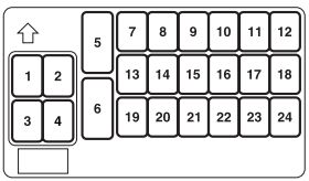
Chrysler PT Cruiser (2001 – 2005) – fuse box diagram
Year of production: 2001, 2002, 2003, 2004, 2005
Underhood fuses (Power Distribution Center)
Power Distribution Center is located in the engine compartment (next to the air cleaner filter). A label identifying the components and circuits is located on the underside of the cover.
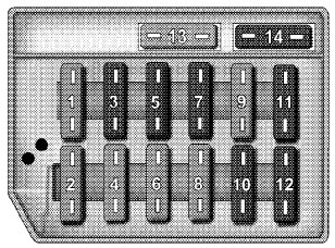
Chrysler PT Cruiser – fuse box – power distribution center
Fuse
Ampere/Color
Description
1
30 Amp/Pink
Ignition Start
2
40 Amp/Green
Anti-Lock Brake (ABS) Pump
3
40 Amp/Green
Ignition Run
4
30 Amp/Blue
Heated Seats
5
40 Amp/Green
Radiator Fan
6
20 Amp/Blue
Power Height Adjuster
7
30 Amp/Blue
Anti-Lock Brake (ABS) Solenoid
8
40 Amp/Green
Electric Back Light (EBL)
9
—
Spare
10
40 Amp/Green
Exterior Lighting, Remote Keyless Entry, Alarm and Door Locks
11
10 Amp/Red
Air Conditioning (A/C)
12
15 Amp/Lt. Blue
Stop Lights
13
20 Amp/Blue
Fuel Pump/Auto Shut Down (ASD)
14
15 Amp/Lt. Blue
Horn
15
20 Amp/Blue
Electronic Automatic Transaxle (ETAX)
16
15 Amp/Lt. Blue
Hi Beam
17
20 Amp/ Yellow
Ignition Off Draw (IOD)
18
15 Amp/Lt. Blue
Hazard
19
20 Amp/ Yellow
Power Outlets
20
—
Spare
21
20 Amp/ Yellow
Fog Lights (Build-Up Export Only
22
—
Spare
Interior Fuses
The fuse access panel is on the left side of the instrument panel next to the steering column. A label identifying the components and circuits is located on the inside of the cover.
WARNING: Terminal and harness assignments for individual connectors will vary depending on vehicle equipment level, model, and market.
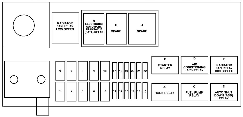
Chrysler Pacifica (2003 – 2008) – fuse box diagram
Year of production: 2003, 2004, 2005, 2006, 2007, 2008
Integrated power module (IPM)
Integrated Power Module is located in the engine compartment near the battery. A label that identifies each component is printed on the inside of the cover.
Cavity
Mixa fuse
Description
1
40 Amp Green
Anti-Lock Brake System (ABS) Pump
2
—
Spare
3
30 Amp Pink
Ignition Off Draw (IOD)
4
40 Amp Green
Body Control Module (BCM) Feed 1
5
40 Amp Green
Electronic Back Light (EBL)
6
30 Amp Pink
Front Wipers
7
40 Amp Green
Starter
8
40 Amp Green
Power Seat C/B
9
40 Amp Green
Power Sunroof
10
—
Spare
11
40 Amp Green
Headlight Washer, Power Liftgate
12
—
Spare
13
40 Amp Green
Radiator Fan 1
14
—
Spare
15
40 Amp Green
Anti-Lock Brake System (ABS) Module
40
40 Amp Green
Driver Door Node
41
40 Amp Green
Passenger Door Node
42
40 Amp Green
Front Blower
24
20 Amp Yellow
Power Outlet (Selectable)
25
15 Amp Blue
Radio, Amplifier, Navigation, Hands-Free Phone (HFM), Electronic Vehicle Information Center (EVIC), EC, SNRF, Mirror
26
20 Amp Yellow
Power Outlet
27
—
Spare
28
25 Amp Natural
Horn
29
20 Amp Yellow
Cluster, CHMSL, Stop Lights, Anti-Lock Brake System (ABS)
30
10 Amp Red
Ignition Switch
31
20 Amp Yellow
Hazard
34
—
Spare
35
—
Spare
36
20 Amp Yellow
Electronic Automatic Transaxle (EATX) Solenoid
37
25 Amp Natural
ASD
38
20 Amp Yellow
Fuel Pump
39
20 Amp Yellow
A/C Clutch, MTV
44
25 Amp Natural
Rear Heated Seats
45
10 Amp Red
Anti-Lock Brake System (ABS) Ignition Run
46
20 Amp Yellow
Passenger Door
47
20 Amp Yellow
Driver Door
48
15 Amp Blue
PLG, OHC, Body Control Module (BCM), Navigation, Hands-Free Phone (HFM)
49
25 Amp Natural
Amplifier
50
15 Amp Blue
HVAC, DVD, RAD, CLK, SKREEM
WARNING: Terminal and harness assignments for individual connectors will vary depending on vehicle equipment level, model, and market.
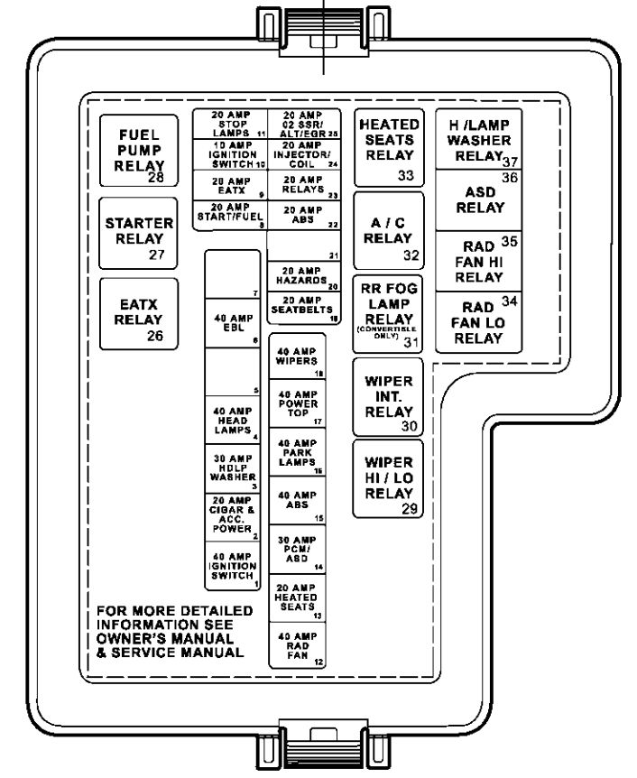
Chrysler Concorde mk2 (1998 – 2004) Second Generation – fuse box diagram
Year of production: 1998, 1999, 2000, 2001, 2002, 2003, 2004
Interior Fuses
The fuse block is behind the end cover at the left side of the instrument panel. The location and identification of fuse block relays can be found on the inside of the instrument panel end cover.
High Beam Relay, High Beam Indicator, High Beam Switch
12
15 Amp Lt. Blue
Left Low Beam Headlight
13
10 Amp Red
Fuel Pump Relay, Power Train Control Module
14
10 Amp Red
Cluster, Day/Night Mirror, Sunroof, Overhead Console, Garage Door Opener, Body Control Module
15
10 Amp Red
Daytime Running Light Module (Canada)
16
20 Amp Yellow
Fog Light Indicator
17
10 Amp Red
ABS Control, Back Up Lights, Daytime Running Lights, A/C Heater Control
18
20 Amp Yellow
Power Amplifier, Horn
19
15 Amp Lt. Blue
Overhead Console, Garage Door Opener, Trunk, Overhead, Rear Reading, and Visor Vanity Lights, Trunk Release Solenoid, Power Mirrors, Power Door Locks, Body Control Module, Aspirator Motor
20
20 Amp Yellow
Brake Lights
21
10 Amp Red
Leak Detection Pump, Low Rad Relay, High Rad Relay, A/C Clutch Relay
22
10 Amp Red
Airbag
23
30 Amp Green
Blower Motor, ATC Power Module
24
20 Amp C/BRKR
Power Window Motors
25
20 Amp C/BRKR
Power Door Lock Motors, Power Seats
Underhood Fuses
Power Distribution center is located in the engine compartment. A label which identifies these components is located on the underside of the cover
WARNING: Terminal and harness assignments for individual connectors will vary depending on vehicle equipment level, model, and market.
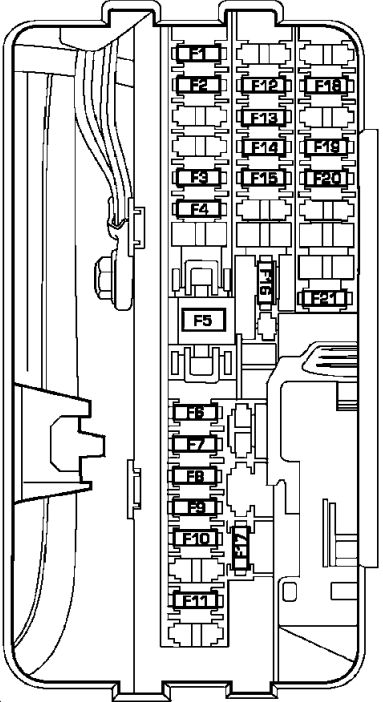
The fuse block contains blade-type mini-fuses, relays, and circuit breakers for high-current circuits. It is located in the left kick panel. It is accessible through a snap-in cover.
Chrysler Aspen – fuse box – interior
Cavity
Mini fuse/color
Description
F1
15 Amp Blue
Instrument Cluster Battery Feed
F2
10 Amp Red
Spare
F3
10 Amp Red
Ignition Run/Start for Next Generation Controller (NGC), Integrated Power Module (IPM), AC Relay and Fuel Pump Relay
F4
10 Amp Red
Door Node and NonMemory Power Mirror Switch Battery Feed
F5
(2) 10 Amp Red
Airbags (2 Fuses in Yellow Holder)
F6
2 Amp Clear
Ignition Run/Start Unlock
F7
25 Amp Natural
Radio Battery Feed
F8
10 Amp Red
Ignition Run/Start for Cluster/Transfer Case/Seat Sw. Back lighting
F9
10 Amp Red
Satellite Digital Audio Receiver (SDAR)/ Digital Video Disc (DVD) Battery Feed
F10
10 Amp Red
Spare
F11
10 Amp Red
Heated Mirrors
F12
20 Amp Yellow
Cluster Battery Feed
F13
10 Amp Red
Ignition Run HVAC Module/Heated Rear Glass (EBL) Relay
F14
10 Amp Red
ABS Module Ignition Run
F15
15 Amp Blue
Battery Feed Blue Tooth, Compass/Trip Computer (CMTC), Sentry Key Diagnostics
F16
20 Amp Yellow
Reconfigurable Power Outlets
F17
20 Amp Yellow
Ignition Run / Rear Park Assist / Second Row Heated Seats
F18
20 Amp Yellow
Cigar Lighter Ignition
F19
10 Amp Red
Spare Fuse
F20
15 Amp Blue
Heating & Air Conditioning w/ATC Only Battery Feed
F21
25 Amp Natural
Amplifier Battery Feed
Fuses (Power Distribution Center)
Power distribution center located in the left side of the engine compartment.
Cavity
Cartidge/fuse relay
Mini fuse
Description
1
30
—
Starter
2
30
—
Front Wiper
3
40
—
Brake Batt
4
30
—
JB Feed Acc # 2
5
40
—
Power Seats
6
30
—
Run Remote Relay Feed
7
40
—
Blower Motor Relay Feed
8
40
—
JB Feed Acc Delay
9
Spare
—
Spare
10
30
—
ASD
11
40
—
Power Liftgate ( If Equipped)
12
40
—
JB Feed / Heated Rear Glass (EBL)/ T Case Brake
13
30
—
JB Feed RR
14
40
—
ESP Pump
15
50
—
JB Feed
16
—
10
Spare
17
—
Spare
Spare
18
—
20
Fuel Pump
19
—
20
Next Generation Controller (NGC)
20
—
25
115v Power Inverter
21
—
20
ABS Batt
22
—
20
Next Generation Controller (NGC) Batt
23
—
20
Trailer Tow
24
—
15
A/C Clutch
25
—
15
Stop Lamp Switch
26
—
Spare
Spare
27
—
20
Run/Start Relay Feed
28
—
Spare
Spare
29
Relay
—
Run Start
30
Relay
—
Run Remote
31
Spare
—
—
32
Relay
—
Starter
33
Relay
—
Electronic Automatic Transaxle (EATX)
34
Relay
—
AC Clutch
35
Relay
—
Fuel Pump Rly
36
Spare
—
Spare
37
Relay
—
Stop Lamp Switch
38
Spare
—
Spare
39
Relay
—
Blower Motor
40
Relay
—
Auto Shut Down (ASD) Rly
Fuses (Integrated Power Module)
Integrated Power Module is located in the left side of the engine compartment.
Cavity
Cartridge fuse/ relay
Mini fuse
Description
1
Relay
—
Wiper On/Off Rly
2
Relay
—
Wiper Hi/Lo Rly
3
Relay
—
Horn Rly
4
Relay
—
Rear Wiper Rly
5
Relay
—
Lt Trailer-Tow Stop/ Turn Rly
6
Relay
—
Rt Trailer-Tow Stop/ Turn Rly
7
Relay
—
Park Lamps Rly
8
—
10
Lt Park Lamps
9
—
10
Trailer-Tow Park Lamps
10
—
10
Rt Park Lamps
11
Relay
—
Radiator Fan Hi Rly
12
—
20
Front Control Module (FCM) Batt #4
13
—
20
Front Control Module (FCM) Batt #2
14
—
20
Adjustable Pedal
15
—
20
Ft Fog Lamps
16
—
20
Horn
17
—
20
Rear Wiper
18
—
20
Front Control Module (FCM) Batt #1
19
—
20
Lt Trailer-Tow Stop/ Turn
20
—
20
Front Control Module (FCM) Batt #3
21
—
20
Rt Trailer-Tow Stop/ Turn
22
30
—
Front Control Module (FCM) BATT # 5
23
40
—
Radiator Fan
24
Relay
—
Radiator Fan Lo Rly
25
Relay
—
Ft Fog Lamps Rly
26
Relay
—
Adjustable Pedal Rly
27
—
30
Ignition Off Draw (IOD) #1
28
—
30
Ignition Off Draw (IOD) #2
29
—
—
Spare
30
—
—
Spare
WARNING: Terminal and harness assignments for individual connectors will vary depending on vehicle equipment level, model, and market.