Chrysler 300C mk2 (from 2011) – fuse box diagram
Year of production: 2011, 2012, 2013, 2014, 2015, 2016
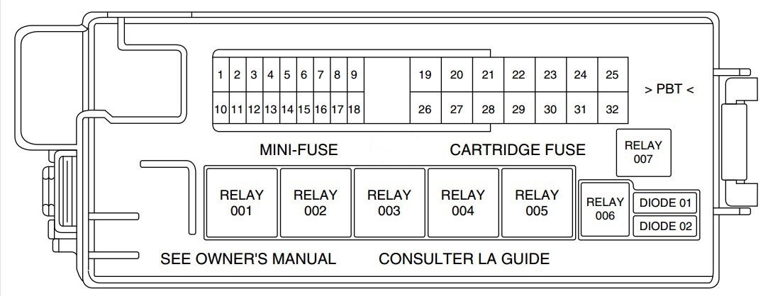
Front Power Distribution Center
The Front Power Distribution Center is located in the engine compartment. This module contains fuses and relays.
| Cavity | Cartridge fuse | Mini fuse | Description |
| 1 | — | — | Fuse – Spare |
| 2 | 40 Amp Green | — | Radiator Fan #1 |
| 3 | 50 Amp Red | — | Power Steering #1 |
| 4 | 30 Amp Pink | — | Starter |
| 5 | 40 Amp Green | — | Anti-Lock Brakes |
| 6 | 25 Amp Natural | — | Anti-Lock Brakes |
| 7 | — | — | Fuse – Spare |
| 8 | — | — | Fuse – Spare |
| 9 | — | 20 Amp Yellow | All-Wheel Drive Module – If Equipped |
| 10 | — | — | Security |
| 11 | — | 20 Amp Yellow | Horns |
| 12 | — | 10 Amp Red | Air Conditioning Clutch |
| 13 | — | — | Fuse – Spare |
| 14 | — | — | Fuse – Spare |
| 15 | — | 25 Amp Natural | Transmission |
| 16 | — | — | Fuse – Spare |
| 18 | 50 Amp Red | — | Radiator Fan #2 |
| 19 | 50 Amp Red | — | Power Steering #2 |
| 20 | 30 Amp Pink | — | Wiper Motor |
| 21 | 30 Amp Pink | — | Headlamp Washers |
| 22 | — | — | Fuse – Spare |
| 23 | — | — | Fuse – Spare |
| 24 | — | — | Fuse – Spare |
| 28 | — | 25 Amp Natural | Fuel Pump |
| 29 | — | 15 Amp Blue | Transmission Shifter |
| 30 | — | — | Fuse – Spare |
| 31 | — | 25 Amp Natural | Engine Module |
| 32 | — | — | Fuse – Spare |
| 33 | — | — | Fuse – Spare |
| 34 | — | 25 Amp Natural | Powertrain #1 |
| 35 | — | 20 Amp Yellow | Powertrain #2 |
| 36 | — | 10 Amp Red | Anti-Lock Brake Module |
| 37 | — | 10 Amp Red | Engine Controller/Rad Fan Relays |
| 38 | — | 10 Amp Red | Airbag Module |
| 39 | — | 10 Amp Red | Power Steering Module/AC Clutch Relay |
| 48 | — | 10 Amp Red | AWD Module/Front Axle Disconnect |
| 49 | — | — | Fuse – Spare |
| 50 | — | — | Fuse – Spare |
| 51 | — | 20 Amp Yellow | Vacuum Pump |
| 52 | — | — | Fuse – Spare |
| 53 | — | — | Fuse – Spare |
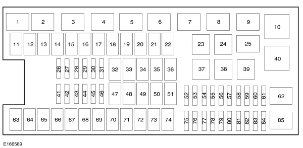
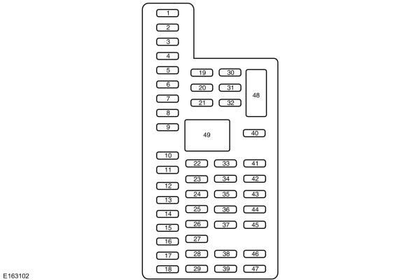
Rear Power Distribution Center
There is also a power distribution center located in the trunk under the spare tire access panel. This center contains fuses and relays.
| Cavity | Cartridge fuse | Mini fuse | Description |
| 2 | 60 Amp Yellow | — | Front PDC Feed #1 |
| 3 | — | — | Fuse – Spare |
| 4 | 60 Amp Yellow | — | Front PDC Feed #2 |
| 5 | 30 Amp Pink | — | Sunroof |
| 6 | 40 Amp Green | — | Exterior Lighting #1 |
| 7 | 40 Amp Green | — | Exterior Lighting #2 |
| 8 | 30 Amp Pink | — | Interior Lighting/Washer Pump |
| 9 | 30 Amp Pink | — | Power Locks |
| 10 | 30 Amp Pink | — | Driver Door |
| 11 | 30 Amp Pink | — | Passenger Door |
| 12 | — | 20 Amp Yellow | Cigar Lighters, Instrument Panel & Power Outlet Console Rear |
| 15 | 40 Amp Green | — | HVAC Blower |
| 16 | — | — | Fuse — Spare |
| 17 | — | — | Fuse — Spare |
| 18 | — | — | Fuse — Spare |
| 19 | — | — | Fuse — Spare |
| 20 | — | — | Fuse — Spare |
| 21 | — | — | Fuse — Spare |
| 22 | — | — | Fuse — Spare |
| 23 | — | 10 Amp Red | Fuel Door/Diagnostic Port |
| 24 | — | 15 Amp Blue | Radio Screen |
| 25 | — | 10 Amp Red | Tire Pressure Monitor |
| 26 | — | — | Fuse — Spare |
| 27 | — | 25 Amp Natural | Amplifier |
| 31 | — | 25 Amp Natural | Power Seats |
| 32 | — | 15 Amp Blue | HVAC Module/Cluster |
| 33 | — | 15 Amp Blue | Ignition Switch/Wireless Module |
| 34 | — | 10 Amp Red | Steering Column Module/Clock |
| 35 | — | 10 Amp Red | Battery Sensor |
| 36 | — | — | Fuse — Spare |
| 37 | — | 15 Amp Blue | Radio |
| 38 | — | 20 Amp Yellow | Power Outlet Inside Arm Rest |
| 40 | — | — | Fuse — Spare |
| 41 | — | — | Fuse — Spare |
| 42 | 30 Amp Pink | — | Rear Defrost |
| 43 | — | 25 Amp Natural | Rear Heated Seats/Steering Wheel |
| 44 | — | 10 Amp Red | Park Assist/Blind Spot/Camera |
| 45 | — | 15 Amp Blue | Cluster/Rearview Mirror/Compass |
| 46 | — | 10 Amp Red | Adaptive Cruise Control |
| 47 | — | 10 Amp Red | Adaptive Front Lighting |
| 48 | — | 20 Amp Yellow | Active Suspension |
| 49 | — | — | Fuse — Spare |
| 50 | — | — | Fuse — Spare |
| 51 | — | 20 Amp Yellow | Front Heated Seats |
| 52 | — | 10 Amp Red | Heated Cupholders/Rear Heated Seat Switches |
| 53 | — | 10 Amp Red | HVAC Module/In Car Temperature Sensor |
| 54 | — | — | Fuse — Spare |
| 55 | — | — | Fuse — Spare |
| 56 | — | — | Fuse — Spare |
| 57 | — | — | Fuse — Spare |
| 58 | — | 10 Amp Red | Airbag Module |
| 59 | — | — | Fuse — Spare |
| 60 | — | — | Fuse — Spare |
| 61 | — | — | Fuse — Spare |
| 62 | — | — | Fuse — Spare |
| 63 | — | — | Fuse — Spare |
| 64 | — | 25 Amp Natural | Rear Windows |
| 65 | — | 10 Amp Red | Airbag Module |
| 66 | — | — | Fuse — Spare |
| 67 | — | 15 Amp Blue | Run Sense |
| 68 | — | 15 Amp Blue | Illumination/Rear Sunshade |
| 69 | — | — | Fuse — Spare |
| 70 | — | — | Fuse — Spare |
WARNING: Terminal and harness assignments for individual connectors will vary depending on vehicle equipment level, model, and market.