Jeep Grand Cherokee (2014) – fuse box diagram

Jeep Grand Cherokee (2014) – fuse box diagram

Year of production: 2014

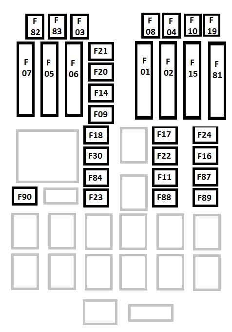
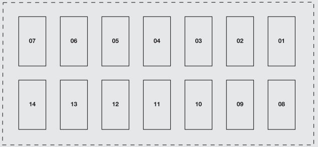
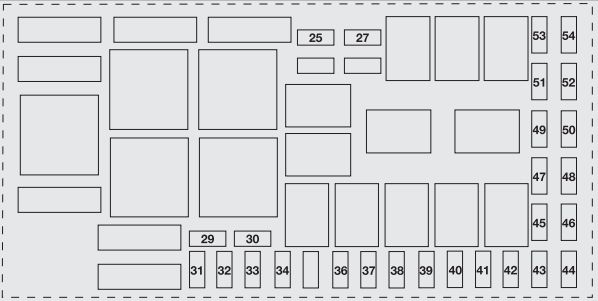
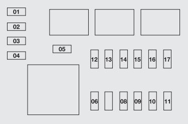
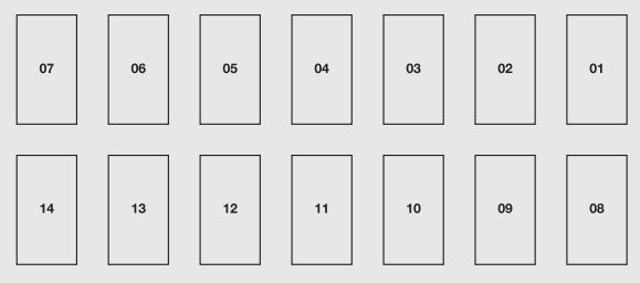
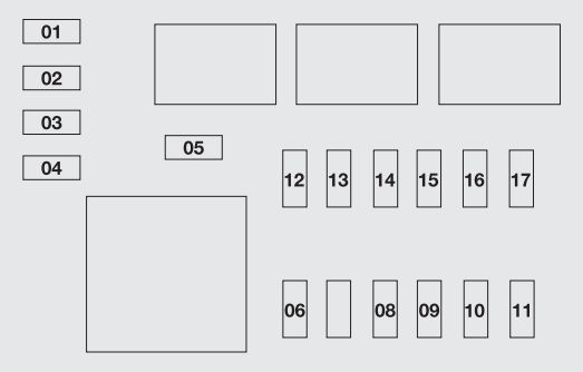
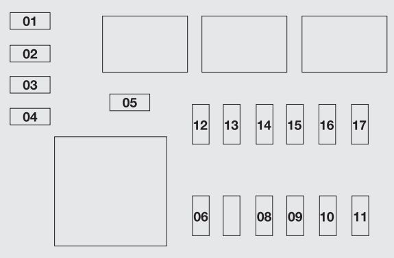
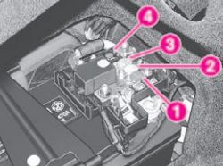
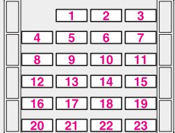
Power distribution center

The Power Distribution Center is located in the engine compartment near the battery.

Cavity Cartridge fuse Micro fuse Description
F03 60 Amp Yellow Rad Fan
F05 40 Amp Green Compressor for Air Suspension if equipped
F06 40 Amp Green Antilock Brakes/Electronic Stability Control Pump
F07 40 Amp Green Starter Solenoid
F08 40 Amp Green Emission sensors (Diesel engine only)
F09 40 Amp Green Diesel Fuel Heater (Diesel engine only)
F10 40 Amp Green Body Controller / Exterior Lighting #2
F11 30 Amp Pink Trailer Tow Electric Brake – If Equipped
F12 40 Amp Green Body Controller #3 / Interior Lights
F13 40 Amp Green Blower Motor Front
F14 40 Amp Green Body Controller #4 / Power Locks
F17 30 Amp Pink Headrest Release – If Equipped
F20 30 Amp Pink Passenger Door Module
F22 20 Amp Yellow Engine Control Module
F23 30 Amp Pink Body Controller #1
F24 30 Amp Pink Driver Door Module
F25 30 Amp Pink Front Wipers
F26 30 Amp Pink Antilock Brakes/Stability Control Module/Valves
F28 20 Amp Yellow Trailer Tow Backup Lights – If Equipped
F29 20 Amp Yellow Trailer Tow Parking Lights – If Equipped
F30 30 Amp Pink Trailer Tow Receptacle – If Equipped
F32 30 Amp Pink Drive Train Control Module
F34 30 Amp Pink Slip Differential Control
F35 30 Amp Pink Sunroof – If Equipped
F36 30 Amp Pink Rear Defroster
F37 30 Amp Pink Rear Blower – If Equipped
F38 30 Amp Pink Power Inverter 115V AC – If Equipped
F39 30 Amp Pink Power Liftgate – If Equipped
F40 10 Amp Red Daytime Running Lights
F42 20 Amp Yellow Horn
F44 10 Amp Red Diagnostic Port
F46 10 Amp Red Tire Pressure Monitor
F49 10 Amp Red Integrated Central Stack / Climate Control
F50 20 Amp Yellow Air Suspension Control Module – If Equipped
F51 10 Amp Red Ignition Node Module / Keyless Ignition / Steering Column Lock
F52 5 Amp Tan Battery Sensor
F53 20 Amp Yellow Trailer Tow – Left Turn/Stop Lights – If Equipped
F56 15 Amp Blue Additional Content (Diesel engine only)
F57 15 Amp Blue Transmission
F59 10 Amp Red Purging Pump (Diesel engine only)
F60 15 Amp Blue Transmission Control Module
F62 10 Amp Red Air Conditioning Clutch
F63 20 Amp Yellow Ignition Coils (Gas), Urea Heater (Diesel)
F64 25 Amp Natura Fuel Injectors / Powertrain
F66 10 Amp Red Sunroof / Passenger Window Switches / Rain Sensor
F67 15 Amp Blue CD / DVD / Bluetooth Hands-free Module – If Equipped
F68 20 Amp Yellow Rear Wiper Motor
F70 20 Amp Yellow Fuel Pump Motor
F71 30 Amp Green Audio Amplifier
F73 15 Amp Blue HID Headlamps Right
F74 20 Amp Yellow Brake Vacuum Pump – If Equipped
F76 10 Amp Red Antilock Brakes/Electronic Stability Contro
F77 10 Amp Red Drivetrain Control Module/Front Axle Disconnect Module
F78 10 Amp Red Engine Control Module / Electric Power Steering – If Equipped
F80 10 Amp Red Universal Garage Door Opener / Compass / Anti-Intrusion Module
F81 20 Amp Yellow Trailer Tow Right Turn/Stop Lights
F82 10 Amp Red Steering Column Control Module/ Cruise Control
F83 10 Amp Red Fuel Door
F84 15 Amp Blue Switch Bank/Instrument Cluster
F85 10 Amp Red Airbag Module
F86 10 Amp Red Airbag Module
F87 10 Amp Red Air Suspension / Trailer Tow / Steering Column Control Module
F88 15 Amp Blue Instrument Panel Cluster
F90/91 20 Amp Yellow Power Outlet (Rear seats) Selectable
F91 10 Amp Red Rear Console Lamp – If Equipped
F93 20 Amp Yellow Cigar Lighter
F94 10 Amp Red Shifter / Transfer Case Module
F95 10 Amp Red Rear Camera / Park Assist
F96 10 Amp Red Rear Seat Heater Switch / Flashlamp Charger – If Equipped
F97 25 Amp Natural Rear Heated Seats & Heated Steering Wheel – If Equipped
F98 25 Amp Natural Front Heated Seats – If Equipped
F99 10 Amp Red Climate Control / Driver Assistance Systems Module
F100 10 Amp Red Active Damping – If Equipped
F101 15 Amp Blue Electrochromatic Mirror/Smart High Beams – If Equipped
F103 10 Amp Red Cabin Heater (Diesel engine only)
F104 20 Amp Yellow Power Outlets (Instrument Panel/Center Console)

WARNING: Terminal and harness assignments for individual connectors will vary depending on vehicle equipment level, model, and market.

Jeep Cherokee KL (from 2013) – fuse box diagram

Jeep Cherokee KL (from 2013) – fuse box diagram

Year of production: 2013, 2014, 2015, 2016

Power Distribution Center

The Power Distribution Center is located in the engine compartment near the battery. This center contains cartridge fuses, mini-fuses and relays. A label that identifies each component is printed on the inside of the cover.

Cavity Blade Fuse Cartridge Fuse Description
F06 Not used
F07 15A Blue Powertrain Control Module – PCM
F08 25A Clear Engine Control Module (ECM)
F09 Not used
F10 20A Yellow Power Takeoff Unit (PTU)
F11 Not used
F12 20A Yellow Brake Vacuum Pump – If Equipped
F13 10A Red Engine Control Module (ECM)
F14 10A Red Drivetrain Control Module (DTCM) / Power Take-Off Unit (PTU) – If Equipped / Brake System Module (BSM)
F15 Not used
F16 20A Yellow Powertrain
F17 Not used
F18 Not used
F19 40A Green Starter Solenoid
F20 10A Red A/C Compressor Clutch
F21 Not used
F22 5A Tan Radiator Fan
F23 70A Tan Body Controller Module (BCM) – Feed 1
F24 Not used
F25 Not used
F26 30A Pink Fuel Heater – Diesel Only
F27 Not Used
F28 15A Blue Transmission Control Module (TCM)
F29 Not Used
F30 10A Red Engine Control Module (ECM)
F31 Not Used
F32 Not Used
F33 30A Pink Driver Door Module (DDM) – If Equipped
F34 30A Pink Body Controller Module (BCM) – Feed 3
F35 Not Used
F36 Not Used
F37 50A Red Voltage Stabilization Module (VSM) – If Equipped With Stop/Start Engine Option
F38 60A Yellow Glow Plugs – Diesel Only – If Equipped
F39 40A Green HVAC Blower Motor
F40 20A Blue Trailer Tow Park Light – If Equipped
F41 60A Yellow Body Controller Module (BCM) – Feed 2
F42 30A Pink Electric Park Brake (EPB) – Left
F43 20A Yellow Trailer Tow Left Stop/Turn Light – If Equipped
F44 30A Pink Trailer Tow / 7-Way Connector – If Equipped
F45 30A Pink Passenger Door Module (PDM) – If Equipped
F46 25A Clear Sunroof / Skyslider – If Equipped
F47 30A Pink Drivetrain Control Module (DTCM)
F48 Not Used
F49 30A Pink Power Inverter (115V A/C) – If Equipped
F50 30A Pink Power Liftgate – If Equipped
F51 Not Used
F52 Not Used
F53 30A Pink BSM-ECU & Valves
F54 30A Pink Urea Heater Control Unit – If Equipped With Diesel Engine
F55 10A Red Blind Spot Sensors / Compass / Rearview Camera If Equipped / Rear Seat Heater Switches / Trunk Lamp W/ Flashlamp Charger
F56 15A Blue Ignition Node Module (IGNM)/ KIN/RF Hub/ Electric Steering Column Lock (ESL)
F57 20A Yellow Fuel Pump Motor
F58 10A Red Occupant Classification Module
F59 Not used
F60 20A Yellow Power Outlet – Center Console
F61 Not used
F62 10A Red Heated Mirrors – If Equipped
F63 25A Clear Front Heated Seats – If Equipped
F64 25A Clear Heated Steering Wheel / Rear Heated Seats – If Equipped
F65 15A Blue HVAC (ECC) / Instrument Panel Cluster (IPC)
F66 10A Red In Car Temperature Sensor / Humidity Sensor / Driver Assist System Module (DASM) / Park Assist (PAM)
F67 Note used
F68 Note used
F69 10A Red Power Transfer Unit Switch (TSBM) / Active Grill Shutter (AGS) – If Equipped
F70 Note used
F71 20A Yellow Windshield DeIcer – If Equipped
F72 5A Tan Intelligent Battery Sensor (IBS) If Equipped With Stop/Start Engine Option
F72 20A Yellow Trailer Tow RT Stop / Turn Lights – If Equipped
F73 30A Pink Rear Defroster / Defogger
F74 20A Blue Engine Control Module (ECM) Gasoline Engine – If Equipped
F75 20A Yellow Cigar Lighter
F76 20A Yellow Rear Differential Module (RDM) – If Equipped
F77 10A Red Fuel Door Release/Brake Pedal Switch
F78 10A Red Diagnostic Port / Steering Column Control Module (SCCM) / Digital TV – If Equipped
F79 10A Red Integrated Center Stack (ICS) / HVAC / Aux Switch Bank Module (ASBM) / Instrument Panel Cluster (IPC)
F80 20A Yellow Radio / CD – If Equipped
F81 Not Used
F82 Not Used
F83 30A Pink Headlamp Washer Pump – If Equipped
F84 40A Green Brake System Module (BSM) – Pump Motor If Equipped With Diesel Engine
F84 20A Blue Trailer Tow Backup Lights – If Equipped With Gasoline Engine
F85 Not Used
F86 Not Used
F87 Not Used
F88 15A Blue Collision Mitigation Module (CMM) / Electrochromatic Mirror / Smart Camera Module – If Equipped
F89 10A Red Headlamp Leveling – If Equipped
F90 Not Used
F91 Not Used
F92 20A Yellow Rear Power Outlet
F93 40A Green Brake System Module (BSM) – Pump Motor – If Equipped With Gasoline Engine
F94 30A Pink Electric Park Brake (EPB) – Right
F95 10A Red Electrochromatic Mirror / Rain Sensor / Sunroof – If Equipped
F96 10A Red Occupant Restraint Controller (ORC)
F97 10A Red Occupant Restraint Controller (ORC)
F98 25A Clear Audio Amplifier – If Equipped
F99 30A Pink Trailer Tow Module – If Equipped With Gasoline Engine
F100 Not used

Interior Fuses

The interior fuse panel is located in the passenger compartment on the left side dash panel under the instrument panel.

Cavity Blade Fuse Description
F13 15A Blue Low Beam Left
F32 10A Red Interior Lighting
F36 10A Red Intrusion Module/ Siren – If Equipped
F38 20A Yellow Deadbolt All Unlock
F43 20A Yellow Washer Pump Front
F48 25A Clear Fog Lamp Rear Left/Right – If Equipped
F49 7,5A Brown Lumbar Support
F50 7,5A Brown Wireless Charging Pad If Equipped
F51 10A Red Driver Window Switch/Power Mirrors – If Equipped
F53 7,5A Brown UCI Port (USB & AUX)
F89 10A Red Door Locks – Driver Unlock
F91 7,5A Brwon Fog Lamp Front Left
F92 7,5A Brown Fog Lamp Front Right
F93 10A Red Low Beam Right

WARNING: Terminal and harness assignments for individual connectors will vary depending on vehicle equipment level, model, and market.

Jeep Renegade (2014 – 2015) – fuse box diagram

Jeep Renegade (2014 – 2015) – fuse box diagram

Year of production: 2014, 2015

Engine compartment fuse box

The engine compartment fuse panel is located on the left side of the engine compartment.

Jeep Renegade - fuse box - engine compartment
Jeep Renegade – fuse box – engine compartment
Cavity Maxi fuse Cartridge fuse Micro fuse Description
F01 70 Module Body Computer
F02 70 Module Body Computer, Rear Distribution Units
F03 20 Controller Power Supply Body Computer
F04 30 Brake Control Electronics Module
F05 70 Electric Power-Assisted Steering
F06 20 Engine Cooling fan
F07 40 – 1.4
Without A/C
Engine Cooling fan
50 – 1.4
With A/C And All 2.4
Models
F08 30 Automatic Transmission, GSM
F09 5 Control Module Engine
F10 15 Horn
F11 10 – 1.4 Engines Supply Secondary Loads
25 – 2.4
Engines
F14 7,5 Heater “Blow By”
F15 40 Brake Control Module Pump
F16 5 Engine Control Module Power, Automatic Transmission
F17 10 –  1.4 Engines Supply Primary Loads
15 – 2.4 Engines
F18 20 12V Rear Cargo Outlet Ignition Powered
F19 7,5 Air Conditioner Compressor
F20 5 Electronic Power Four-Wheel
Drive
F21 15 Fuel Pump
F22 20 Power Control Module Engine
F23 30 Heated Windshield – If Equipped
F24 15 Electronic Unit Supply Automatic Transmission
F30 20 Customer
Installed)
12V Rear Cargo Outlet Constant
Battery Powered
F83 40 Air Conditioning Fan
F84 30 Power Supply All Wheel
Drive
F87 5 Shift Lever Automatic Transmission
F88 7,5 Heated Outside Mirrors
F89 30 Heated Rear Window
F30 5 IBS Sensor (Battery State Of Charge

Dashboard fuse box (Body Computer Fuse Center)

The controller is located at the left side of the steering column at the bottom of the instrument panel.

Jeep Renegade - fuse box - dashboard
Jeep Renegade – fuse box – dashboard
Cavity Mini fuse Description
F31 7,5 Flashes/Electrical Movement Front Seats/Fan Air Conditioning
F33 20 Power Window Front (Driver Side)
F34 20 Power Window Front (Passenger Side)
F36 15 Supply Uconnect® System, Air Conditioning, Alarm, Power Folding Outside Mirrors, USB Port
F37 10 System Power Forward Collision Warning Plus, All Wheel Drive (AWD), IPC
F38 20 Central Locking
F42 7,5 Power Under Lock and Key
F43 20 Bi-directional Pump Washer
F47 20 Power Rear Window (Driver Side)
F48 20 Power Rear Window (Passenger Side)
F49 7,5 Supply ParkSense, Spot Lights Front Dome, Mirror, Electric Motor Retractable Roof, Heated Front Seats, Stabilizer Battery, ESC System, ESL
F50 7,5 Supply Air Bag
F51 7,5 Alarm Power, Front Courtesy Light, Air Conditioning Compressor, Brake Pedal Switch (NC), Plaque Automatic Transmission, Compass, Rear Camera, Leveling Headlights, Air Conditioning
F53 7,5 Supply IPC/Starter Device/System Keyless Enter-N-Go
F94 15 Power Socket

Rear Cargo Fuse/Relay Distribution Unit

The configuration of the luggage compartment varies in accordance with the equipment on the vehicle

Fuse box version A

Jeep Renegade - fuse box - boot compartment - version A
Jeep Renegade – fuse box – boot compartment – version A
Cavity Mini fuse Description
F1 30 Power Inverter
F2 20 HIFI Audio System
F3 20 MY SKY
F4 7,5 Lumbar Adjustment Front Seat (Driver Side)
F5 30 Power Seat (Driver Side)
F6 7,5 Power Seat (Driver Side And Passenger Side)
F7 30 Lumbar Adjustment Front Seats (Driver Side And Passenger Side)
F8 20 Heating Front Seats
The fuse box also has a 20 A protective fuse for the sun visor of the retractable roof.

Fuse box version B

Jeep Renegade - fuse box - boot compartment - version B
Jeep Renegade – fuse box – boot compartment – version B
Cavity Mini fuse description
F1 10 Controller Exterior Lighting On
Trailer
F5 15 Controller Exterior Lighting Lights (Drivers Side)
F6 15 Controller Exterior Lighting Lights (Passenger Side)

WARNING: Terminal and harness assignments for individual connectors will vary depending on vehicle equipment level, model, and market.

Abarth Grande Punto (2007 – 2010) – fuse box diagram

Abarth Grande Punto (2007 – 2010) – fuse box diagram

Year of production: 2007, 2008, 2009, 2010

Fuse box on dashboard

Fiat Grande Punto - fuse box - dashboard
Abarth Grande Punto – fuse box – dashboard
Users Fuse Ampere rating [A]
Free 01
Power + battery instrument panel, EOBD diagnostic socket 02 10
Power + battery sound system, control unit for hands free kit with voice recognition and Bluetooth® technology, control unit for Hi-Fi audio system 03 15
Power + battery ignition switch 04 7,5
Power for windscreen/rear window washer motor pump 05 20
Power for tailgate actuator 05 15
Power for door lock motor actuators, dead lock motor actuators 07 20
Free 08
Power for front ceiling light, rear ceiling light, boot light, puddle light, courtesy lights 09 10
Power + key electric power steering system control unit 10 7,5
Power + key instrument panel, switch on brake pedal (brake light control circuit), switch on clutch pedal 11 7,5
Power + key brake system control unit, VDC system, switch on brake pedal 12 7,5
Power + key air bag system control unit 13 10
Power + key side button panel light, steering wheel control lights, central button panel (ASR control and led) 14 7,5
Power + key button panel light on ceiling light, front seat warming button panel (system control and led), rain sensor 14 7,5
Power + key power sunroof control unit, tyre pressure sensor control unit, control unit for hands free kit with voice recognition and Bluetooth® technology, parking sensor system control unit 14 7,5

Fuse box in engine compartment

Fiat Grande Punto - fuse box - engine compartment
Abarth Grande Punto – fuse box – engine compartment
Users Fuse Ampere rating [A]
Power + brake system battery (solenoid valves) 53 30
Left dipped beam power, headlight aiming device 38 10
Right dipped beam power 39 10
Left main beam power 40 10
Right main beam power 41 10
Power + key engine control unit 47 7,5
Power + key passenger’s compartment cooling unit, electronic control unit for driver’s window, power door mirrors, reversing light (1.4 8v Dualogic version) 48 7,5
Free 46
Power for engine diagnosis system secondary loads 34 15
Power for engine diagnosis system primary loads (ignition coils, injectors, engine control unit – Multijet versions) 30 15
Power for engine control unit (1.4 engine) 33 10
Power for fuel motor pump 51 15
Power for front fog lights 25 15
Power for headlight washer motor pump 27 30
Power for single tone horn 37 15
Power for conditioner compressor 42 7,5
Power for starter motor (magnet + 50) 49 30
Power for slider solenoid valve (1.4 16V engine) 29 7,5
Power + battery internal cooling control unit 54 7,5
Power + battery engine control unit 32 7,5
Power for passenger’s compartment current outlet 31 20
Power + key reversing light, glow plug control unit, flow meter, water in diesel fuel sensor 45 10
Power for electric door mirror defrosting devices 43 10
Power for front passenger’s power window motor 26 20
Power for driver’s power window motor 28 20
Free 52
Free 44

Fuse box in the boot

Fiat Grande Punto - fuse box - boot compartment
Abarth Grande Punto – fuse box – boot compartment
Users Fuse Ampere rating [A]
Free 01
Free 02
Free 03
Power for driver’s seat lumbar adjustment motor 04 10
Power for boot current outlet 05 15
Free 06
Free 07
Power for driver’s seat warming unit 08 10
Power for passenger’s seat warming unit 09 10
Power + battery power window motor on right rear door 10 20
Power + battery power window motor on left rear door 11 20
Free 12
Free 13
Free 14
Power + battery tyre pressure monitoring system control unit 15 10
Power + battery hi-fi system subwoofer 16 20
Power + battery power sunroof system 17 20

WARNING: Terminal and harness assignments for individual connectors will vary depending on vehicle equipment level, model, and market.

Abarth Punto Evo (2010 – 2012) – fuse box diagram

Abarth Punto Evo (2010 – 2012) – fuse box diagram

Year of production: 2010, 2011, 2012

Fuse location


The fuses are grouped in three control units: on the dashboard, in the engine compartment and in the left-hand side of the boot.

Dashboard fuse box

Abarth Punto Evo - fuse box - dashboard
Abarth Punto Evo – fuse box – dashboard
Device Fuse Ampere rating [A]
Right dipped beam headlight 1 7,5
Lift dipped beam headlight, headlamp alignment corrector 8 7,5
INT/A supply for switch coils on engine fuse box and relay switch coils on body computer control unit 13 5
Courtesy light, boot light, glove compartment light 2 5
Supply and battery for EOBD diagnosis, automatic climate control unit, alarm, radio, Blue&Me™ control unit 5 10
INT supply for instrument panel, switch on brake pedal (N.O. contact), third brake light 11 5
Door locking/unlocking motors, dead lock activation motors, boot unlocking moto 4 20
Windscreen/rear window washer pump 6 20
Driver’s front electric window motor 14 20
Passenger side front electric window motor 7 20
INT supply for dashboard control lights, TMPS tyre pressure measurement control unit, electric wing mirror movement, sunroof control unit, my-port infotelematic system socket, electrochromic rear view mirror 12 5
Instrument panel 3 5
INT supply for brake pedal switch (NC contact), clutch pedal switch, interior heating unit, Blue&Me™ control unit, sound system wiring, voltage stabiliser control unit, reverse light on bumper, brake servo sensor, relay switch coils on engine compartment fusebox 10 7,5

Engine compartment fuse box

Abarth Punto Evo - fuse box - engine compartment
Abarth Punto Evo – fuse box – engine compartment
Device Fuse Ampere rating [A]
Hi-Fi sound system with control unit and subwoofe 09 20
Horn 10 10
Left main beam headlight, right main beam headlight 14 15
Air conditioning compressor 19 7,5
Heated rear window 20 30
Fuel pump on tank 21 15
Left fog light, right fog light 30 15
Socket (ready for use) 85
Passenger compartment socket, cigarette lighter 86 15
Battery charge status sensor 87 5
Demister on driver-side door mirror, demister on passenger-side door mirror 88 7,5

Boot fuse box

Abarth Punto Evo - fuse box - boot compartment
Abarth Punto Evo – fuse box – boot compartment
Device Fuse Ampere rating [A]
Sunroof opening system 17 20
Alarm system management control unit 14 7,5
Free 01
Free 03
Free 04 10
Free 15
Free 16
Free 08 10
Free 07
Boot socket 05 15
Electric windows system (motor, control unit) on left-hand door 11 20
TPMS (tyre pressure monitoring system) control unit 13 5
Free 09 10
Free 06
Free 02

WARNING: Terminal and harness assignments for individual connectors will vary depending on vehicle equipment level, model, and market.

Abarth 500 (from 2008) – fuse box diagram

Abarth 500 (from 2008) – fuse box diagram

Year of production: 2008, 2009, 2010, 2011, 2012, 2013, 2014, 2015, 2016

Fuse box in dashboard

Abarth 500 - fuse box - dashboard
Abarth 500 – fuse box – dashboard
Fuse Fuse Ampere rating [A]
Supply of right low beam F12 7,5
Supply of left low beam and headlamp direction adjustment control unit F13 7,5
Engine compartment shunt control unit switch F31 5
Lights of front and rear ceiling lights, trunk and door courtesy lights F32 7,5
Diagnostic socket, car radio, climate control system, EOBD F36 10
Stop lights switch, instrument panel node F37 5
Door central locking F38 20
Windshield/Rear windshield washer pump F43 15
Driver side power window F47 20
Passenger side power window F48 20
Backlighting switches, electric mirrors F49 5
Air bag node F50 7,5
Car radio switch, convergence, climate control system, stop lights, clutch F51 7,5
Instrument panel node F53 5

Fuse box in engine compartment

Abarth 500 - fuse box - engine compartment
Abarth 500 – fuse box – engine compartment
Odbiorniki Bezpiecznik Prąd [A]
Climate control system fan F08 30
Spare F09 15
Buzzers F10 15
Engine control system (secondary loads) F11 10
Main headlights F14 15
Sunroof motor F15 20
+15 Engine control unit, relay coil T20 F16 7,5
Engine control unit F17 10
Spare F18 7,5
Engine control unit, relay T09 coil F18 7,5
Conditioner compressor F19 7,5
Heated rear window, mirror demisters F20 30
Fuel pump F21 15
Ignition coil F22 15
Engine control unit F22 20
Braking system (control unit, valves) F23 20
+15 Braking system, electrical driving, yaw sensor F24 7,5
Fog headlights F30 15
Spare F84 10
Front socket (with or without cigar lighter plug) F85 15
+15 for backing lights, T02, T05, T14 and T19 relay coils F87 7,5


Description Relay Ampere rating [A]
Main headlights T02 20
Buzzers T03 20
Conditioner compressor T05 20
One-speed engine cooling fan – Low speed engine cooling fan T06 30
High-speed engine cooling fan T07 50
Climate control system fan T08 30
Engine control system (main relay) T09 30
Spare T10 20
Fog headlights T14 20
Fuel pump T17 30
Demisting T19 30
Spare T20 30
Spare T30 50
Front socket (with or without cigar lighter plug) T51 30

WARNING: Terminal and harness assignments for individual connectors will vary depending on vehicle equipment level, model, and market.

Abarth Punto 2012 (2012 – 2014) – fuse box diagram

Abarth Punto 2012 (2012 – 2014) – fuse box diagram

Year of production: 2012, 2013, 2014

Fuse location

The fuses are grouped in three control units: on the dashboard, in the engine compartment and in the left-hand side of the boot.

Dashboard fuse box

Abarth Punto 2012 - fuse box - dashboard
Abarth Punto 2012 – fuse box – dashboard
Device Fuse Ampere rating [A]
Right dipped beam headlight 1* 7,5
Left dipped beam headlight, headlight alignment corrector 8* 7,5
INT/A supply for switch coils on engine fuse box and relay switch coils on body computer control unit 13 5
Courtesy light, boot light, glove compartment light 2 5
Supply and battery for EOBD diagnosis, automatic climate control unit, alarm, radio, Blue&Me™ control unit 5 10
INT supply for instrument panel, switch on brake pedal (NO contact), third brake light 11 5
Door locking/unlocking motors, dead lock activation motors, boot unlocking motor 4 20
Windscreen/rear window washer pump 6 20
Driver’s front electric window motor 14 20
Passenger side front electric window motor 7 20
INT supply for dashboard control lights, TMPS tyre pressure measurement control unit, electric wing mirror movement, sunroof control unit, my-port infotelematic system socket, electrochromic rear view mirror 12 5
Instrument panel 3 5
INT supply for brake pedal switch (NC contact), clutch pedal switch, interior heating unit, Blue&Me™ control unit, sound system wiring, voltage stabiliser control unit, reverse light on bumper, brake servo sensor, relay switch coils on engine compartment fusebox 10 7,5

Engine compartment fuse box

Abarth Punto 2012 - fuse box - engine compartment
Abarth Punto 2012 – fuse box – engine compartment
Device Fuse Ampere rating [A]
Hi-Fi sound system with control unit and subwoofe 09 20
Horn 10 10
Left main beam headlight, right main beam headlight 14 15
Air climate control compressor 19 7,5
Heated rear window 20 30
Fuel pump on tank 21 15
Left fog light, right fog light 30 15
Socket (ready for use) 85
Passenger compartment socket, cigarette lighter 86 15
Battery charge status sensor 87 5
Demister on driver-side door mirror, demister on passenger-side door mirro 88 7,5

Boot fuse box

Abarth Punto 2012 - fuse box - luggage compartment
Abarth Punto 2012 – fuse box – luggage compartment
Device Fuse Ampere rating [A]
Sunroof opening system 17 20
Alarm system management control unit 14 7,5
Free 01
Free 03
Free 04 10
Free 15
Free 16
Free 08 10
Free 07
Boot socket 05 15
TPMS (tyre pressure monitoring system) control unit 13 5
Free 09 10
Free 06
Free 02

WARNING: Terminal and harness assignments for individual connectors will vary depending on vehicle equipment level, model, and market.

Lancia Thesis (2001 – 2009) – fuse box diagram

Lancia Thesis (2001 – 2009) – fuse box diagram

Year of production: 2001, 2002, 2003, 2004, 2005, 2006, 2007, 2008, 2009

GENERAL FUSES (MIDI-FUSE and MEGA-FUSE)

Lancia Thesis - fuse box - general fuses
Lancia Thesis – fuse box – general fuses

The general fuses are located in the left side of the boot in a fusebox directly connected to the positive battery terminal.

MIDI-FUSE amd MEGA- FUSE Fuse Ampere
Dashboard fusebox 1 1 70
Dashboard fusebox 2 2 50
Boot fusebox 3 60
Engine compartment fusebox 4 150

FUSES IN THE DASHBOARD

Lancia Thesis - fuse box - dashboard
Lancia Thesis – fuse box – dashboard

Fusebox located under the dashboard, on the left of the steering column, behind the glove compartment.

FUSES IN THE ENGINE COMPARTMENT

Lancia Thesis - fuse box - engine compartment
Lancia Thesis – fuse box – engine compartment

The fusebox is located on the left side of the engine compartment.

FUSES IN THE BOOT

Lancia Thesis - fuse box - boot compartment
Lancia Thesis – fuse box – boot compartment

The fusebox is located on the right side of the boot, inside the service compartment.

Exterior lights Fuse Ampere ranting [A] Location
External light control (twilight sensor adjustment) 23 7,5 Dashboard
Direction indicators 16 10 Dashboard
Right-hand main beam headlight 8 10 75
Left-hand main beam headlight 10 10 75
Right-hand dipped beam headlight 24 15 Dashboard
Left-hand dipped beam headlight 25 15 Dashboard
Reversing light 21 7,5 Dashboard
Third brake light 14 10 Dashboard
Hazard lights 16 10 Dashboard
Front fog lights 14 15 75


Interior lights Fuse Ampere rating [A] Location
Boot ceiling light 19(*) 10 78
13(*) 10 Dashboard
Passenger compartment rear ceiling light 19(*) 10 78
13(*) 10 73
Door puddle lights 19(*) 10 78
13(*) 10 Dashboard

(*) As an alternative for certain versions/markets

Device and utilities Fuse Ampere ranting [A] Location
Available 1-6-8-12-17-18-21-23 Boot
Cigar lighter 22 20 Dashboard
Air bag 18 7,5 Dashboard
Power supply point boot 1 9 20 Dashboard
Power supply point boot 2 5 20 Dashboard
Amplifier for sound system with HI-FI system 7 25 Boot
Rear head restraints (tilting) 3 25 Dashboard
Boot (electrified lock actuator) 11 20 Boot
Spark plugs (petrol versions) 19 15 Engine compartment
Engine compartment relay coils 21 7,5 Dashboard
Headlight beam adjustment control unit 14 10 Dashboard
25 15 Dashboard
Trailer control unit (presetting) 1 10 Dashboard
Power steering control unit 15 7,5 Dashboard
Horn 11 15 Engine compartment
Windscreen wiper controls 23 7,5 Dashboard
Brake light control (NC) 20 7,5 Dashboard
Brake light control (NA) 14 10 Dashboard
Ignition switch 7 20 Engine compartment
Air conditioner compressor 12 7,5 Engine compartment
Cruise Control (satellite controls) 20 7,5 Dashboard
Cruise Control (Adaptive point) 20 7,5 Dashboard
Climate control system fan 5 40 Engine compartment
Engine cooling electric fan (first) 3 60 Engine compartment
Engine cooling electric fan (second) 4 20 Boot
Right-hand headlight (control unit) 10 7,5 Boot
Left-hand headlight (control unit) 10 7,5 Boot
Diesel fuel filter (PTC) 16 20 Engine compartment
Electronic injection system 13 7,5 Engine compartment
Injectors (diesel versions) 19 20 Boot
Driving position point interface 14 20 Boot
Automatic transmission point interface 15 10 Boot
23 7,5 Dashboard
Climate control system point interface 6 10 Dashboard
15 7,5 Dashboard
Engine control system point interface 22 7,5 Engine compartment
Brake system point interface 29 7,5 Dashboard
Headlight washers 15 20 Engine compartment
Heated rear window 17 30 Dashboard
Automatic gearbox starter 17 30 Engine compartment
NIM 6 10 Dashboard
Passenger position point 14 10 Boot
Steering lock point 22 10 Boot
Brake Assistant point (*) As an alternative for certain versions/markets 19 (*) 10 Boot
13 (*) 10 Dashboard
19 7,5 Dashboard
Braking system point (NFR 1) 1 40 Engine compartment
Braking system point (NFR 2) 6 60 Engine compartment
Infotelematic point 6 10 Dashboard
Yaw Lateral point (*) As an alternative for certain versions/markets 19 (*) 10 Boot
13 (*) 10 Dashboard
19 7,5 Dashboard
Keyless System point 22 10 Boot
Driver door point 11 20 Boot
Driver door point (power supply) 8 20 Dashboard
Passenger door point 11 20 Boot
23 7,5 Dashboard
Passenger door point (power supply) 10 20 Dashboard
Instrument panel point 14 10 Dashboard
16 10 Dashboard
Steering angle sensor point (*) As an alternative for certain versions/markets 19 (*) 10 Boot
13 (*) 10 Dashboard
19 7,5 Dashboard
Parking sensor point 15 7,5 Dashboard
TV tuner point 14 10 Boot
15 7,5 Dashboard
Boot point 11 20 Boot
Steering wheel point 15 7,5 Dashboard
Central console control panels 15 7,5 Dashboard
Fuel pump 21 15 Engine compartment
Doors (electrified lock actuators) 11 20 Boot
Spark plug pre-heating 2 60 Engine compartment
EOBD system diagnostic socket 6 10 Dashboard
Current socket in boot 22 20 Dashboard
Current socket in rear armrest 13 20 Boot
2 15 Dashboard
Parking heater (control unit) 3 20 Boot
Additional heater 4 50 Engine compartment
9 20 Engine compartment
Heated windscreen defroster 7 15 Dashboard
Windscreen wiper nozzle defroster 7 15 Dashboard
SCS 15 7,5 Dashboard
Comfort driver’s seat 5 30 78Boot
Comfort front passenger’s seat 9 30 Boot
Electric driver’s seat (movement) 5 30 Boot
Electric front passenger’s seat (movement) 9 30 Boot
Front seats (heating) 16 20 Boot
Rear seats (heating 20 20 Boot
Primary services for electronic injection 20 15 Engine compartment
Secondary services for electronic injection 18 15 Engine compartment
Alarm siren (control unit) 6 10 Dashboard
Fuel flap (locking/unlocking ratiomotor) 11 10 Dashboard
Rear window sun visor 4 15 Dashboard
Windscreen wiper and washer 12 30 Dashboard
Sunroof (control unit) 4 15 Dashboard
2 20 Boot
Steering wheel (steering column adjustment) 15 75 Dashboard

WARNING: Terminal and harness assignments for individual connectors will vary depending on vehicle equipment level, model, and market.

Lancia Y (1996 – 2003) – fuse box diagram

Lancia Y (1996 – 2003) – fuse box diagram

Year of production: 1996, 1997, 1998, 1999, 2000, 2001, 2002, 2003

Fuses in the fusebox

The fusebox is situated behind the glove compartment, to the left of the steering wheel.

Lancia Y - fuse box
Lancia Y – fuse box

Fuses in the glove compartment

Fusebox is located behind the glove compartment.

Lancia Y - fuse box - glove compartment
Lancia Y – fuse box – glove compartment

Fuses in the engine compartment

Fusebox located near the positive battery terminal contains six high amperage fuses.

Lancia Y - fuse box - engine compartment
Lancia Y – fuse box – engine compartment (1)

Second fusebox is located on the right-hand side of the engine compartment.

Lancia Y - fuse box - engine compartment
Lancia Y – fuse box – engine compartment (2)


Two fuses are located under a protection cap on the outer side of the fusebox on the right-hand side of the engine compartment.

Lancia Y - fuse box - engine compartment
Lancia Y – fuse box – engine compartment (3)


System/component Fuse Ampere rating [A] Location
Hazard lights 2 10 Fuse box
Reverse lights 3 15 Fuse box
Brake lights 3 15 Fuse box
Direction indicators 3 15 Fuse box
Interior light 4 15 Fuse box
Map light 4 15 Fuse box
Front left side lights 9 10 Fuse box
Rear right taillights 9 10 Fuse box
Left number plate light 9 10 Fuse box
Front right side lights 10 10 Fuse box
Rear left taillights 10 10 Fuse box
Right number plate light 10 10 Fuse box
Rear foglights 13 10 Fuse box
Boot light 4 15 Fuse box
Radio lighting 10 10 Fuse box
Cluster lighting 10 10 Fuse box
Heater/climate controls lighting 9 10 Fuse box
Dashboard controls lighting 10 10 Fuse box
Cigar lighter lighting 10 10 Fuse box
Cigar lighter 3 10 Glove compartment
Digital clock brightness 10 10 Fuse box
Right main beam headlight 14 10 Fuse box
Left main beam headlight 15 10 Fuse box
Right dipped beam headlight 8 10 Fuse box
Left dipped beam headlight 12 10 Fuse box
Front foglights 2 20 Glove compartment
Headlight warning lamp 15 10 Fuse box
Side/taillights warning light – Cellular phone setup system 10 20 Fuse box
Heated rear window warning light 1 20 Fuse box
Heated rear window 1 20 Fuse box
Rear window wiper 6 20 Fuse box
Rear window washer 6 20 Fuse box
Windscreen wiper 6 20 Fuse box
Windscreen washer 6 20 Fuse box
Electric mirror control 3 10 Glove compartment
Electric mirror defroster 1 20 Fuse box
Remote control 3 15 Fuse box
Radio power supply – Cellular phone radio-navigator setup system 4 15 Fuse box
Cluster power supply – Cellular phone setup system 3 15 Fuse box
Check panel power supply 3 15 Fuse box
Door lock/unlock remote control power supply 4 15 Fuse box
Horn 5 20 Fuse box
Airbag system protection 15 Fuse box
ABS system protection 6 60A-MAXI FUSE Engine compartment (1)
Radiator fan protection 2 30A (40A if climate control fitted)-MAXI FUSE Engine compartment (1)
Internal climate control fan 7 30 Fuse box
Radiator fan 11 30 Fuse box
Electric windows 1 30 Glove compartment
Door lock 5 20 Glove compartment
Sunroof 4 20 Glove compartment
General fusebox (left side of dashboard) 1 80A-MAXI FUSE Engine compartment (1)
Fusebox in glove compartment 4 50A-MAXI FUSE Engine compartment (1)
Key-operated circuits and Lancia CODE 5 40A-MAXI FUSE Engine compartment (1)
Lancia CODE and engine control circuit 3 30A-MAXI FUSE Engine compartment (1)
1242 cm3 version:
Compressor 1 7,5 Engine compartment (2)
Auxiliary loads (lambda sensor, evaporation system, compressor on 2 15 Engine compartment (2)
ABS power circuit protection 3 10 Engine compartment (2)
Engine control unit protection 4 7,5 Engine compartment (2)
Lancia CODE 5 7,5 Engine compartment (2)
1242 cm3 16V version:
Compressor 1 7,5 Engine compartment (2)
Auxiliary loads (lambda sensor, evaporation system, compressor on) 2 15 Engine compartment (2)
Engine control unit protection 4 7,5 Engine compartment (2)
Lancia CODE 5 7,5 Engine compartment (2)
Auxiliary loads (injectors, ignition coils, phase sensor) 1 15 Engine compartment (3)
ABS power circuit protection 2 10 Engine compartment (3)

WARNING: Terminal and harness assignments for individual connectors will vary depending on vehicle equipment level, model, and market.

Lancia Ypsilon (2003 – 2011) – fuse box diagram

Lancia Ypsilon (2003 – 2011) – fuse box diagram

Year of production: 2003, 2004, 2005, 2006, 2007, 2008, 2009, 2010, 2011

Fuse box on the dashboard

Lancia Ypsilon mk1 - fuse box - dashboard
Lancia Ypsilon mk1 – fuse box – dashboard
Services Fuse Ampere rating [A}
Right dipped-beam headlight F12 7,5
Left dipped-beam headlight / Headlight aiming device F13 7,5
Int/a for engine compartment control units coils and relays, body computer F31 5
+30 front ceiling light F32 5
Free F33
Free F34
+15 reversing lights, Multijet fuel meter, water in diesel fuel sensor F35 5
+30 boot unlocking F36 10
+15 brake lights, third brake light, instrument panel F37 5
Door lock (relays inside the body computer) F38 15
+30 navigator / sound system presetting / sound system, Blue&Me control unit, heating and ventilation system, eobd diagnostic socket F39 10
Heated rear window F40 30
Free F41
+15 abs control unit / vdc, yaw sensor (vdc) F42 5
Windscreen wiper, windscreen washer pump / rear window washer F43 30
Current outlet / cigar lighter F44 15
Free F45
Free F46
Driver’s power window F47 20
Passenger’s power window F48 20
+15 for heating and ventilation system, dashboard central control panel, driver’s door control panel, mirror control, driver’s power window control unit, sunroof, twilight/rain sensor F49 5
Air bag system F50 7,5
+15 for navigator / sound system presetting / sound system (low), controls on steering wheel, Blue&Me control unit, cruise control F51 5
Heated rear window F52 15
+30 instrument panel, rear fog light F53 7,5

Fuse box near the battery

Lancia Ypsilon mk1 - fuse box - engine compartment
Lancia Ypsilon mk1 – fuse box – engine compartment
Service Fuse Ampere rating [A]
Free F9
Horn F10 15
Miscellaneous electronic injection secondary services F11 15
Right main-beam headlight F14 7,5
Left main-beam headlight F15 7,5
Electronic injection primary services (excluding 1.4 8V engine) F17 10
+30 eobd control unit, electronic injection system, engine cooling fan series/parallel relay coil (1.3 Multijet 90hp engine with heating and ventilation system) F18 7,5
Compressor F19 7,5
Free F20
Fuel pump (excluding 1.2 8V engine) F21 15
Electronic injection primary services (1.4 16V, 1.4 8V engine), Fuel pump (1.2 8V engine) F22 15
Electronic injection primary services (Multijet) F22 15
15/54 electric power steering control unit F24 7,5
Front fog lights F30 15

WARNING: Terminal and harness assignments for individual connectors will vary depending on vehicle equipment level, model, and market.