Lancia Musa FL (2007 – 2012) – fuse box diagram

Lancia Musa FL (2007 – 2012) – fuse box diagram

Year of production: 2007, 2008, 2009, 2010, 2011, 2012

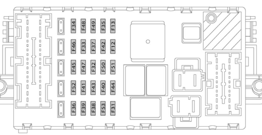
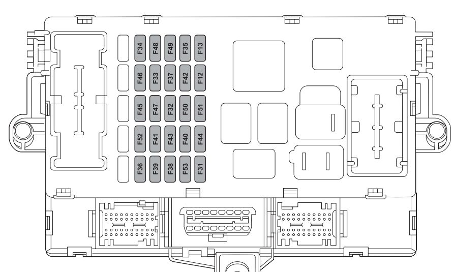
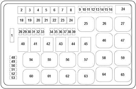
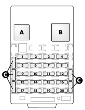
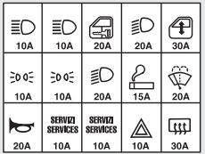
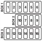
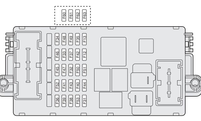
Fuse box on the dashboard
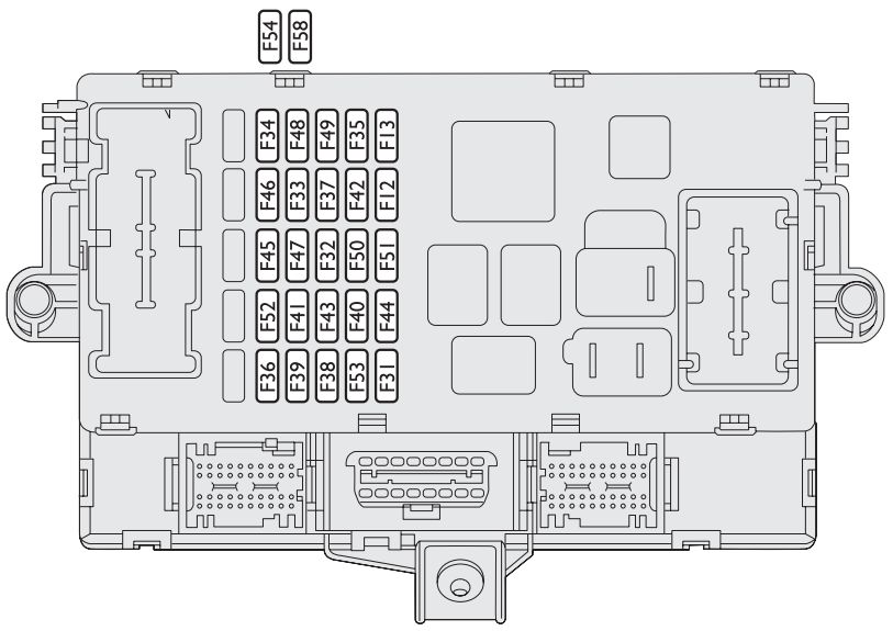
Lancia Musa - fuse box - dashboard
Lancia Musa – fuse box – dashboard
User Fuse Ampere rating [A]
Right-hand dipped beam headlight F12 15
Left-hand dipped beam headlight / headlight aiming device F13 15
Reversing lights / engine compartment control box relay coils / body computer F31 7,5
+30 Driver’s / passenger’s door control units (*) F32 15
Left rear power window F33 20
Right rear power window F34 20
+15 Cruise control, signal from switch on brake pedal for control units (*) F35 7,5
+30 Presetting for trailer control unit, rear locks front locks with single door control unit (*) F36 20
+15 Third brake light, instrument panel, brake lights (*) F37 10
Boot unlocking F38 15
+30 EOBD diagnostic socket, sound system, navigator, tyre pressure control unit (*) F39 10
Rear heated screen F40 30
Heated door electric mirrors F41 7,5
+15 ABS / ESP control unit (*) F42 7,5
Windscreen wiper/washer F43 30
Cigar lighter / current socket on tunnel F44 20
Heated seats F45 15
Boot current socket F46 20
Driver’s door control unit power supply (power window, lock) F47 20
Passenger’s door control unit power supply (power window, lock) F48 20
+15 utilities (left and central dashboard control lights, electric mirrors, heated seat control lighting, presetting for radiotelephone, navigator, rain / daylight sensors, parking sensor control unit, sunroof control lighting) (*) F49 7,5
Airbag control unit F50 7,5
+15 Tyre pressure control unit, ECO / Sport control (*) F51 7,5
Rear screen wiper/washer F52 15
+30 Direction indicators, hazard lights, instrument panel (*) F5 10

(*) +30 = battery directive positive terminal (not under key)

(*) +15 = positive terminal under key

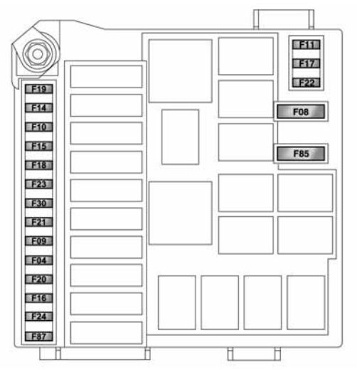
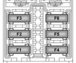
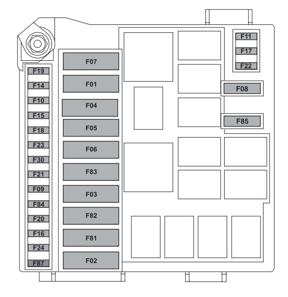
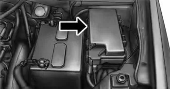
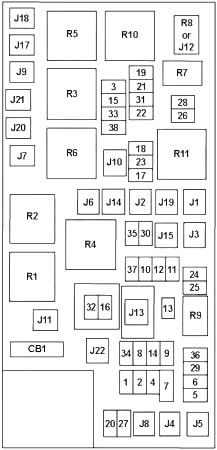
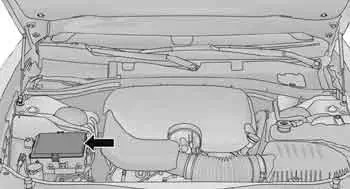
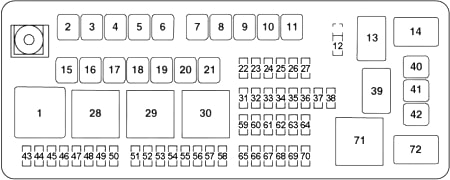
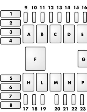
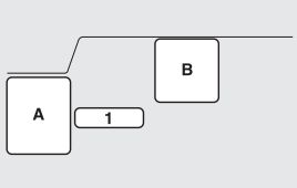
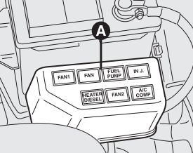
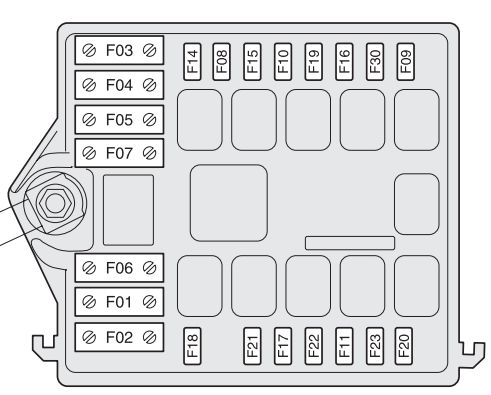
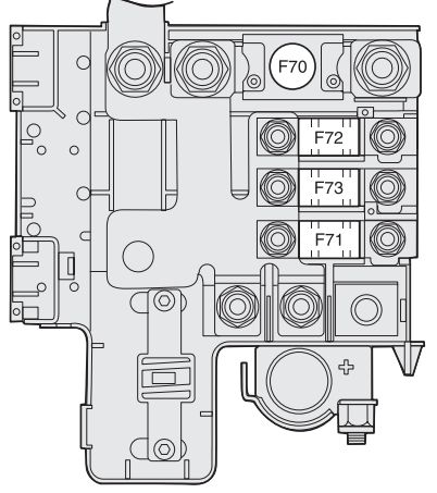
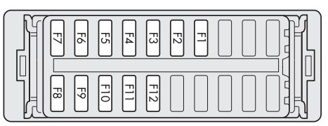
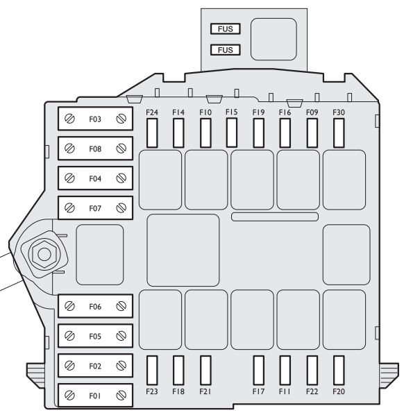
Fuse box near the battery

Lancia Musa - fuse box - engine compartment
Lancia Musa – fuse box – engine compartment
User Fuse Ampere ranting [A]
Dashboard control unit 1 F1 70
Power steering control unit F2 70
Ignition switch F3 20
Dashboard control unit 2 F4 50
ABS / ESP control unit F5 50
Radiator electric fan (low speed) (all versions) F6 30
Radiator electric fan (high speed) (all versions excluded 1.4 16V heated) F7 40
Climate control electric fan F8 30
Headlight washer F9 20
Horn F10 15
Electronic injection secondary services F11 15
Right main beam headlight F14 10
Left main beam headlight F15 10
Electronic injection primary services F17 10
+30 Engine control unit / Radiator electric fan remote control switch (1.9 Multijet) (*) F18 7,5
Compressor F19 7,5
Heated diesel oil filter (Multijet) F20 30
Fuel pump F21 15
Electronic injection primary services (1.4 16V) F22 15
Electronic injection primary services (Multijet) F22 20
Dual FuNction System gearbox oil pump F23 15
Dual FuNction System gearbox fuse box power supply (+ key) F16 7,5
+15 Electric power steering (*) F24 7,5
Front fog lights F30 15

(*) +30 = battery directive positive terminal (not under key)

(*) +15 = positive terminal under key

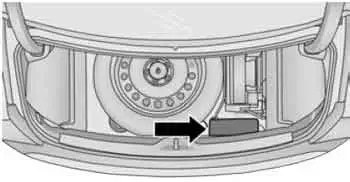
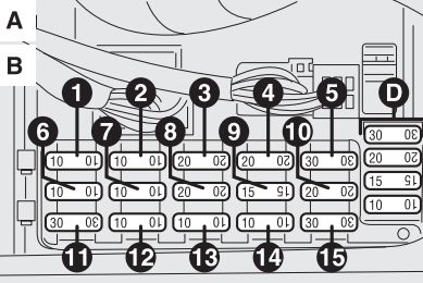
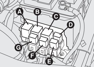
Optional fusebox (on auxiliary bracket)

User Fuse Ampere rating [A]
+30 Outside radio amplifier (*) F34 15
+30 Sunroof (*) F58 20

(*) +30 = battery directive positive terminal (not under key)

(*) +15 = positive terminal under key

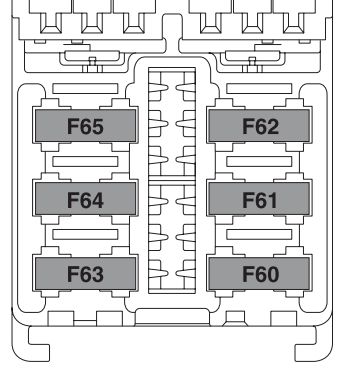
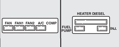
Fuses external to engine compartment fusebox

User Fuse Ampere rating [A]
Dual FuNction System gearbox pump F01 30
Glow plug warming (Multijet) F04 50

(*) +30 = battery directive positive terminal (not under key)

(*) +15 = positive terminal under key

WARNING: Terminal and harness assignments for individual connectors will vary depending on vehicle equipment level, model, and market.

Lancia Delta mk3 (2008 – 2014) – fuse box diagram

Lancia Delta mk3 (2008 – 2014) – fuse box diagram

Year of production: 2008, 2009, 2010, 2011, 2012, 2013, 2014

Dashboard fuse box

Lancia Delta mk3 - fuse box - dashboard
Lancia Delta mk3 – fuse box – dashboard

The fuse box is located in the lower area next to the pedal unit.

Consumer Fuse Ampere rating [A]
Right dipped beam headlight F12 7,5
Right dipped beam headlight (Xenon gas discharge bulb) F12 15
Left dipped beam headlight, headlight alignment corrector F13 7,5
Left dipped beam headlight (Xenon gas discharge bulb) F13 15
Climate control system fan relay coil, body computer F31 5
Spare F32
Left rear electric window F33 20
Right rear electric window F34 20
Reversing lights, engine compartment control unit relay coils, brake light pedal control (normally closed contact), water in the diesel fuel sensor, air flow meter F35 5
Central locking system control unit, fuel butterfly, dead lock, tailgate release F36 20
Third brake light, instrument panel, Adaptive Headlights Node, control unit on left-hand gas discharge headlight F37 7,5
Rear and front courtesy ligths (where fitted), sun visor lights, glove compartment ligtht and luggage compartment light F38 10
Radio, radio-navigator, Blue&Me Node, alarm siren, alarm system on courtesy light, climate control unit, tyre pressure detection control unit, diagnostic connector, rear courtesy light F39 10
Heated rear window F40 30
Electric door mirror demisters, demisters on windscreen jets F41 7,5
Brake Node, yaw sensor F42 5
Windscreen wiper system on steering wheel interface, bi-directional windscreen/rearscreen washer pump system on steering wheel interface F43 30
Cigar lighter/power socket on tunnel, luggage compartment power socket F44 15
Spare F45
Sunroof motor F46 20
Driver-side front electric window F47 20
Passenger-side front electric window F48 20
Emergency, right, left and central control panels on radio/ radio-navigator (illumination), steering wheel controls (illumination), controls on front courtesy light (illumination), volume-sensing alarm control unit, electric sunroof system (controls illumination control unit), rain/dusk sensor, electro-chrome mirror, heated front seats controls F49 5
Air Bag Node F50 7,5
Cigar lighter (illumination), cruise control control, Convergence Node, Parking Sensor Node, AQS sensor, climate control unit, door mirror adjustment, tyre pressure detection control unit, Lane assistance Node, control unit on right-hand gas discharge headlight (*) F51 5/7,5(*)
Rear wiper system on steering wheel interface F52 15
Instrument panel, direction indicators F53 7,5

Engine compartment fuse box

Lancia Delta mk3 - fuse box - engine compartment
Lancia Delta mk3 – fuse box – engine compartment

The fuse box is located on the right side of the engine compartment, next to the battery.

Consumers Fuse Ampere rating [A]
Spare F08
Headlight washer pump F09 20
Horn F10 10
Electronic injection secondary loads F11 10
Main beam headlights F14 15
PTC1 additional heater F15 30
Engine Management Node F16 7,5
Electronic injection primary loads F17 10
Engine Management Node F18 7,5
Air conditioning compressor F19 7,5
Electronic injection primary loads (1.4 engine) F22 15
Electronic injection primary loads (1.8 and diesel engine) F22 20
Brake Node (valves) F23 5
Electric Steering Node F24 5
Fog/cornering lights F30 15
Fuel pump F85 15

Luggage compartment fuse box

Lancia Delta mk3 - fuse box - luggage compartment
Lancia Delta mk3 – fuse box – luggage compartment

The fuse box located on the left side of luggage compartment.

Consumers Fuse Ampere rating [A]
Right front seat adjustment node F1 30
Left front seat adjustment node F2 30
Left front seat heating F3 10
Right front seat heating F6 10
Audio Hi-Fi control unit F4 15
BASSBOX loudspeaker (Hi-Fi system) F5 10

WARNING: Terminal and harness assignments for individual connectors will vary depending on vehicle equipment level, model, and market.

Lancia Ypsilon (from 2011) – fuse box diagram

Lancia Ypsilon (from 2011) – fuse box diagram

Year of production: 2011, 2012, 2013, 2014, 2015, 2016

Engine compartment fuse box

Lancia Ypsilon mk2 - fuse box - engine compartment
Lancia Ypsilon mk2 – fuse box – engine compartment
Description Fuse Ampere rating [A]
BCM F01 60
RDU F02 50
Ignition switch F03 20
BSM1 (pump) F04 40
EPS F05 70
Engine single speed cooling fan (heated engines) F06 20
Engine dual speed cooling fan solenoid valve/Engine cooling fan low speed (conditioned engines) F06 30
Engine cooling electric fan high speed F07 40
Fog lights F08 30
Headlamp washer pump F09 20
Horns F10 15
Engine management system (secondary loads) F11 10
Main beam headlights F14 15
Sunroof motor F15 20
+15 ECM/coil T10 F16 7,5
ECM main loads (versions 0.9 TwinAir 85 HP/1.2 8V 69 HP) F17 10
‘+30 ECM/coil T09 F18 5
Fuel pump F19 15
Heated rear window/mirror defrosters F20 30
Air conditioning compressor F21 7,5
Supply from SCM main relay for ECU (versions 0.9 TwinAir 85 HP/1.3 16V MultiJet) F22 15
Supply from SCM main relay for ECM (versions 1.2 8V 69 HP) F22 20
BSM 9.0 (ECU, valves) F23 20
BSM 9.0/NGE (+15 INT) F24 7,5
Heater plug control unit (versions 1.3 16V MultiJet) F81 60
Passenger compartment fan F82 40
Front power socket (with or without cigar lighter) F85 15
Battery charge status sensor F87 5

+15 = ignition-operated positive terminal

+30 = battery direct positive terminal (not ignition-operated)

Dashboard fuse box

Lancia Ypsilon mk2 - fuse box - dashboard
Lancia Ypsilon mk2 – fuse box – dashboard
Description Fuse Ampere rating [A]
Free F12
+ 15 headlamp alignment corrector and IPC headlamp levelling F13 5
+ 15 INT/A F31 5
Free F32
+30 KL30 F36 10
+15 switch on brake pedal (NO) F37 7,5
Door central locking F38 20
Two-way windscreen washer pump F43 20
Front electric window (driver side) F47 20
Front electric window (passenger side) F48 20
+ 15 KL15 F49 7,5
+ 15 KL15 F50 7,5
+ 15 KL15 F51 5
+30 KL30 F53 7,5

+15 = ignition-operated positive terminal

+30 = battery direct positive terminal (not ignition-operated)

Luggage compartment fuse box

Lancia Ypsilon mk2 - fuse box - luggage compartment
Lancia Ypsilon mk2 – fuse box – luggage compartment
Description Fuse Ampere rating [A]
BOSE HI-FI system F60 20
Free F61
Heated seats F62 15
Rear right electric window F63 20
Rear left electric window F64 20
Alarm setup supply F65 7,5

WARNING: Terminal and harness assignments for individual connectors will vary depending on vehicle equipment level, model, and market.

Lancia Voyager (2008 – 2020) – fuse box diagram

Lancia Voyager (2008 – 2020) – fuse box diagram

Year of production: 2008, 2009, 2010, 2011, 2012, 2013, 2014, 2015, 2016, 2017, 2018, 2019, 2020

Engine compartment fuse box

Lancia Voyager - fuse box - diagram engine compartment
Lancia Voyager – fuse box – diagram engine compartment
Lancia Voyager - fuse box - diagram engine compartment fuse box
Lancia Voyager – fuse box – diagram engine compartment fuse box


No. A Description
1 15 Center High Mounted Stop Light (CHMSL)/Brake Switch
2 20 Trailer Lighting, Front Fog Lamps, Intelligent Battery Sensor (IBS)
3 20 ’12-’20: Front/Rear Axle Locker (’12-’16), Vacuum Pump Motor
4 10 ’08-’15: Trailer Tow
5 25 Inverter
6 20 Power Outlet No.1, Cigar Lighter (Instrument Panel or with Console Rear), Rain Sensor
7 20 Power Outlet No.2
8 20 Front Heated Seat
9 20 Rear Heated Seat
10 20 ’08: Ignition Off Draw – Vehicle Entertainment System, Satellite Digital Audio Receiver (SDARS), DVD, Hands Free Module (HFM), Universal Garage Door Opener, Vanity Lamp
15 ’09-’20: Ignition Off Draw — Vehicle Entertainment System, Satellite Digital Audio Receiver (SDARS), DVD, Hands-Free Module (HFM), Universal Garage Door Opener, Vanity Lamp, Streaming Video Module
11 10 Ignition Off Draw – Air Conditioning/Automatic Temperature Control (HVAC/ATC), MW SENSR, Underhood Lamp
12 30 Amplifier, Radio
13 20 Ignition Off Draw – Cabin Compartment Node (CCN), Wireless Control Module (WCM), Siren, Clock Module, Multifunction Control Switch, Instrument Cluster
14 20 except USA (’08-’11): Trailer Tow
15 20 COL MOD, IR SNS, Heater Ventilation, Air Conditioning/Automatic Temperature Control (HVAC/ATC), Rear View Mirror, Cabin Compartment Node (CCN), Transfer Case Switch, RUN/ST, Multifunction Control Switch, Tire Pressure Monitor (TPM), Glow Plug Module (Diesel), Assy-Shifter (Hall Effect), Acoustic Noise Cancellation (ANC), Instrument Cluster
16 10 Occupant Restraint Controller (ORC), Occupant Classification Module (OCM)
17 15 Left Tail/License/Park Lamp, Running Lamps
18 15 Right Tail/Park/Run Lamp
19 25 Auto Shut Down (ASD No.1 & 2), Powertrain Control Module (PCM)
20 15 Cabin Compartment Node – Interior Light (CNN), Switch Bank, Steering Control Module (SCM), Switch Steering Wheel, Instrument Cluster
21 20 Auto Shut Down (ASD No.3)
22 10 Right Horn
23 10 Left Horn
24 25 Rear Wiper
25 20 Gasoline: Fuel Pump
20 Diesel: Diesel Lift Pump
26 10 Power Mirror Switch, Driver Window Switch
27 10 Ignition Switch, Wireless Control Module, PEM, Steering Column Lock, Keyless Entry Module (’10-)
28 10 Next Generation Controller (NGC), Transmission Feed, Diagnostic Link Connector (J1962 (’08)), Powertrain Control Module (PCM), Transmission Control Module (TCM)
29 10 Occupant Classification Module (OCM)
30 15 ’08-’16: Rear Wiper Module, Power Folding Mirror, Diagnostic Link Connector (J1962 (’09-’11))
15 ’17-’20: Diagnostic Link Connector
31 20 Back-Up Lamps
32 10 Occupant Restraint Controller (ORC), Trailer Tow (Europe)
33 10 Next Generation Controller (NGC), Global Powertrain Engine Controller (GPEC), Transmission Control Module (TCM), Powertrain Control Module (PCM)
34 10 ’08: Park Assist, Heater Ventilation, Air Conditioning Module (HVAC), Headlamp Wash, Compass
10 ’09-’20: Park Assist, Heater Ventilation, Air Conditioning Module (HVAC), Headlamp Wash, Compass, IR Sensor, Rear Camera, Door Lamps,
Flashlight, Lamp Flashlight, Automatic Headlamp Leveling Module (AHLM), Relay Diesel Cabin Heater (Diesel), Radiator Fan (Diesel)
35 10 Heated Mirrors
36 20 Power Outlet No.3 (Instrument Panel or with Console Center)
37 10 Anti-Lock Brake System (ABS), Electronic Stability Program (ESP), Stop Lamp Switch, Fuel Pump Relay (Hi Control)
38 25 Door Lock/Unlock Motors, Liftgate Lock/Unlock Motors
   
J1 40 Power Folding Seat
J2 30 Power Liftgate Module
J3 40 ’08: Rear Door Module
30 ’09-’20: Rear Door Module
J4 25 Driver Door Node
J5 25 Passenger Door Node
J6 40 Anti-Lock Brake System (ABS) Pump, Electronic Stability Control (ESC) Module
J7 30 Anti-Lock Brake System (ABS) Valve, Electronic Stability Control (ESC) Module
J8 40 Power Memory Seat
J9 40 ’08-’16: Partial Zero Emissions Vehicle (PZEV) Motor, Flex Fuel
J10 30 Headlamp Wash Relay, Manual Turning Valve
J11 30 Power Sliding Door Module, Anti–Theft Module Relay Lock Feed
J12 30 ’12-’20: Rear Blower (HVAC), Radiator Fan Motor
J13 60 Ignition Off Draw (IOD) – Main
J14 40 Rear Window Defogger
J15 30 ’08-’10: Rear Blower
30 ’11: Front Blower
40 ’12-’20: Front Blower
J17 40 Starter
J18 20 Powertrain Control Module (PCM) Trans Range
J19 60 Radiator Fan
J20 30 Front Wiper LO/HI
J21 20 Front/Rear Washer
J22 25 Sunroof Module
Circuit Breaker
CB1  –
Relay
R1 Run/Accesory
R2 Ignition Switch (RUN)
R3 Starter
R4 Run/Start
R5 Powertrain Control Module (PCM)
R6 Electrical Back Light (EBL)
Rear Window Defogger
R7 Fuel Pump
R8  –
R9 Rear Blower
R10 Automatic Shut Down (ASD)
R11 Radiator Fan Low


WARNING: Terminal and harness assignments for individual connectors will vary depending on vehicle equipment level, model, and market.

Lancia Thema (2011 – 2022) – fuse box diagram

Lancia Thema (2012 – 2022) – fuse box diagram

Year of production: 2012, 2013, 2014, 2015, 2016, 2017, 2018, 2019, 2020, 2021, 2022

Engine compartment fuse box

Lancia Thema - fuse box diagram - engine comaprtment
Lancia Thema – fuse box diagram – engine comaprtment
Lancia Thema - fuse box diagram - engine comaprtment fuse box
Lancia Thema – fuse box diagram – engine comaprtment fuse box
No. A Description
1  –
2 40 Radiator Fan No.1
50 6.2L (’22), Police (’22): Radiator Fan
3 50 Power Steering No.1, Radiator Fan (except 6.2L (’15-’17))
4 30 Starter
5 40 Anti-Lock Brakes, Electronic Stability Control
6 25 ’13-’14: Anti-Lock Brakes
30 ’15-’22: Electronic Stability Control
7 20 Police (’15-’22): Ignition Run / ACC No.1
50 Thema (Diesel): Cabin Heater No.1
8 20 Police (’15-’20): Ignition Run / ACC No.2
50 6.2L (’18-’20): Radiator Fan
50 Thema (Diesel): Cabin Heater No.2
9 20 All-Wheel Drive Module
10 10 ’11-’13: Security
5 ’14: Security
10 ’15-’22: Security (Intrusion MOD), Under hood Lamp (Police (’15-’22))
11 20 Horns
12 10 Air Conditioning Clutch
13  –
14 25 ’11-’12: Anti-Lock Brakes
15 25 ’11-’13: Transmission Control Module
20 ’15-’22: Left HID Headlamp
16 20 ’15-’22: Right HID Headlamp
18 50 except 6.2L: Radiator Fan No.2
19 50 Power Steering No.2, Radiator Fan (6.2L (’15-’17))
20 30 Wiper Motor
21 30 Headlamp Washers, Police Feed (’15)
20 Police (’16-’22): Bat Feed No.2
22 40 6.2L (’15-’22): Engine Cooling Pump
50 Thema (Diesel): Glow Plug Module
20 Police (’15-’22): Bat Feed No.3
23 20 Police (’15-’22): Bat Feed No.1
30 Thema (Diesel): Fuel Pump Feed, Diesel Fuel Heater
24 20 Police (’15-’22): Ignition Run, ACC Feed No.3
50 Thema (Diesel): Cabin Heater No.3
50 6.2L (’18-’20): Radiator Fan
28 25 ’11-’14: Fuel Pump
29 15 ’11-’14: Transmission Control Module, Shifter
15 Charger Police (’15-’22): Transmission Control Module
30  –
31 25 Engine Module
32  –
33  –
34 25 Powertrain Control Module No.1
35 20 Powertrain Control Module No.2
36 10 Anti-Lock Brake Module, Electronic Stability Control, Steering Column Lock Module (Chrysler 300 – ’19-’22)
37 10 Engine Controller, Rad Fan Relays, Electric Power Steering Module (’15-’22), Fuel Pump Relay (’15-’22), 5–Speed Transmission Control Module (’15-’22)
38 10 Airbag Module
39 10 Power Steering Module, AC Clutch Relay, Vacuum Pump Relay (’15-’22), EHPS (Police), Cabin Heater Relay Coils (Diesel)
48 10 AWD Module, Front Axle Disconnect
10 Thema (Diesel): DTCM/Diesel Scr Module
49 15 Thema: Powertrain Control Module No.3
50  –
51 20 Vacuum Pump
52 5 ’15-’22: Adaptive Cruise
53  –
Relay
25 Vacuum Pump
26  –
27 Starter
40 Front Axle Disconnect
41 Horns
42 Front Wiper No.1
43 A/C Clutch
44 Transmission
45 Front Wiper No.2
46 HID Headlamps – Left
47 Radiator Fan No.1
54 Fuel Pump
55  –
56  –
57 Radiator Fan No.2
58 Radiator Fan No.3
59 Ignition Run/Start
60 Headlamp Washers
61  –
62  –
63 Automatic Shut Down (ASD) No.1
64  –
65 HID Headlamps – Right

Luggage Compartment Fuse Box

Lancia Thema - fuse box diagram - luggage comaprtment
Lancia Thema – fuse box diagram – luggage comaprtment
Lancia Thema - fuse box diagram - luggage comaprtment fuse box
Lancia Thema – fuse box diagram – luggage comaprtment fuse box


No. A Description
2 60 Front PDC Feed #1
3  –
4 60 Front PDC Feed #2
5 30 Sunroof
20 Police (’15-’22): Dome Lamp
6 40 Exterior Lighting #1
7 40 Exterior Lighting #2
8 30 Interior Lighting, Washer Pump (’11-’14)
9 30 ’11-’14: Power Locks
40 ’15-’22: Power Locks
10 30 Driver Door
11 30 Passenger Door
12 20 ’11-’14: Cigar Lighters, Instrument Panel & Power Outlet Console Rear
20 ’15-’22: Dual USB Center Console Rear, Cigar Lighter Instrument Panel, IP APO (’20-‘222)
15 40 HVAC Blower
16 20 Police (’15-’22): Left Spot Lamp
17 20 Police (’18-’22): Right Spot Lamp
18 20 SRT: Active Dampening Module
30 Police (’15-’22): Mod Network Interface (VISM Mod)
19  –
20  –
21 30 6.2L (’15): Fuel Pump
25 Charger STD (’15): Fuel Pump
30 ’16-’22: Fuel Pump (except 6.2L SRT Demon ’18, 6.2L SRT HO – ’19, 6.2L ADR – ’20-’21)
22 20 Police (’15-’17): Right Spot Lamp
20 Thema: Trailer Park Lamp
5 ’18-’22: Cyber Gateway Mod
23 10 Fuel Door, Diagnostic Port
24 15 ’11-’15: Radio Screen (Integrated Center Stack)
10 ’16-’22: Integrated Center Stack
25 10 Tire Pressure Monitor
26 15 ’15-’22: Transmission Control Module (Cygnus Transmission Module), Electronic Shift Module (’15-’19)
25 Thema: Transmission Control Module
27 25 Amplifier
31 25 Power Seats
32 15 HVAC Module, Cluster
33 15 Ignition Switch, Wireless Module, RF Hub Module (’15-’22), Steering Column Lock (’15-’22), Remote Start (’20-’22)
34 10 except Police: Steering Column Module, Clock
35 10 ’11-’14: Battery Sensor
5 ’15-’22: Battery Sensor
36 15 ’15-’22: Electronic Exhaust Valve
20 Thema: Trailer Tow Module Lighting
37 15 ’11-’14: Radio
20 ’15-’22: Radio
38 20 ’11-’14: Power Outlet Inside Arm Rest
15 ’15: Console Power Outlet, Console Media Hub
20 ’16-’19: Power Outlet Inside Arm Rest, Console Media Hub
20 ’20-’22: Media Hub / Console APO
40 30 6.2L: Fuel Pump (SRT Demon – ’18; SRT HO – ’19, ADR – ’20)
41 30 6.2L: Fuel Pump (SRT Demon – ’18; SRT HO – ’19, ADR – ’20)
42 30 Rear Defrost
43 25 ’11-’14: Rear Heated Seats, Steering Wheel Module
20 ’15-’22: Comfort Seat and Steering Wheel Module (Heated Steering Wheel, Rear Heated Seats)
44 10 Park Assist, Blind Spot, Rear View Camera
45 15 Cluster, Rearview Mirror, Compass, Humidity Sensor, Forward Facing Camera (Lane Departure – ’17-’22), Cyber Gateway (’18-’22)
46 10 ’11-’14: Adaptive Cruise Control
47 10 Adaptive Front Lighting, Auto High Beam (’15-’16), Day Time Running Lamps (’15-’22)
48 20 Active Suspension
49  –
50  –
51 20 Front Heated Seats, Front Ventilated Seats (’17-’22)
52 10 Heated Cupholders, Rear Heated Seat Switches
53 10 HVAC Module, In Car Temperature Sensor
54  –
55  –
56  –
57  –
58 10 Airbag Module
59 20 Police (’15-’22): Adjustable Pedals
60 5 ’15-’16: Heated Washer Nozzles
61 20 Thema: Trailer Tow
62  –
63  –
64 25 Rear Windows
65 10 Airbag Module
66  –
67 15 ’11-’14: Run Sense, Front Door Illumination
10 ’15-’22: Rain and Light Sensor, Sunroof, Inside Rear View Mirror, Power Outlet Illumination (Center Console), Police Run Acc Relay
68 15 ’11-’14: Illumination, Rear Sunshade
10 ’15-’22: Dual USB Power Outlet – R/A Sense, Rear Sunshade, Rear USB Timer (’17-’22)
69  –
70  –
Relay
1 Ignition Run
13  –
14  –
28 Rear Defrost
29 Rear Windows, Run Sense, Rear Sunshade
30 Cigar Lighters
39  –
71 Hvac Blower
72 Fuel Pump

WARNING: Terminal and harness assignments for individual connectors will vary depending on vehicle equipment level, model, and market.

Lancia Flavia 2nd Generation (2012 – 2014) – fuse box diagram

Lancia Flavia 2nd Generation (2012 – 2014) – fuse box diagram

Year of production: 2012, 2013, 2014

Fuses – integrated power module

The Integrated Power Module is located in the engine compartment near the air cleaner assembly.

Cavity Cartfidge fuse Mini Fuse Description
1 40 Amp Green Power Top Module
2 20 Amp Yellow Brake Vacuum Pump
3 10 Amp Red Center High Mounted Stop Light (CHMSL)/ Brake Switch
4 10 Amp Red Ignition Switch
5 20 Amp Yellow Trailer Tow (when present)
6 10 Amp Red Power Mirror Switch/Climate Controls
7 30 Amp Green Ignition Off Draw (IOD) Sense 1
8 30 Amp Green Ignition Off Draw (IOD) Sense 2
9 40 Amp Green Battery Feed – Power Seats (for versions/ markets, where provided)
10 20 Amp Yellow Instrument Panel/Power Locks/Interior Lights
11 15 Amp Lt Blue Selectable Power Outlet (Inside Center Arm Rest)
12 20 Amp Yellow
13 20 Amp Yellow Ignition/Cigar Lighter
14 10 Amp Red Instrument Panel
15 40 Amp Green Radiator Fan Relay
16 15 Amp Lt Blue Sunroof (for versions/markets, where pro- vided)
17 10 Amp Red Wireless Control Module (WCM)/Clock/ Steering Control Module (SCM)
18 40 Amp Green Auto Shutdown (ASD) Relay
19 20 Amp Yellow Audio Amplifier (for versions/markets, where provided)
20 15 Amp Lt. Blue Radio
21 10 Amp Red Siren (for versions/markets, where provided)
22 10 Amp Red Ignition Run – Climate Controls/Hot Cupholder (for versions/markets, where provided)
23 15 Amp Lt. Blue Auto Shutdown (ASD) Relay 3
24 25 Amp Natural Sunroof (for versions/markets, where pro- vided)
25 10 Amp Red Ignition Run — Heated Mirrors (for versions/markets, where provided)
26 15 Amp Lt. Blue Auto Shutdown (ASD) Relay 2
27 10 Amp Red Ignition Run – Occupant Classification Module (OCM)/Occupant Restraint Controller (ORC)
28 10 Amp Red Ignition Run — Occupant Classification Module (OCM)/Occupant Restraint Controller (ORC)
29 Hot Car (No Fuse Required)
30 20 Amp Yellow Ignition Run – Heated Seats (for versions/ markets, where provided)
31 10 Amp Red Headlamp Washer (for versions/markets, where provided)
32 30 Amp Pink Auto Shutdown (ASD) Relay 1
33 10 Amp Red Switch Bank/Diagnostic Link Connector/ Powertrain Control Module (PCM)
34 30 Amp Pink Anti-Lock Brakes (ABS) Module (for versions/markets, where provided)/ Electronic Stability Control (ESC) Module (for versions/markets, where provided)
35 40 Amp Green Anti-Lock Brakes (ABS) Module (for versions/markets, where provided)/ Electronic Stability Control (ESC) Module (for versions/markets, where provided)
36 30 Amp Pink Passenger Door Module (PDM)/Driver Door Module (DDM)
37 25 Amp Natural Power Top Module (for versions/markets, where provided)

WARNING: Terminal and harness assignments for individual connectors will vary depending on vehicle equipment level, model, and market.

Alfa Romeo 166 FL (2003 – 2007) – fuse box diagram

Alfa Romeo 166 FL (2003 – 2007) – fuse box diagram

Year of production: 2003, 2004, 2005, 2006, 2007

Fuses and relays in the control unit

Alfa Romeo 166 - fuse box - control unit
Alfa Romeo 166 – fuse box – control unit

The fuses for the main devices are housed in a control unit under the dashboard, to the left of the steering column.

Fuses and relays in engine compartment

Alfa Romeo 166 - fuse box - engine bay
Alfa Romeo 166 – fuse box – engine bay
Relays Description
A Dipped beam headlight
B Climate control fan
C Horn
D Front fog light
F Petrol versions (single fan): engine cooling radiator (high speed)
JTD versions (two-fan): engine cooling radiator (high speed
G Conditioner compressor
H Petrol versions: engine cooling radiator (low speed)
JTD versions (two-fan): engine cooling radiator (high speed)
L . Fuel pump
M Electronic injection main relay
N Starter motor
P Diesel filter warming (JTD versions)
JTD versions (two-fan): engine cooling radiator (low speed)


Fuses and relays in the boot

Alfa Romeo 166 - fuse box - boot
Alfa Romeo 166 – fuse box – boot
Relays Description
A Air mixing actuator, climate control unit, additional heater control (JTD versions)
B Rearscreen heating relay
C Seat warming control, electrochromic driving mirror, sun visor light, rain sensor, parking sensor control unit, door mirror control light, remote control receiver, alarm system control unit, driver’s power window control LOCK warning light
D Windscreen heating, door mirror defrosting
E Front seat warming, rear current socket, front seat electric adjustment, powered sunroof
F Direction indicators, trailer presetting


Fuse table summary

External lights Fuse Ampere rating [A] Location
Brake lights (switch) 9 5 86
1 15 86
Direction indicators 12 10 93
External lights (control) 5 10 86
Front fog lights 16 15 89
Headlights and headlight position sensor (gas discharge headlights) 6 7,5 86
IGE control unit:
– brake light switch 1 15 86
– brake lights 9 5 86
– headlight spot 11 15 86
– left side lights 17 10 86
– rear light units 15 10 86
– right side lights 8 10 86
Left dipped beam headlight 12 15 89
Reversing lights (only versions with manual gearbox) 13 10 86
Right dipped beam headlight 10 15 89


Internal lights Fuse Ampere rating [A] Location
Dashboard light dimmer 5 10 86
Door mirror control light 15 10 93
Glovebox light 5 10 86
Seat warming control light 15 10 93
Sun visor lights 15 10 93


System/component Fuse Ampere rating[A] Location
ABI control unit 13 10 86
ABI control unit – Central locking 19 20 93
ABI control unit – Front LH power window 18 20 93
ABI control unit – Front RH power window 3 20 93
ABI control unit – Rear LH power window 14 20 93
ABI control unit – Rear RH power window 17 20 93
ABS control unit 9 5 86
7 40 89
3 40 89
Additional heater (JTD versions) 17 20 89
13 10 93
Alarm system (control unit) 12 10 93
15 10 93
Alfa Romeo Code System 20 5 86
16 5 86
Cell phone (handset) 18 5 86
5 10 86
Central locking (ABI control unit) 19 20 93
Cigar lighter 7 20 86
Climate control fan 2 30 89
Climate control unit 19 5 86
Conditioner compressor 13 7,5 89
Cruise Control 5 10 86
Diesel fuel filter warming (JTD versions) 23 30 89
5 40 89
Door mirror defrosting 2 7,5 93
Electrochromic driving mirror 15 10 93
Electronic injection control unit 20 10 89
21 15 89
22 20 89
Electronic injection system 16 5 86
Engine control unit 18 7,5 89
Engine cooling control unit 16 5 86
Engine cooling radiator fan 4 60 89
Engine cooling radiator fan 5 40 89
EOBD system (socket) 18 5 86
Front LH power window (ABI control unit) 18 20 93
Front RH power window (ABI control unit) 3 20 93
Front LH seat electric adjustment 6 30 93
Front RH seat electric adjustment 5 30 93
Front LH seat warming 9 10 93
Front RH seat warming 8 10 93
Fuel pump 19 15 89
Fuel pump relay coil (engine bay box) 16 5 86
Glow plug (JTD versions) 8 60 89
Headlight washer (intermittent) 12 20 86
Horns 11 15 89
I.C.S. system 5 10 86
6 7,5 86
7 20 86
18 5 86
Instrument panel 6 7,5 86
18 5 86
Navigator 18 5 86
Parking sensors (control unit) 15 10 93
Power windows (driver’s control LOCK warning light) 15 10 93
Powered sunroof 10 20 93
Presetting 4 93
11 93
Rain sensor 15 10 93
Rear current socket 16 20 93
Rear LH power window (ABI control unit) 14 20 93
Rear RH power window (ABI control unit) 17 20 93
Rearscreen heating 1 30 93
Relay coil T21, T22, T23 (boot box 3 5 86
Relay coil T24 (boot box) 5 10 86
Remote control receive 15 10 93
Sound amplifier 20 25 93
Sound system 4 15 86
Sound system controls on steering whee 5 10 86
Starter motor 1 30 89
Trailer presetting 12 10 93
Windscreen heating 7 15 93
Windscreen wiper 14 25 86


WARNING: Terminal and harness assignments for individual connectors will vary depending on vehicle equipment level, model, and market.

Alfa Romeo 156 (2003 – 2006) – fuse box diagram

Alfa Romeo 156 (2003 – 2006) – fuse box diagram

Year of production: 2003, 2004, 2005, 2006

Fuse and relays in the main fusebox

Alfa Romeo 156 FL - main fuse box
Alfa Romeo 156 FL – main fuse box
Relay Description
A Dipped beam light relay
B Relay for sunroof , seat heater, rear window power control, seat electric adjustment
Alfa Romeo 156 FL - main fuse box - symbols
Alfa Romeo 156 FL – main fuse box – symbols

Fuses above the main fusebox

Alfa Romeo 156 FL - above main fuse box
Alfa Romeo 156 FL – above main fuse box

Fuses and relays accessible from the glovebox

Alfa Romeo 156 FL - fuse box - glovebox
Alfa Romeo 156 FL – fuse box – glovebox

Fuse and relays in engine bay

Alfa Romeo 156 FL - fuse box - engine bay - relay
Alfa Romeo 156 FL – fuse box – engine bay – relay
Alfa Romeo 156 FL - fuse box - engine bay relay
Alfa Romeo 156 FL – fuse box – engine bay relay
Relay Description
A Engine radiator cooling fan 2nd speed relay (T.SPARK versions)
B Engine radiator cooling fan 1st speed relay
C Fuel pump relay
D Electronic injection relay
E Climate control compressor relay
F Timing variator relay (1.6 T.SPARK only) or engine radiator fan 2nd speed relay (only 2.5 V6 24V, JTD and JTD 16V Multijet versions)
G Fuel oil heater relay (only Diesel versions)


For JTD 20v Multijet version

Alfa Romeo 156 FL - fuse box - engine bay - relay (JTD version)
Alfa Romeo 156 FL – fuse box – engine bay – relay (JTD version)

For Diesel versions, depending on the options installed, there is a second bracket fastened to the engine compartment rear bulkhead for the following fuses.

Alfa Romeo 156 FL - fuse box - engine bay - relay (diesel)
Alfa Romeo 156 FL – fuse box – engine bay – relay (diesel)
Relay Description
A MAXI-FUSE 30A Additional passenger compartment heater 2nd level relay
B MAXI-FUSE 30A Additional passenger compartment heater 1st level relay


Fuse summary table

Lights Fuse Ampere rating [A] Location
Left front side light 7 10 Main fusebox
Right front side light 6 10 Main fusebox
Left rear side light 6 10 Main fusebox
Right rear side light 7 10 Main fusebox
Left dipped-beam headlamp/Xenon lamps (optional) 8 20 Main fusebox
Right dipped-beam headlamp/Xenon lamps (optional) 4 20 Main fusebox
Left main-beam headlamp 2 20 Main fusebox
Right main-beam headlamp 1 10 Main fusebox
Cruise Control (optional) 13 10 Main fusebox
Left number plate light 7 10 Main fusebox
Right number plate light 6 10 Main fusebox
Reversing lights/Sound system 13 10 Main fusebox
Left rear fog guard 7 10 Main fusebox
Right rear fog guard 6 10 Main fusebox
Direction indicators – Hazard warning lights 14 10 Main fusebox
Fog lamps 16 15 Above main fusebox
Car interior and glovebox lights 12 – 13 10 Main fusebox
HI-FI BOSE system 9 25 Above main fusebox


Services Fuse Ampere rating [A] Location
Windscreen wiper, windscreen washer/Rearscreen wiper/Rain sensor (optional) 10 20 69
Horns 11 20 69
GSM Box for Connect/Navigator-electronic warning system 13 10 69
Front power windows 5 30 69
Left rear power window 4 20 71
Right rear power window 5 20 71
Door locking system – Boot light 3 20 69
Boot electric opening 7 30 71
Rearscreen heating 15 30 69
Wing mirror adjustment 13 10 69
Wing mirror defrosting 15 30 69
Cigar lighter/Odour sensor 9 15 69
Headlamp washer 1 20 72
Headlamp aiming device 4 10 69
Instrument cluster 12 10 69
Main-beam headlamp warning light 2 10 69
Rearscreen heating warning light 15 30 69
Sound system/Diagnosis socket 12 10 69
Electronic alarm system 12 10 69
Supplementary electrical socket in the boot (Sportwagon versions) 10 20 71
Remote control 13 10 69
Controls lighting/Stop lights 3 10 71
Rear control lighting from sidelights 6 10 71
Seat heating/Sunroof/Seat electrical adjustment 8 30 71
Air bag system 2(*) 10(*) 71
ABS system 9 60 68
11(*) 10(*) 71
Alfa Romeo CODE system 13 7,5 71
Climate control system 9 15 69
Engine cooling radiator fan:
First speed:
–  T.SPARK and JTS versions 6 50 68
–  diesel versions 6 60 68
– 2.5 V6 24V versions 6 40 68
Second speed
– T.SPARK and JTS versions 7 30 68
– diesel versions 7 40 68
– 2.5 V6 24V versions 7 40 68
Passenger compartment fan (petrol versions) 1 40 68
Passenger compartment fan (diesel versions) 4 40 68
Electronic ignition and injection system 13 7,5 71
14 15 71
15 15 71
5 30 68
Glow plugs and resistances on fuel oil filter (diesel versions) 8 70 68
Fuel oil heater (JTD versions, JTD 16V Multijet) H 25 74
Services switched off with starting 1 7,5 71
Battery power supply for Alfa Romeo CODE/Injection system 12 7,5 71
(+15) key-controlled service supply (ignition switch) 2 30 68
General service supply (petrol versions) 4 80 68
General service supply (diesel versions) 1 80 68
General service supply 3 70 68
Additional heater (diesel version only) 10 70 68
Oil pump supply (Selespeed versions only) 10 30 68
Selespeed gearbox (2.0 JTS version) 7 30 68
8 20 68
Automatic gearbox (2.5 V6 24V version) 7 40 68
8 20 68

WARNING: Terminal and harness assignments for individual connectors will vary depending on vehicle equipment level, model, and market.

Alfa Romeo GT (2004 – 2010) – fuse box diagram

Alfa Romeo GT (2004 – 2010) – fuse box diagram

Year of production: 2004, 2005, 2006, 2007, 2008, 2009, 2010

Fuse box on dashboard

Alfa Romeo GT - fuse box - dashboard
Alfa Romeo GT – fuse box – dashboard

Fuse box next to battery

Alfa Romeo GT - fuse box - battery
Alfa Romeo GT – fuse box – battery

Fuse box on battery positive pole

Alfa Romeo GT - fuse box - battery (positive pole)
Alfa Romeo GT – fuse box – battery (positive pole)

Fuse summary table

Lights Location Fuse Ampere rating [A]
Hazard warning light Dashboard F53 10
Right dipped-beam headlight Dashboard F12 10
Left dipped-beam headlight Dashboard F13 10
Right main-beam headlight Battery F14 10
Left main-beam headlight Battery F15 15
Foglight Battery F30 15
Braking light Dashboard F37 10
Reversing light Dashboard F35 7,5
+30 direction indicators Dashboard F53 10


Services Figure Fuse Ampere rating [A]
Selespeed transmission pump Battery (positive pole)  F03 (MAXI-FUSE) 30
Additional heater Battery (positive pole) F03 (MAXI-FUSE) 30
Headlight aiming device Dashboard F13 10
Climate control system Dashboard F31 7,5
Climate control system Dashboard F39 15
Climate control compressor Battery F1 7,5
Heater unit relay coils Dashboard F31 7,5
Key-operated +30 Dashboard F32 15
Selespeed transmission Battery F11 15
Selespeed transmission Dashboard F51 7,5
Radio Dashboard F39 15
Navigator Dashboard F39 15
Rearscreen heating Dashboard F40 30
Windscreen – rearscreen washer (pump) Dashboard F43 30
Cigar lighter Dashboard F44 20
Seats with electric heating Dashboard F45 15
Heated wing mirrors – heated nozzles Dashboard F51 7,5
Cruise control Dashboard F35 7,5
Central door locking Dashboard F38 20
Headlight washer Battery F5 20
Services + 30 Dashboard F39 15
Primary services (electronic injection) Battery F8 7,5
Secondary services (electronic injection) Battery F9 15
Secondary services Dashboard F49 7,5
Volumetric sensors Dashboard F39 15
ESP system sensor Dashboard F42 7,5
Steering angle sensor Dashboard F42 7,5
EOBD system diagnosis socket Dashboard F39 15
Cell phone provision Dashboard F39 15
Driver’s door control unit supply Dashboard F47 20
Passenger’s door control unit supply Dashboard F48 20
Controls lighting Dashboard F49 7,5
Climate control system controls lighting Dashboard F35 7,5
Instrument cluster Dashboard F37 10
Instrument cluster Dashboard F53 10
Driver’s door control unit Dashboard F39 15
ABS control unit Dashboard F42 7,5
ABS control unit Battery (positive pole) F04 (MAXI-FUSE) 50
Dashboard control box Battery (positive pole) F02 (MAXI-FUSE) 50
Air – bag control unit Dashboard F50 7,5
Electronic injection control unit +30 Battery F18 7,5
Engine compartment control box (petrol versions) Battery (positive pole) F70 (MEGA-FUSE) 125
Dashboard control unit Battery (positive pole) F71 (MAXI-FUSE 70
Trailer control unit Dashboard F36 10
Climate control fan Battery (positive pole) F05 (MAXI-FUSE) 40
Radiator fan (first speed – petrol versions) Battery (positive pole) F06 (MAXI-FUSE) 40
Radiator fan (second speed – petrol versions) Battery (positive pole) F07 (MAXI-FUSE) 40
Horn Battery (positive pole) F10 15
Fuel pump Battery F21 15
Injectors (petrol versions) Battery F22 15
Ignition coils Battery F21 15
Tailgate electric unlocking Dashboard F60(*) 25
Electronic injection system Battery F16 7,5
Bose system Dashboard F61(*) 15
Bose system Dashboard F62(*) 15
Additional heater Battery F08 30
Ignition switch Battery (positive pole) F72 (MAXI-FUSE) 30
Glow plug warming (JTD versions) Battery F01 (MAXI-FUSE) 50
Heated fuel oil filter (JTD versions) Battery F20 20
Engine compartment control box (JTD versions) Battery (positive pole) F70 (MEGA-FUSE) 150
Radiator fan (first speed – JTD versions) Battery F06 (MAXI-FUSE) 40
Radiator fan (second speed – JTD versions) Battery F07 (MAXI-FUSE) 60
Injectors (JTD versions) Battery F22 20

(*) Fuse behind dashboard control box on an auxiliary bracket

WARNING: Terminal and harness assignments for individual connectors will vary depending on vehicle equipment level, model, and market.

Alfa Romeo 147 FL (2005 – 2010) – fuse box diagram

Alfa Romeo 147 FL (2005 – 2010) – fuse box diagram

Year of production: 2005, 2006, 2007, 2008, 2009, 2010

Fuse box on dashboard

Alfa Romeo 147 - fuse box - dashboard
Alfa Romeo 147 – fuse box – dashboard

Fuse box next to battery

Alfa Romeo 147 - fuse box - battery
Alfa Romeo 147 – fuse box – battery

Fuse box on battery positive pole

Alfa Romeo 147 - fuse box - battery (positive pole)
Alfa Romeo 147 – fuse box – battery (positive pole)

Fuse summary table

Lights Location Fuse Ampere rating [A]
Hazard warning light Dashboard F53 10
Right dipped-beam headlight Dashboard F12 10
Left dipped-beam headlight Dashboard F13 10
Main-beam headlight Battery F2 15
Foglight Battery F30 15
Braking light Dashboard F37 10
Reversing light Dashboard F35 7,5
+30 direction indicators Dashboard F53 10


Services Figure Fuse Ampere rating [A]
Selespeed transmission pump Battery (positive pole) 30
Ignition switch Battery (positive pole) IGN (MAXI-FUSE) 30
Headlight aiming device Dashboard F13 10
Climate control system Dashboard F31 7,5
Climate control system Dashboard F39 15
Climate control compressor Battery F1 7,5
Heater unit relay coils Dashboard F31 7,5
Key-operated +30 Dashboard F32 15
Selespeed transmission Battery F11 15
Selespeed transmission Dashboard F51 7,5
Radio Dashboard F39 15
Navigator Dashboard F39 15
Rearscreen wiper Dashboard F52 15
Left rear power window Dashboard F33 20
Right rear power window Dashboard F34 20
Rearscreen heating Dashboard F40 30
Windscreen – rearscreen washer (two-way pump) Dashboard F43 30
Cigar lighter Dashboard F44 20
Seats with electric heating Dashboard F45 15
Heated wing mirrors – heated nozzles Dashboard F51 7,5
Cruise control Dashboard F35 7,5
Central door locking Dashboard F38 20
Headlight washer Battery F5 20
Services + 30 Dashboard F39 15
Primary services (electronic injection) Battery F8 7,5
Secondary services (electronic injection) Battery F9 15
Secondary services Dashboard F49 7,5
Volumetric sensors Dashboard F39 15
VDC system sensor Dashboard F42 7,5
Steering angle sensor Dashboard F42 7,5
EOBD system diagnosis socket Dashboard F39 15
Cell phone provision Dashboard F39 15
Driver’s door control unit supply Dashboard F47 20
Passenger’s door control unit supply Dashboard F48 20
Controls lighting Dashboard F49 7,5
Climate control system controls lighting Dashboard F35 7,5
Instrument cluster Dashboard F37 10
Instrument cluster Dashboard F53 10
Driver’s door control unit Dashboard F39 15
ABS control unit Dashboard F42 7,5
ABS control unit Battery (positive pole) ABS (MAXI-FUSE) 50
Dashboard control box Battery (positive pole) CPL2 (MAXI-FUSE) 50
Boot control unit Dashboard F39 15
Air – bag control unit Dashboard F50 7,5
Electronic injection control unit +30 Battery F6 7,5
Dashboard control unit Battery (positive pole) CPL1 (MAXI-FUSE) 70
Climate control fan Battery (positive pole) A/C (MAXI-FUSE) 40
Radiator fan Battery (positive pole) FAN1 (MAXI-FUSE) 40
Radiator fan Battery (positive pole) FAN2 (MAXI-FUSE) 40
Horn Battery (positive pole) F3 15
Fuel pump Battery F4 15
Tailgate electric unlocking Dashboard F60(*) 25
Electronic injection system Battery F11 7,5
Bose system Dashboard F61(*) 25
Bose system Dashboard F62(*) 15
Sunroof Dashboard F63(*) 20
Sun roof Dashboard F46 15
Petrol/ignition coil injectors Battery F10 15
Services Battery F12 7,5
Electronic injection Battery (positive pole) EFI (MAXI-FUSE) 30
Engine compartment fuse carrier module Battery (positive pole) JB3 (MAXI-FUSE) 50

(*) Fuse behind dashboard control box on an auxiliary bracket

WARNING: Terminal and harness assignments for individual connectors will vary depending on vehicle equipment level, model, and market.