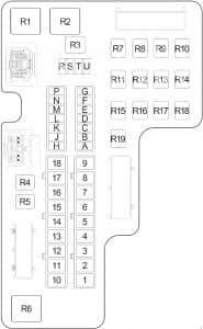
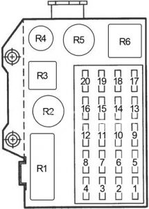
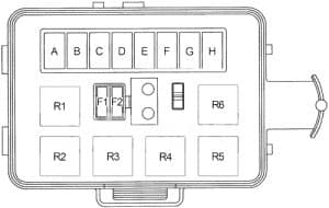
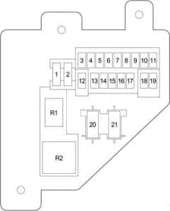
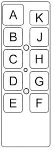
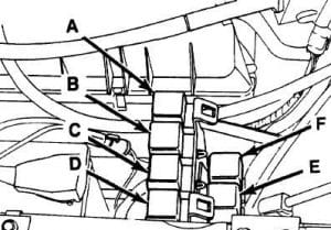
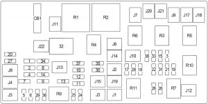
Chevrolet Camaro (1988 – 1992) – fuse box diagram

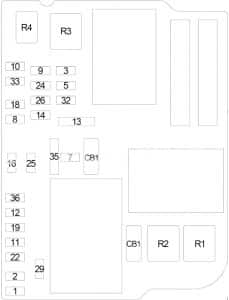
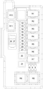
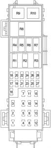
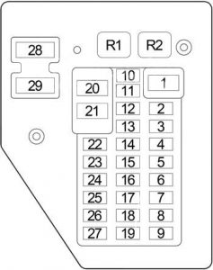
Chevrolet Camaro (1988 – 1992) – fuse box diagram

Year of production: 1988, 1989, 1990, 1991, 1992

Fuse Box diagram

Chevrolet Camaro - fuse box diagram
Chevrolet Camaro – fuse box diagram
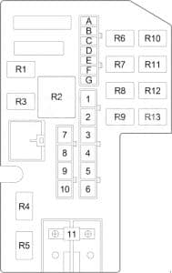
No. A Circuit Protected
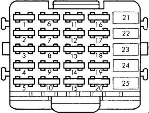
1 10 Engine Control Module
2 10 Fuel Injector Feed No. 1
20 ’88-’89 (Camaro): Engine Cooling Fan
10 ’88-’89 (Firebird): Fuel Pump, Oil Pressure Switch, Electric Cluster
3 15 ’90-’92: Hatch Pull-Down Motor
3 ’88-’89: Crank Signal to E.C.M.
4 20 Cooling Fan Relay
5 20 Turn Signal Lights, Back-Up Lights
6 10 ’90-’92: Fuel Injector Feed No. 2
10 ’88-’89 (Camaro): Fuel Injector
20 ’88-’89 (Firebird): Fuel Injector
7 20 Parking Lights, Side Marker Lights, Taillights
8 25 Heater or Air Conditioner
9 10 Gauges, Audio Alarm System, Vehicle Speed Sensor, TCC Brake Switch, Rear Window Defogger, Daytime Running Lights, Cruise Control, A/C Relay
10 10 ’90-’92: Supplemental Inflatable Restraint
10 ’88-’89 (Camaro): Fuel Pump, Fuel Injector
20 ’88-’89 (Firebird): Fuel Injector
11 20 Glove Box Light, Cigarette Lighter, Hatchback Lid Release, Horn Relay, Interior Lights, Power Antenna, Power Door Locks, Radio/Digital Clock, Computer Command Control
13 5 Instrument Panel Lights
14 10 Radio
16 25 Windshield Wiper/Washer
17 20 Stoplight Switch, Hazard Flasher, Chime
18 10 ’90-’92: VATS II Security Light
19 20 ’90-’92: Radio
20 3 ’90-’92: ECM Crank Circuit
21 10 ’90-’92: Daytime Running Lights
Circuit Breaker
12 35 ’88-’90: Power Windows, Rear Wiper/Washer
30 ’91-’92: Power Windows
15 35 ’88-’90: Power Door Locks, Power Seats, Rear Window Defogger
30 ’91-’92: Power Door Locks, Power Seats, Rear Window Defogger
22 30 ’90-’92: Fog Light

WARNING: Terminal and harness assignments for individual connectors will vary depending on vehicle equipment level, model, and market.

Chevrolet Camaro (2010 – 2015) – fuse box diagram

Chevrolet Camaro (2010 – 2015) – fuse box diagram

Year of production: 2010, 2011, 2012, 2013, 2014, 2015

Passenger compartment fuse box

Chevrolet Camaro - fuse box diagram - fuse box diagram
Chevrolet Camaro – fuse box diagram – passenger compartment
No.
A
Protected Component
1 5 Ignition Switch
2 7.5 Data Link Connector
3 10 Inflatable Restraint Sensing and Diagnostic Module
4 10 Instrument Cluster, Auxiliary Gauge Module
5 15 HVAC Control Module
6 20 Body Control Module
7 25 Circuit Breaker: Seat Adjuster Switch (Passenger)
8 30 Fuse: “13”, “14”
9  –
10  –
11  –
12  –
13 10 Multimedia Player Interface Module, Radio/HVAC Controls, Head-Up Display
14 7.5 Telematics Communication Interface Control Module, Mobile Telephone Control Module
15 30 Body Control Module
16 30 Body Control Module
17 20 Power Outlet – Center Console
18 20 Power Outlet – Center Console Compartment
19 2 Steering Wheel Controls Switch (Left/Right)
20  –
21  –
22  –
23 10 Rear Compartment Lid Release Relay
24 5 Passenger Presence Detection Module
25 20 Body Control Module
26 25 Circuit Breaker: Seat Adjuster Switch (Driver)
27 30 Body Control Module
28 40 ’12-’15: Blower Motor Control Module
29 25 Body Control Module
30 20 Body Control Module
Relay
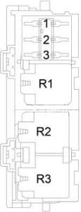
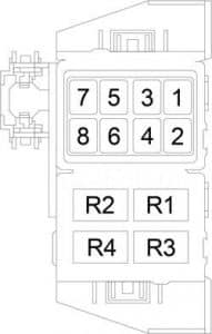
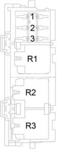
R1 Power Outlet
R2  –
R3 Rear Compartment Lid Release

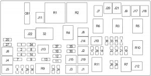
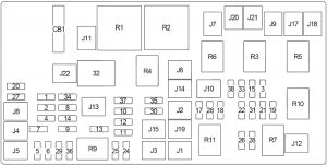
Engine Compartment Fuse Box

Chevrolet Camaro - fuse box diagram - engine compartment
Chevrolet Camaro – fuse box diagram – engine compartment
No.
A
Protected Component
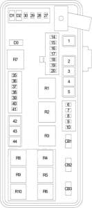
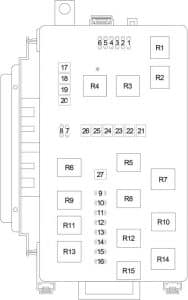
1 10 A/C Compressor Clutch Relay
2 15 Transmission Control Module (Control Solenoid Valve Assembly)
3 10 Intercooler Coolant Pump
4 15 Headlamp Washer Pump Relay
5 15 Engine Control Module
6 30 Windshield Wiper Relay, Windshield Wiper Speed Control Relay
7 10 Camshaft Position (CMP) Actuator Solenoid Valve (3.6L), Evaporative Emission (EVAP) Purge Solenoid Valve (3.6L), Heated Oxygen Sensors
8 10 Heated Oxygen Sensors
9 20 3.6L: Engine Control Module
20 6.2L (SS): Fuel Injector: 2, 4, 6, 8, Ignition Coil: 2, 4, 6, 8
10 20 3.6L: Engine Control Module
20 6.2L (SS): Fuel Injector: 1, 3, 5, 7, Ignition Coil: 1, 3, 5, 7
11 10 Cooling Fan Speed Control Relay, Cooling Fan High Speed Relay, Cooling fan Low Speed Relay
12 30 Starter Relay
13  –
14 7.5 Fuel Pump Control Module, Mass Air Flow/Intake Air Temperature Sensor, Reverse Inhibit Solenoid Actuator, Skip Shift Solenoid Actuator, Valve Lifter Oil Manifold Assembly (6.2L (SS – L99)), Vehicle Speed Sensor
15 5 Instrument Cluster
16 5 HVAC Control Module
17 5 Inflatable Restraint Sensing and Diagnostic Module
18 10 Passenger Air Bag Disable Indicator, Inside Rearview Mirror
19 20 Transmission Control Module (Control Solenoid Valve Assembly)
20 15 Engine Control Module
21 10 ’13-: Charge Air Cooler Coolant Pump
22 20 Brake Booster Pump Motor Relay
23  –
24  –
25 30 Convertible: Power Window (Rear)
26 30 Power Window
27 40 Rear Window Defogger
28  –
29  –
30  –
31 7.5 Outside Rearview Mirror Switch
32 10 Evaporative Emission (EVAP) Vent Solenoid Valve
33 20 Body Control Module
34 25 Sunroof Control Module
35 25 Seat Heating Control Module
36  –
37  –
38 15 Windshield Washer Pump
39 5 Headlamp Leveling Control Module
40 25 ABS Valve – Electronic Brake Control Module (EBCM)
41 30 Cooling Fan High Speed Relay
42 40 ’10-’11: Blower Motor Control Module
43 40 ABS Pump – Electronic Brake Control Module (EBCM)
44 30 Cooling Fan Low Speed Relay
45  –
46 20 Headlamp Ballast (Left)
47 20 Headlamp Ballast (Right)
48  –
49  –
50 15 Front Fog Lamp
51 15 Horn
52  –
53  –
54  –
55 10 Right Headlamp (High Beam)
56 10 Left Headlamp (High Beam)
57  –
58  –
59  –
60  –
61 7.5 Door Mirror Defogger
62  –
63  –
64  –
65  –
66 7.5 Security Siren Relay
67  –
68  –
69  –
70  –
71  –
Relay
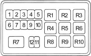
R1 Air Conditioning Compressor Clutch
R2 Starter (HC)
R3 Headlamp Washer Pump
R4 Front Wiper (On/Off)
R5 Front Wiper (Speed)
R6  –
R7 Engine Control Module (ECM)
R8 Brake Booster Pump Motor
R9 Cooling Fan High Speed (HC)
R10  –
R11  –
R12  –
R13 Cooling Fan Low Speed (HC)
R14 Cooling Fan Speed Control
R15 Headlamp (Low Beam)
R16 Rear Window Defogger
R17  –
Relay (Non-Serviceable)
R18 Front Fog Lamp
R19 Headlamp (High Beam)
R20 Horn
R21 Windshield Washer Pump
R22 Security Siren

Luggage Compartment Fuse Box

   ’10-’11:

Chevrolet Camaro - fuse box diagram - luggage compartment
Chevrolet Camaro – fuse box diagram – luggage compartment

   ’12-’15:

Chevrolet Camaro - fuse box diagram - luggage compartment
Chevrolet Camaro – fuse box diagram – luggage compartment

No.
A
Protected Component
1 7.5 Garage Door Opener, Parking Assist Control Module, Inside Rearview Mirror
2 30 Audio Amplifier
3 20 Radio
4  –
5 30 Convertible: Folding Top Control Module
6 10 Convertible: Folding Top Control Module
7  –
8  –
9 30 Electronic Suspension Control Module
10 10 Exhaust Flow Control Valve Relay Battery Voltage Supply
11  –
12  –
13 20 Engine Control Module
14 5 Body Control Module
15 20 Fuel Pump Control Module
16  –
Relay
R1  –
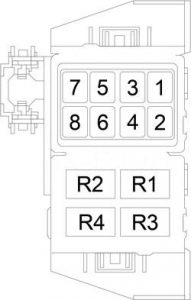
R2 Exhaust Valve Flow Control

WARNING: Terminal and harness assignments for individual connectors will vary depending on vehicle equipment level, model, and market.

Chevrolet Malibu (1997 – 2003) – fuse box diagram

Chevrolet Malibu (1997 – 2003) – fuse box diagram

Year of production: 1997, 1998, 1999, 2000, 2001, 2002, 2003

Passenger Compartment Fuse Box (Left)

Chevrolet  Malibu - fuse box diagram - passenger compartment (left)
Chevrolet Malibu – fuse box diagram – passenger compartment (left)
No.
A
Protected Component
1 25 Wipers, Multifunction Switch
2 10 Trunk Release, Remote Keyless Entry
3 10 Turn Sigals
4 10 Power Mirrors
5 10 Air Bag (Sensing & Diagnostic Module (SDM))
6 10 Body Control Module (BCM)
7 10 Powertrain Control Module (PCM)
8 15 Power Door Lock
9 10 Instrument Panel Cluster, Body Control Module
10 15 Stop Lamps
11 10 Hazard Lamps
12 10 Climate Control, Cluster, Data Link Connector
13 10 Radio
Relay
R1 Trunk Release
R2 Power Door Lock (Unlock)
R3 Power Door Lock (Lock)
R4 Driver Door Unlock
Circuit Breaker
CB1 Power Seat

Passenger Compartment Fuse Box (Right)

Chevrolet Malibu - fuse box diagram - passenger compartment (right)
Chevrolet Malibu – fuse box diagram – passenger compartment (right)
No.
A
Protected Component
1 10 Interior Lamps (Dimming)
2 2 Cruise Control Switch
3 20 Climate Control
4 10 Cruise Control Module, Brake Switch, Body Control Module (BCM)
5 10 Fog Lamps
6 10 Interior Lamps (Non-Dimming)
7 10 Radio, Clock
8 20 Sunroof
Relay
R1 Fog Lamps
Circuit Breaker
CB1 Power Windows

Engine Compartment Fuse Box

Chevrolet Malibu - fuse box diagram - engine compartment
Chevrolet Malibu – fuse box diagram – engine compartment
No.
A
Protected Component
1 30 Ignition Switch
2 30 Passenger Compartment Fuse Box (Right (Fuse: “1”, “5”, “6”))
40 Passenger Compartment Fuse Box (Left (Fuse: “2”, “4”, “8”, “CB1”)
3 30 Passenger Compartment Fuse Box (Left (Fuse: “6”, “10”, “11”, “12”)
4 50 ABS
30 Passenger Compartment Fuse Box (Right (Fuse: “1”, “5”, “6”))
5 40 Ignition Switch
6 30 Air Pump
7 40 Passenger Compartment Fuse Box (Left (Fuse: “2”, “4”, “8”, “CB1”)
40 ABS
8 30 Cooling Fan No.1 (Left)
23  –
24  –
25  –
26  –
27  –
28  –
29  –
30  –
31  –
32  –
33 30 Rear Window Defogger
34 20 Cigar Lighter, Accessory Power Outlets
35 10 Generator
10 ABS
36 15 ABS
37 10 Air Conditioning Compressor, Body Control Module (BCM)
38 10 Automatic Transaxle
39 10 Powertrain Control Module (PCM), Ignition
40 10 ABS, ABS Relay
41 10 Ignition Control Module
42 10 Back-Up Lamps, Automatic Transaxle Shift Lock Control System
43 15 Horn
44 10 Powertrain Control Module (PCM), Mass Air Flow (MAF) Sensor
45 15 Parking Lamps
46 10 Climate Control System, Air Temperature Actuator, Daytime Running Lamps Relay, Rear Window Defogger Relay
47 10 Evaporative Emission (EVAP) Canister Purge Valve, Evaporative Emission (EVAP) Canister Vent Solenoid, Powertrain Control Module (PCM), Heated Oxygen Sensors
48 15 Fuel Pump Relay, Fuel Injectors
49 10 Generator
50 15 Right Headlamp
51 15 Left Headlamp, Automatic Lamp Control Relay
52 15 Cooling Fan No.2 (Right)
53 30 Blower Motor Relay
54  –
55 15 Cooling Fan No.2 (Right)
56 Fuse Puller
57 ’97-: j  Tach Test Point for Diagnostic Testing
Relay
9 Rear Window Defogger
10  –
11 ABS
12 Cooling Fan No.1
13 Blower Motor
14 Cooling Fan No.2
15 Cooling Fan
16 Air Conditioning Compressor
17  –
18 Fuel Pump
19 Automatic Lamp Control
20 Automatic Lamp Control
21 Horn
22 Daytime Running Lamps (DRL)
Circuit Breaker
CB1 Power Windows

WARNING: Terminal and harness assignments for individual connectors will vary depending on vehicle equipment level, model, and market.

Chevrolet Malibu (2004 – 2007) – fuse box diagram

Chevrolet Malibu (2004 – 2007) – fuse box diagram

Year of production: 2004, 2005, 2006, 2007

Passenger Compartment Fuse Box

Chevrolet Malibu - fuse box diagram - passenger compartment
Chevrolet Malibu – fuse box diagram – passenger compartment
No. A Protected Component
1 15 Body Control Module (Door Locks)
2 10 Body Control Module (Interior Lamps)
3  –
4 10 Adjustable Pedals Module, Adjustable Pedals Position Switch
5 10 Vehicle Communication Interface Module (VCIM (OnStar))
6 2 Outside Rearview Mirror Switch
7 10 Heated Seat Control Module (Driver/Passenger), Heated Seat Switch (Driver/Passenger), Inside Rearview Mirror, Sunroof Control Module
8 20 Rear Window Wiper Module
9  –
10 10 Windshield Wiper/Washer Switch
11  –
12 2 Power Steering Control Module
13 30 Power Windows
14 10 Inflatable Restraint Sensing and Diagnostic Module (SDM)
15 2 A/T Shift Lock Control Assembly, Cruise Control On/Off Switch
16  –
17 10 Heating Ventilation Air Conditioning (HVAC) Control Module
18  –
19 20 Heating Ventilation Air Conditioning (HVAC) Blower Switch
20 10 Inflatable Restraint Sensing and Diagnostic Module (SDM)
21 10 Audio System
22 2 Ignition Switch
23 10 Data Link Connector (DLC), Heating Ventilation Air Conditioning (HVAC) Control Module
24 10 Instrument Panel Cluster, Theft Deterrent Control Module
Relay
R1 Blower Motor
Relay (Non-Serviceable)
R2 Power Door Lock (Lock)
R3 Power Door Lock (Unlock)
R4 Driver Door Lock Actuator (Unlock)
R5 Interior Lamps


Chevrolet Malibu - fuse box diagram - passenger compartment
Chevrolet Malibu – fuse box diagram – passenger compartment
No. Relay
R1 Accessory (Power Window, Sunroof, Heated Seat, Windshield Wiper/Washer Switch)
R2 Run (Heating Ventilation Air Conditioning (HVAC))

Luggage Compartment Fuse Box

Chevrolet Malibu - fuse box diagram - luggage compartment
Chevrolet Malibu – fuse box diagram – luggage compartment
No. A Protected Component
1  –
2 30 Driver Seat Controls
3  –
4 Resistor: Door Lock Actuator (Driver)
5 10 Evaporative Emission (EVAP) Canister Vent Solenoid Valve
6 10 Park Lamps Relay (Body Control Module (BCM), License Lamps, Park/Turn Signal Lamps, Tail Lamps, Tail/Stop and Turn Signal Lamps), Instrument Panel Dimming
7  –
8  –
9  –
10 15 Sunroof Control Module
11  –
12 20 Power Outlet (Rear)
13  –
14 15 Heated Seat Controls
15  –
16 7.5 Digital Radio Receiver, Garage Door Opener Transmitter, Remote Control Door Lock Receiver, DVD Player
17 10 Back-Up Lamps Relay
18  –
19  –
20 20 Cigar Lighter, Auxiliary Power Outlet (Console or Front)
21  –
22 10 Trunk Release Relay
23 30 Rear Window Defogger
24 10 Heated Mirrors
25 15 Fuel Pump Relay
Relay
26 Rear Window Defogger, Heated Mirrors
27 Park Lamps (Back-Up Lamps, Body Control Module (BCM), Garage Door Opener Transmitter, HVAC Control Module, License Lamps, Park/Turn Signal Lamps, Tail Lamps, Tail/Stop and Turn Signal Lamps)
28  –
29  –
30  –
31  –
32  –
33 Back-Up Lamps, Inside Rearview Mirror
34  –
35  –
36 Trunk Release
37 Fuel Pump
Diode
38 Trunk Release

Engine Compartment Fuse Box

Chevrolet Malibu - fuse box diagram - engine compartment
Chevrolet Malibu – fuse box diagram – engine compartment
No. A Protected Component
1 10 Air Conditioning Compressor Clutch Relay
2 15 3.9L (LZ9): Engine Control Module (ECM), Throttle Actuator Control (TAC) Module
15 2.2 (L61): Powertrain Control Module (PCM)
3 15 Ignition Control Module (ICM), Park/Neutral Position (PNP) Switch
4 10 1-2 Shift Solenoid Valve, 2-3 Shift Solenoid Valve, Torque Convertor Clutch Pulse Width Modulation (TCC PWM) Solenoid Valve
5 10 Fuel Injectors
6 10 Evaporative Emission (EVAP) Canister Purge Solenoid Valve, Heated Oxygen (HO2S) Sensors, Mass Air Flow (MAF)/Intake Air Temperature (IAT) Sensor
7 10 Left Headlamp (Low Beam)
8 15 Horn Relay
9 10 Right Headlamp (Low Beam)
10 15 Front Fog Lamp Relay
11 10 Left Headlamp (High Beam)
12 10 Right Headlamp (High Beam)
13 10 3.9L (LZ9): Engine Control Module (ECM)
10 2.2 (L61), 3.5L (LX9): Powertrain Control Module (PCM)
14 25 Wiper 1 Relay, Wiper 2 Relay, Windshield Wiper Motor Assembly
15 10 ABS (Electronic Brake Control Module (EBCM))
16 10 3.9L (LZ9): Engine Control Module (ECM)
10 2.2 (L61), 3.5L (LX9): Powertrain Control Module (PCM)
17 30 Cooling Fan Relay No.1
18 30 Cooling Fan Relay No.2
19 30 Blower Motor Control Module, Blower Motor Relay, “RUN” Relay
20 30 Body Control Module (BCM), Fuse (Passenger Compartment): “20”, “21”, “22”, “23”, “24”
21 30 Fuse (Passenger Compartment): “12”, “14”, “15”
22 60 Fuse (Luggage Compartment): “10”, “14”, “16”, “17”, “20”, “23”
23 60 Fuse (Luggage Compartment): “1”, “2”, “5”, “6”, “22”, “25”
24 60 ABS (Electronic Brake Control Module (EBCM))
25 50 Body Control Module, Fuse (Passenger Compartment): “1”, “2”, Accessory Relay
26 30 Starter Relay
41 80 Power Steering Control Module
42 10 Transmission Control Module
43 15 Ignition Control Module (ICM)
44 10 Fuel Injectors
45 10 Intake Manifold Tuning (IMT) Valve Solenoid
46  –
47  –
50  –
51  –
52  –
54  –
55  –
56  –
57  –
Relay
28 Cooling Fan (No.1 (Left))
29 Cooling Fan
30 Cooling Fan (No.2 (Right))
31 Starter Motor
32 Run/Crank (Ignition)
33 Engine Control Module (ECM)
34 Air Conditioning Compressor Clutch
35 Headlamp (High Beam)
36 Front Fog Lamp
37 Horn
38 Headlamp (Low Beam)
39 Wiper (No.1)
40 Wiper (No.2 – Windshield Wiper Motor)
48  –
49  –
53  –
Diode
27 Wiper 1 Relay, Wiper 2 Relay

WARNING: Terminal and harness assignments for individual connectors will vary depending on vehicle equipment level, model, and market.

Chevrolet Malibu (2008 – 2012) – fuse box diagram

Chevrolet Malibu (2008 – 2012) – fuse box diagram

Year of production: 2008, 2009, 2010, 2011, 2012

Passenger Compartment Fuse Box

The instrument panel fuse block is located on the instrument panel near the floor on the passenger side of the vehicle.

Chevrolet Malibu - fuse box diagram - passenger compartment
Chevrolet Malibu – fuse box diagram – passenger compartment
No.
A
Protected Component
1 15 Body Control Module (Door Locks)
2 10 Body Control Module (Interior Lamps)
3 2 Steering Wheel Controls
4 10 ’08: Adjustable Pedals Module, Adjustable Pedals Position Switch
5 10 Vehicle Communication Interface Module (VCIM (OnStar))
6 2 Outside Rearview Mirror Switch
7 10 Heated Seat Control Module (Driver/Passenger), Heated Seat Switch (Driver/Passenger), Inside Rearview Mirror, Sunroof Control Module
8  –
9  –
10 10 Windshield Wiper/Washer Switch
11  –
12 2 Power Steering Control Module
13 30 Power Windows
14 10 Inflatable Restraint Sensing and Diagnostic Module (SDM)
15 2 A/T Shift Lock Control Assembly, Cruise Control On/Off Switch, Passenger Airbag Status Indicator
16  –
17 10 Heating Ventilation Air Conditioning (HVAC) Control Module
18  –
19 20 Heating Ventilation Air Conditioning (HVAC) Blower Switch
20 10 Inflatable Restraint Sensing and Diagnostic Module (SDM)
21 10 Audio System
22 2 Ignition Switch
23 10 Data Link Connector (DLC), Heating Ventilation Air Conditioning (HVAC) Control Module
24 10 Instrument Panel Cluster, Theft Deterrent Control Module
Relay
R1 Blower Motor
Relay (Non-Serviceable)
R2 Power Door Lock (Lock)
R3 Power Door Lock (Unlock)
R4 Driver Door Lock Actuator (Unlock)
R5 Interior Lamps

No.
Relay
R1 Accessory (Power Window, Sunroof, Heated Seat, Windshield Wiper/Washer Switch)
R2 Run (Heating Ventilation Air Conditioning (HVAC))

Engine Compartment Fuse Box

Chevrolet Malibu - fuse box diagram - engine compartment
Chevrolet Malibu – fuse box diagram – engine compartment
No.
A
Protected Component
1 10 Air Conditioning Compressor Clutch Relay
2 15 Engine Control Module (ECM)
3 10 3.5L (LZ4, LZE): Engine Control Module (ECM)
10 2.4L (LAT): Generator Battery Disconnect Control Module, Starter Generator Control Module (SGCM)
4 10 1-2 Shift Solenoid Valve, 2-3 Shift Solenoid Valve, 4-3 Shift Solenoid Valve, Torque Convertor Clutch Pulse Width Modulation (TCC PWM) Solenoid Valve, Transmission Control Module (TCM)
5 10 3.6L (LY7): Mass Air Flow (MAF)/Intake Air Temperature (IAT) Sensor
20 2.4L (LAT): Starter Generator Control Module (SGCM) Coolant Pump, Heater Coolant Pump
6 10 Evaporative Emission (EVAP) Canister Purge Solenoid Valve, Heated Oxygen (HO2S) Sensors, Mass Air Flow (MAF)/Intake Air Temperature (IAT) Sensor (2.4L (LAT, LE5, LE9))
7 10 Left Headlamp (Low Beam)
8 15 Horn Relay
9 10 Right Headlamp (Low Beam)
10 15 Front Fog Lamp Relay
11 10 Left Headlamp (High Beam)
12 10 Right Headlamp (High Beam)
13 10 2.4L (LAT, LE5, LE9), 3.6L (LY7): Engine Control Module (ECM), Telematic Vehicle Localization and Immobilization Control Module
14 25 Wiper 1 Relay, Wiper 2 Relay, Windshield Wiper Motor Assembly
15 10 ABS (Electronic Brake Control Module (EBCM))
16 10 2.4L (LAT, LE5, LE9), 3.6L (LY7): Engine Control Module (ECM), Telematic Vehicle Localization and Immobilization Control Module
17 30 Cooling Fan Relay No.1
18 30 Cooling Fan Relay No.2
40 3.6L (LY7 – 2012): Cooling Fan Relay No.2
19 30 Blower Motor Control Module, Blower Motor Relay, “RUN” Relay
20 30 Body Control Module (BCM), Fuse (Passenger Compartment): “20”, “21”, “22”, “23”, “24”
21 30 Fuse (Passenger Compartment): “12”, “14”, “15”
22 60 Fuse (Luggage Compartment): “10”, “13”, “14”, “16”, “17”, “20”, “23”
23 60 Fuse (Luggage Compartment): “1”, “2”, “5”, “6”, “22”, “25”
24 60 ABS (Electronic Brake Control Module (EBCM))
25 50 Body Control Module, Fuse (Passenger Compartment): “1”, “2”, “5”, “6”, Accessory Relay
26 30 Starter Relay
41 80 2.4L (LE5, LE9, LAT): Power Steering Control Module
42 10 Transmission Control Module
43 15 3.6L (LY7): Fuel injectors (ODD), Ignition Coil/Modules (ODD)
15 2.4L (LE5 or LE9): Ignition Coils
15 3.5L (LZ4, LZE): Ignition Control Module
44 15 3.6L (LY7): Fuel Injectors (EVEN), Ignition Coil Modules (EVEN)
10 2.4L (LE5, LE9, LAT), 3.5L (LZ4, LZE): Fuel Injector
45 10 3.5L (LZ4, LZE), 3.6L (LY7): Heated Oxygen Sensor (HO2S) Bank 1 Sensor 2, Heated Oxygen Sensor (HO2S) Bank 2 Sensor 2
46 15 Daytime Running Light Relay
47 10 Stop Lamp Relay
50 20 Power Window
51 10 2.4L (LAT): Starter Generator Control Module (SGCM)
10 3.5L (LZ4, LZE): Engine Control Module (ECM)
52 10 Secondary Air Injection (AIR) Pump Relay
20 Transmission Auxiliary Fluid Pump Control Module
54 5 Body Control Module (Regulated Voltage Control)
15 2.4L (LAT): Body Control Module (Regulated Voltage Control)
55 30 DC/AC Inverter
56 30 ABS (Electronic Brake Control Module (EBCM))
57 20  –
Relay
28 Cooling Fan (No.1 (Left))
29 Cooling Fan
30 Cooling Fan (No.2 (Right))
31 Starter Motor
32 Run/Crank (Ignition)
33 Engine Control Module (ECM)
34 Air Conditioning Compressor Clutch
35 Headlamp (High Beam)
36 Front Fog Lamp
37 Horn
38 Headlamp (Low Beam)
39 Wiper (No.1)
40 Wiper (No.2 – Windshield Wiper Motor)
48 Daytime Running Light
49 Stop Lamp
53 Secondary Air Injection (AIR) Pump
Transmission Auxiliary Fluid Pump Control Module
Diode
27 Wiper 1 Relay, Wiper 2 Relay

Luggage Compartment Fuse Box

Chevrolet Malibu - fuse box diagram - luggage compartment
Chevrolet Malibu – fuse box diagram – luggage compartment
No.
A
Protected Component
1 30 Passenger Seat Controls
2 30 Driver Seat Controls
3  –
4  –
5 10 Evaporative Emission (EVAP) Canister Vent Solenoid Valve
6 10 Park Lamps Relay (Body Control Module (BCM), License Lamps, Park/Turn Signal Lamps, Tail Lamps, Tail/Stop and Turn Signal Lamps), Instrument Panel Dimming
7  –
8  –
9 25 Sunroof Control Module, Sunroof Shade Module
10 15 Sunroof Control Module
11  –
12  –
13 25 Audio Amplifier
14 15 Heated Seat Controls
15  –
16 7.5 Digital Radio Receiver, Garage Door Opener Transmitter, Remote Control Door Lock Receiver (RCDLR)
17 10 Back-Up Lamps Relay
18  –
19  –
20 20 Cigar Lighter, Auxiliary Power Outlet (Console or Front)
21  –
22 10 Trunk Release Relay
23 30 Rear Window Defogger
24 10 Heated Mirrors
25 15 Fuel Pump Relay
Relay
26 Rear Window Defogger, Heated Mirrors
27 Park Lamps (Back-Up Lamps, Body Control Module (BCM), Garage Door Opener Transmitter, HVAC Control Module, License Lamps, Park/Turn Signal Lamps, Tail Lamps, Tail/Stop and Turn Signal Lamps)
28  –
29  –
30  –
31  –
32  –
33 Back-Up Lamps, Inside Rearview Mirror
34  –
35  –
36 Trunk Release
37 Fuel Pump
Diode
38 Trunk Release

WARNING: Terminal and harness assignments for individual connectors will vary depending on vehicle equipment level, model, and market.

Chevrolet Malibu (2013 – 2015) – fuse box diagram

Chevrolet Malibu (2013 – 2015) – fuse box diagram

Year of production: 2013, 2014, 2015

Passenger Compartment Fuse Box

Chevrolet Malibu - fuse box diagram - passenger compartment
Chevrolet Malibu – fuse box diagram – passenger compartment
No. A Protected Component
1 2 Steering Wheel Controls Switch (Left/Right)
2 15 Body Control Module (Right Rear Turn Signal, Left Mirror Turn Signal, Left Front Turn Signal, Door Locks)
3 15 Body Control Module (Left Stoplamp, Left Daytime Running Light Lamp, Headlamp Control, Right Taillamp, Right Park/Sidemarker Lamps, Right MirrorTurn, Right Front Turn Signals)
4 15 Radio
5 7.5 Telematics Communication Interface Control Module (OnStar)
6 20 Front Accessory Power Outlet
7 20 Console Bin Power Outlet, Accessory Power Outlet 110V AC
8 15 Body Control Module (License Plate Lamp, Center High-Mounted Stoplamp, Rear Fog Lamps, Right Front Park/Sidemarker Lamps, LED Indicator Dim, Washer Pump, Right Stoplamp, Trunk Release)
9 15 Body Control Module (Left Low – Beam Headlamp, Daytime Running Light)
10 30 Body Control Module, Power Door Locks
11 40 Blower Control Module
12 25 Circuit Breaker: Passenger Seat
13 25 Circuit Breaker: Driver Seat, Seat Memory Control Module
14 7.5 Data Link Connector
15 10 Inflatable Restraint Sensing and Diagnostic Module
16 5 Rear Compartment Lid Unlatch Relay
17 10 Heater Ventilation Air Conditioning (HVAC) Control Module
18 30 Audio System
19 10 Radio Controls, Heater Ventilation Air Conditioning (HVAC) Controls, Info Display Module, Auxiliary Audio Input with Memory Card Receptacle (MCR)
20 5 Passenger Presence Module
21 5 Instrument Cluster
22 2 Ignition Switch (without BTM)
23 15 Body Control Module (Right Low – Beam Headlamp, Daytime Running Light)
24 15 Body Control Module (Ambient Light, Switch Backlighting (LED), Trunk Lamp, Shift Lock, Key Capture)
25 25 Accessory AC/DC Power Inverter Module (110V AC)
26  –
Relay
R1 Rear Compartment Lid Unlatch
R2  –
R3 Power Outlets

Engine Compartment Fuse Box

Chevrolet Malibu - fuse box diagram - engine compartment
Chevrolet Malibu – fuse box diagram – engine compartment
No. A Protected Component
1 15 Transmission Control Module (TCM)
2 10 2.5L LKW: Air Conditioning Compressor Clutch Relay
5 2.4L LUK, 2.0L LTG: Engine Control Module (ECM)
3 10 2.4L LUK, 2.0L LTG: Air Conditioning Compressor Clutch Relay
4 5 2.5L LKW: Engine Control Module (ECM)
5 5 2.4L LUK, 2.0L LTG: Engine Control Module (ECM)
6 25 Windshield Wiper Relay, Windshield Wiper Speed Control Relay
7 5 2.5L LKW: Engine Control Module (ECM)
8 15  –
9 15 Ignition Coils
10 20 Engine Control Module (ECM)
11 10 2.5L LKW, 2.0L LTG: Multifunction Intake Air Sensor, Heated Oxygen Sensor
12 40 2.5L LKW: Starter Relay No.2
30 2.4L LUK, 2.0L LTG: Starter Relay
13 7.5 2.5L LKW, 2.0L LTG: Chassis Control Module, Control Solenoid Valve Assembly, Fuel Pump Driver Control Module
7.5 2.4L LUK: Control Solenoid Valve Assembly
14 10 2.4L LUK: Auxiliary Heater Coolant Pump
15 10 2.4L LUK: Starter/Generator Coolant Pump Relay
16 7.5 2.5L LKW, 2.0L LTG: Active Grille Air Shutter Actuator
7.5 2.4L LUK: Starter/Generator Control Module, Active Grille Air Shutter Actuator
17 5 Inflatable Restraint Sensing and Diagnostic Module
18 5 2.5L LKW: Battery Isolator Control Module
19  –
20 25 2.5L LKW: Transmission Fluid Pump Relay (Auxiliary)
21 30 Rear Power Window
22 30 Sunroof Motor
23 7.5 2.4L LUK: Starter/Generator Control Module
24 30 Front Power Window
25 30 Keyless Entry Control Module
26 60 Electronic Brake Control Module (ABS – Pump)
27 30  –
28 40 Rear Window Defogger
29 15 Seat Lumbar Support Switch (Driver)
30 15 Seat Lumbar Support Switch (Passenger)
31 15 2.5L LKW, 2.0L LTG: Chassis Control Module
15 2.4L LUK: Hybrid/EV Battery Pack Cooling Fan
32 15 Body Control Module (Back-Up Lamps, Interior Lamp)
33 25 Seat Heating Control Module, Seat Memory Control Module
34 25 Electronic Brake Control Module (ABS – Valve)
35 30 Audio Amplifier
36  –
37 10 Right Headlamp (High Beam), High Beam Solenoid Actuator (Right)
38 10 Left Headlamp (High Beam), High Beam Solenoid Actuator (Left)
39  –
40  –
41  –
42 30 Cooling Fan High Speed Relay
43  –
44 20 2.5L LKW: Starter Relay No.1
30 2.4L LUK: Transmission Fluid Pump Relay (Auxiliary)
45 30 Cooling Fan Low Speed Relay
46 10 Cooling Fan Low Speed Relay, Cooling Fan Speed Control Relay
47 10 2.5L LKW: Heated Oxygen Sensor 1, Evaporative Emission Purge Solenoid Valve, Rocker Arm Actuator
10 2.0L LTG: Heated Oxygen Sensor 1, Evaporative Emission Purge Solenoid Valve, Turbocharger Bypass Solenoid Valve, Turbocharger Wastegate Solenoid Valve, Engine Oil Pressure Control Solenoid Valve
10 2.4L LUK: Heated Oxygen Sensor 1, Heated Oxygen Sensor 2, Mass Air Flow/Intake Air Temperature Sensor, Evaporative Emission Purge Solenoid Valve
48 15 Front Fog Lamps
49 15 Right Headlamp
50 15 Left Headlamp
51 15 Horn
52 5 Instrument Cluster
53 10 Inside Rearview Mirror, Rearview Camera
54 5 Heater Ventilation Air Conditioning (HVAC) Control Module, Collision Alert Indicators
55 7.5 Outside Rearview Mirror Switch, Window Switch (Driver), Garage Door Opener
56 15 Windshield Washer Pump
57 5  –
58  –
59 50 2.4L LUK: Secondary Air Injection Pump Relay
60 7.5 Outside Rearview Mirror Glass (Driver/Passenger)
61  –
62 10 Evaporative Emission Vent Solenoid Valve
63  –
64  –
65  –
66 15 2.4L LUK: Secondary Air Injection Solenoid Valve Relay
67 20 2.5L LKW, 2.0L LTG: Fuel Pump Control Module
20 2.4L LUK: Chassis Control Module
68  –
69 5 Body Control Module
70 5 Side Object Sensor Module (Left/Right), Rear Parking Assist Control Module, Vehicle Camera Module
71 5 Keyless Entry Control Module
Relay
R1 Air Conditioning Compressor Clutch
R2 Starter (No.1)
R3  –
R4 Front Wiper (Speed)
R5 Front Wiper (On/Off)
R6 2.4L LUK: Auxiliary Heater Coolant Pump
R7 Engine Control Module (ECM)
R8 2.5L LKW: Transmission Auxiliary Oil Pump
R9 Cooling Fan (No.2)
R10 Cooling Fan (No.3)
R11 2.5L LKW: Starter (No.2)
2.4L LUK: Transmission Auxiliary Oil Pump
R12  –
R13 Cooling Fan (No.1)
R14 Low Beam
R15 Run/Crank
R16 2.4L LUK: Secondary Air Injection Pump
R17 Rear Window Defogger
Relay (Non-Serviceable)
R18 Child Security Lock Disable
R19 2.4L LUK: Starter/Generator Coolant Pump
R20 Headlamp (High Beam)
R21 Horn
R22 Front Fog Lamp
R23 Windshield Washer Pump
R24 2.4L LUK, 2.5 LKW: Secondary Air Injection Pump
R25  –
R26  –

Fusible Link Block

Type 1:

Chevrolet Malibu - fuse box diagram - fusible link block type 1
Chevrolet Malibu – fuse box diagram – fusible link block type 1

Type 2:

Chevrolet Malibu - fuse box diagram - fusible link block type 2
Chevrolet Malibu – fuse box diagram – fusible link block type 2
No. A Circuit Protected
1 60 Fuse Block (Instrument Panel)
2 60 Fuse Block (Instrument Panel)
3 80 Power Steering Control Module
4 175 Type 2: Battery (Auxiliary)
5 250 Type 1: Fuse Block (Underhood)
200 Type 2: Fuse Block (Underhood)
6 300 Type 1: Generator, Starter Motor
500 Type 2: Generator, Starter Motor

WARNING: Terminal and harness assignments for individual connectors will vary depending on vehicle equipment level, model, and market.

Chevrolet Sububran (2003 – 2006) – fuse box diagram

Chevrolet Suburban (2003 – 2006) – fuse box diagram

Year of production: 2003, 2004, 2005, 2006

Passenger Compartment Fuse Box

Chevrolet Suburan - fuse box diagram - passenger compartment
Chevrolet Suburan – fuse box diagram – passenger compartment
No.
A
Protected Component
1 15 Rear Wiper/Washer Switch
2 10 HVAC Components, Electronic Suspension Control (ESC) Components, Heated Seat Modules (Rear), Wheel Steering Control Module
3 15 Front Axle Actuator, Transfer Case Shift Control Switch
4 10 Passlock Sensor, Transmission Control Module (TCM), Powertrain Control Module (PCM)
5 15 Stop Lamps, Brake Module, Electronic Throttle Actuator Control
6 15 Driver Door Module (DDM)
7 10 HVAC Control Assembly (Rear Auxiliary)
8 10 Upfitter Provisions
9 30 HVAC Control Module
10 10 HVAC Control Module, HVAC Actuators, Inside Rearview Mirror
11 10 Cruise Control Switch, Steering Wheel Speed/Position Sensor
12 10 Stop Lamp Switch, Electronic Brake Control Module (EBCM), Traction Control Switch
13 10 Body Control Module (BCM)
14 10 Center High Mounted Stop Lamp (CHMSL)
15 25 Windshield Wiper Motor Module
16 10 Body Control Module (BCM)
17 10 Left Turn Signal/Stop Trailer
18 10 Right Turn Signal/Stop Trailer
19 20 Power Outlet (D-pillar)
20 15 Body Control Module (BCM)
21 15 Body Control Module (BCM)
22 10 Left Turn Signals and Side Markers Lamps, Instrument Panel Cluster, Driver Door Module (DDM)
23 10 Right Turn Signals and Side Markers Lamps, Instrument Panel Cluster, Front Passenger Door Module (FPDM)
24 20 Door Lock/Unlock Relay
25 25 Turn Signal/Hazard Flasher Module
26 15 Body Control Module (BCM)
27 10 Front Passenger Door Module (FPDM)
Circuit Breaker
CB1 25 Left Power Window (Left Rear Power Window and Driver Door Module)
Relay
R1 Power Door Lock
R2 Power Door Unlock
R4  –
R5 Rear Fog Lamps

Engine Compartment Fuse Box

Chevrolet Suburan - fuse box diagram - engine compartment
Chevrolet Suburban – fuse box diagram – engine compartment
No.
A
Protected Component
1 40 Trailer Wiring, Automatic Level Control (ALC) Compressor Relay
2  –
3 50 Circuit Breaker (Passenger Compartment Relay Box): “CB1”, “CB2”
4 40 Blower Motor
5 50 Fuse (Passenger Compartment): “6”, “19”, “24” “27”
6 30 Off-Road Lamps, Trailer Wiring
7 60 Electronic Brake Control Module (EBCM)
8 60 Electronic Brake Control Module (EBCM), Automatic Level Control (ALC) Compressor
9 40 Ignition Switch
10  –
11 40 Ignition Switch
12 50 Fuse (Passenger Compartment): “20”, “21”, “25” “26”, “CB1”
13 15 Parking Lamps Trailer Wiring
14 10 Right Rear Parking and Side Marker Lamps
15 10 Left Rear Parking and Side Marker Lamps
16 10 Interior Lamps
17 25 Stop Lamp Switch
18 10 Body Control Module (BCM), Pass-Key Module
19 25 Sunroof Relay
20 30 Roof Beacon Relay, Off-Road Lamps
21 15 Rear Wheel Steering Control Module, Evaporative Emission (EVAP) Canister Vent Solenoid
22 30 HVAC Control Assembly (Rear Auxiliary)
23 20 Accessory Power Outlets, Auxiliary Power Outlets
24 15 Powertrain Control Module (PCM), Mass Air Flow (MFS) Sensor, Evaporative Emission (EVAP) Canister Purge Solenoid, Fuel Composition Sensor, Secondary Fuel Pump Relay
25 15 Throttle Actuator Control (TAC), Electronic Brake Controller
26 15 Odd: Ignition Coils, Fuel Injectors
27 15 Even: Ignition Coils, Fuel Injectors
28 10 A/? Compressor Relay, Park/Neutral Position (PNP) Switch, Turn Signal/Multifunction Switch, Headlamp Leveling Components, Instrument Panel Cluster, Clutch Start Switch
29 30 Automatic Level Control (ALC) Compressor, Electronic Suspension Control (ESC) Module
30 10 Backup Lamps Trailer Wiring, Back-Up Alarm, Body Control Module (BCM)
31 20 Powertrain Control Module, Fuel Pump
32 15 Oxygen Sensors
33 20 Backup Lamps, Park/Neutral Position Switch (PNP)
34 30 Rear Window Defogger Relay
35 15 Oxygen Sensors
36 15 Inflatable Restraint Sensing and Diagnostic Module (SDM), Memory Seat Module (Passenger), Inside Reaview Mirror
37 10 Front Parking Lamps, Front Side Marker Lamps
38 10 Rear Window Defogger Relay, Instrument Panel Cluster (IPC), Rear Object Sensor Control Module, Selectable Ride Switch
39 10 Body Control Module (BCM)
40 10 Left Headlamp (High Beam)
41 20 Left Headlamp (Xenon)
42 10 Daytime Running Light Relay
43 10 Instrument Panel Cluster/Driver Information Center
44 10 HVAC Control Module
45 15 Cigarette Lighter, Data Link Connector
46 10 Right Headlamp (High Beam)
47 10 Air Conditioning Compressor Relay
48 25 Rear Wiper/Washer
49  –
50 15 Audio System, Digital Radio Receiver, Rear Seat Audio
51 15 Instrument Panel Cluster (IPC), Rear Fog Lamp Relay, Overhead Console, Roof Beacon Switch, Rear Heated Seats, HomeLink (Garage Door Opener)
52 10 Left Headlamp (Low Beam)
53 10 Brake Transmission Shift Interlock System
54 10 Starting System, Powertrain Control Module (Gasoline), Engine Control Module (Diesel), Transmission Control Module (TCM)
55 10 Right Headlamp (Low Beam)
56 15 Front Fog Lamps Relay
57 15 Windshield Washer Pump
58 15 Vehicle Communication Interface Module (VCIM), Rear Seat Entertainment (RSE) Assembly, Remote Playback Device-CD Player
59 30 Radio Amplifier
60 20 Right Headlamp (Xenon)
61 15 Horn
62 15 Electronic Adjustable Pedals (EAP) Relay
63 30 Transfer Case Encoder Motor, Transfer Case Shift Control Module
64 15 Supplemental Brake Assist Pump Motor, Fuel Pump Relay (Secondary)
65 125 Cust Feed
66 10 Generator Battery Control Module
Relay
R1 Parking Lamps, Side Marker Lamps
R2 Starter
R3 Ignition
R4 Fuel Pump
R5 Headlamp High Beam
R6 Daytime Running Light
R7 Headlamp (Low Beam)
R8 Air Conditioning Compressor
R9 Front Fog Lamps
R10 Horn
R11 Windshield and Rear Window Washer Pump

Engine Compartment Relay Box (10 Series)

Chevrolet Suburan - fuse box diagram - engine compartment relay box
Chevrolet Suburban – fuse box diagram – engine compartment relay box
No.
A
Circuit Breaker
1 40 Cooling Fan Relay No.1
2 40 Cooling Fan Relay No.2
3 10 Cooling Fan Relay No.3
Relay
R1 Cooling Fan (Left)
R2 Cooling Fan (Left/Right – High Speed)
R3 Cooling Fan (Left/Right – Low Speed)

Passenger Compartment Relay Box

Chevrolet Suburban - fuse box diagram - passenger compartment relay box
Chevrolet Suburban – fuse box diagram – passenger compartment relay box
No.
A
Circuit Breaker
CB1 30 Driver and Passenger Seat Module, Memory Seat Module
CB2 25 Right Power Window (Front Passenger Door Module (FPDM), Right Rear Power Window)
Relay
R1 Rear Window Defogger
R2  –

WARNING: Terminal and harness assignments for individual connectors will vary depending on vehicle equipment level, model, and market.

Chevrolet Tahoe (2003 – 2006) – fuse box diagram

Chevrolet Tahoe (2003 – 2006) – fuse box diagram

Year of production: 2003, 2004, 2005, 2006

Passenger Compartment Fuse Box

Chevrolet Tahoe – fuse box diagram – passenger compartment
No.
A
Protected Component
1 15 Rear Wiper/Washer Switch
2 10 HVAC Components, Electronic Suspension Control (ESC) Components, Heated Seat Modules (Rear), Wheel Steering Control Module
3 15 Front Axle Actuator, Transfer Case Shift Control Switch
4 10 Passlock Sensor, Transmission Control Module (TCM), Powertrain Control Module (PCM)
5 15 Stop Lamps, Brake Module, Electronic Throttle Actuator Control
6 15 Driver Door Module (DDM)
7 10 HVAC Control Assembly (Rear Auxiliary)
8 10 Upfitter Provisions
9 30 HVAC Control Module
10 10 HVAC Control Module, HVAC Actuators, Inside Rearview Mirror
11 10 Cruise Control Switch, Steering Wheel Speed/Position Sensor
12 10 Stop Lamp Switch, Electronic Brake Control Module (EBCM), Traction Control Switch
13 10 Body Control Module (BCM)
14 10 Center High Mounted Stop Lamp (CHMSL)
15 25 Windshield Wiper Motor Module
16 10 Body Control Module (BCM)
17 10 Left Turn Signal/Stop Trailer
18 10 Right Turn Signal/Stop Trailer
19 20 Power Outlet (D-Pillar)
20 15 Body Control Module (BCM)
21 15 Body Control Module (BCM)
22 10 Left Turn Signals and Side Markers Lamps, Instrument Panel Cluster, Driver Door Module (DDM)
23 10 Right Turn Signals and Side Markers Lamps, Instrument Panel Cluster, Front Passenger Door Module (FPDM)
24 20 Door Lock/Unlock Relay
25 25 Turn Signal/Hazard Flasher Module
26 15 Body Control Module (BCM)
27 10 Front Passenger Door Module (FPDM)
Circuit Breaker
CB1 25 Left Power Window (Left Rear Power Window and Driver Door Module)
Relay
R1 Power Door Lock
R2 Power Door Unlock
R4  –
R5 Rear Fog Lamps

Engine Compartment Fuse Box

Chevrolet Tahoe - fuse box diagram - engine compartment
Chevrolet Tahoe – fuse box diagram – engine compartment
No.
A
Protected Component
1 40 Trailer Wiring, Automatic Level Control (ALC) Compressor Relay
2  –
3 50 Circuit Breaker (Passenger Compartment Relay Box): “CB1”, “CB2”
4 40 Blower Motor
5 50 Fuse (Passenger Compartment): “6”, “19”, “24” “27”
6 30 Off Road Lamps, Trailer Wiring
7 60 Electronic Brake Control Module (EBCM)
8 60 Electronic Brake Control Module (EBCM), Automatic Level Control (ALC) Compressor
9 40 Ignition Switch
10  –
11 40 Ignition Switch
12 50 Fuse (Passenger Compartment): “20”, “21”, “25” “26”, “CB1”
13 15 Parking Lamps Trailer Wiring
14 10 Right Rear Parking and Side Marker Lamps
15 10 Left Rear Parking and Side Marker Lamps
16 10 Interior Lamps
17 25 Stop Lamp Switch
18 10 Body Control Module (BCM), Pass-Key Module
19 25 Sunroof Relay
20 30 Roof Beacon Relay, Off-Road Lamps
21 15 Rear Wheel Steering Control Module, Evaporative Emission (EVAP) Canister Vent Solenoid
22 30 HVAC Control Assembly (Rear Auxiliary)
23 20 Accessory Power Outlets, Auxiliary Power Outlets
24 15 Powertrain Control Module (PCM), Mass Air Flow (MFS) Sensor, Evaporative Emission (EVAP) Canister Purge Solenoid, Fuel Composition Sensor, Secondary Fuel Pump Relay
25 15 Throttle Actuator Control (TAC), Electronic Brake Controller
26 15 Odd: Ignition Coils, Fuel Injectors
27 15 Even: Ignition Coils, Fuel Injectors
28 10 A/? Compressor Relay, Park/Neutral Position (PNP) Swtich, Turn Signal/Multifunction Switch, Headlamp Leveling Components, Instrument Panel Cluster, Clutch Start Switch
29 30 Automatic Level Control (ALC) Compressor, Electronic Suspension Control (ESC) Module
30 10 Backup Lamps Trailer Wiring, Back-Up Alarm, Body Control Module (BCM)
31 20 Powertrain Control Module, Fuel Pump
32 15 Oxygen Sensors
33 20 Backup Lamps, Park/Neutral Position Switch (PNP)
34 30 Rear Window Defogger Relay
35 15 Oxygen Sensors
36 15 Inflatable Restraint Sensing and Diagnostic Module (SDM), Memory Seat Module (Passenger), Inside Reaview Mirror
37 10 Front Parking Lamps, Front Side Marker Lamps
38 10 Rear Window Defogger Relay, Instrument Panel Cluster (IPC), Rear Object Sensor Control Module, Selectable Ride Switch
39 10 Body Control Module (BCM)
40 10 Left Headlamp (High Beam)
41 20 Left Headlamp (Xenon)
42 10 Daytime Running Light Relay
43 10 Instrument Panel Cluster/Driver Information Center
44 10 HVAC Control Module
45 15 Cigarette Lighter, Data Link Connector
46 10 Right Headlamp (High Beam)
47 10 Air Conditioning Compressor Relay
48 25 Rear Wiper/Washer
49  –
50 15 Audio System, Digital Radio Receiver, Rear Seat Audio
51 15 Insturment Panel Cluster (IPC), Rear Fog Lamp Relay, Overhead Console, Roof Beacon Switch, Rear Heated Seats, HomeLink (Garage Door Opener)
52 10 Left Headlamp (Low Beam)
53 10 Brake Transmission Shift Interlock System
54 10 Starting System, Powertrain Control Module (Gasoline), Engine Control Module (Diesel), Transmission Control Module (TCM)
55 10 Right Headlamp (Low Beam)
56 15 Front Fog Lamps Relay
57 15 Windshield Washer Pump
58 15 Vehicle Communication Interface Module (VCIM), Rear Seat Entertainment (RSE) Assembly, Remote Playback Device-CD Player
59 30 Radio Amplifier
60 20 Right Headlamp (Xenon)
61 15 Horn
62 15 Electronic Adjustable Pedals (EAP) Relay
63 30 Transfer Case Encoder Motor, Transfer Case Shift Control Module
64 15 Supplemental Brake Assist Pump Motor, Fuel Pump Relay (Secondary)
65 125 Cust Feed
66 10 Generator Battery Control Module
Relay
R1 Parking Lamps, Side Marker Lamps
R2 Starter
R3 Ignition
R4 Fuel Pump
R5 Headlamp High Beam
R6 Daytime Running Light
R7 Headlamp (Low Beam)
R8 Air Conditioning Compressor
R9 Front Fog Lamps
R10 Horn
R11 Windshield and Rear Window Washer Pump

Engine Compartment Relay Box (10 Series)

Chevrolet Tahoe - fuse box diagram - engine compartment relay box
Chevrolet Tahoe – fuse box diagram – engine compartment relay box
No.
A
Circuit Breaker
1 40 Cooling Fan Relay No.1
2 40 Cooling Fan Relay No.2
3 10 Cooling Fan Relay No.3
Relay
R1 Cooling Fan (Left)
R2 Cooling Fan (Left/Right – High Speed)
R3 Cooling Fan (Left/Right – Low Speed)

Passenger Compartment Relay Box

Chevrolet Tahoe - fuse box diagram - passenger compartment relay box
Chevrolet Tahoe – fuse box diagram – passenger compartment relay box
No.
A
Circuit Breaker
CB1 30 Driver and Passenger Seat Module, Memory Seat Module
CB2 25 Right Power Window (Front Passenger Door Module (FPDM), Right Rear Power Window)
Relay
R1 Rear Window Defogger
R2  –

WARNING: Terminal and harness assignments for individual connectors will vary depending on vehicle equipment level, model, and market.

Chevrolet Avalanche (2003 – 2006) – fuse box diagram

Chevrolet Avalanche (2003 – 2006) – fuse box diagram

Year of production: 2003, 2004, 2005, 2006

Engine Compartment Fuse Box

Chevrolet Avalanche - fuse box diagram - engine compartment
Chevrolet Avalanche – fuse box diagram – engine compartment
No.
A
Protected Component
1 40 Trailer Wiring, Automatic Level Control (ALC) Compressor Relay
2  –
3 50 Circuit Breaker (Passenger Compartment Relay Box): “CB1”, “CB2”
4 40 Blower Motor
5 50 Fuse (Passenger Compartment): “6”, “19”, “24” “27”
6 30 Off Road Lamps, Trailer Wiring
7 60 Electronic Brake Control Module (EBCM)
8 60 Electronic Brake Control Module (EBCM), Automatic Level Control (ALC) Compressor
9 40 Ignition Switch
10  –
11 40 Ignition Switch
12 50 Fuse (Passenger Compartment): “20”, “21”, “25” “26”, “CB1”
13 15 Parking Lamps Trailer Wiring
14 10 Right Rear Parking and Side Marker Lamps
15 10 Left Rear Parking and Side Marker Lamps
16 10 Interior Lamps
17 25 Stop Lamp Switch
18 10 Body Control Module (BCM), Pass-Key Module
19 25 Sunroof Relay
20 30 Roof Beacon Relay, Off-Road Lamps
21 15 Rear Wheel Steering Control Module, Evaporative Emission (EVAP) Canister Vent Solenoid
22 30 HVAC Control Assembly (Rear Auxiliary)
23 20 Accessory Power Outlets, Auxiliary Power Outlets
24 15 Powertrain Control Module (PCM), Mass Air Flow (MFS) Sensor, Evaporative Emission (EVAP) Canister Purge Solenoid, Fuel Composition Sensor, Secondary Fuel Pump Relay
25 15 Throttle Actuator Control (TAC), Electronic Brake Controller
26 15 Odd: Ignition Coils, Fuel Injectors
27 15 Even: Ignition Coils, Fuel Injectors
28 10 A/? Compressor Relay, Park/Neutral Position (PNP) Swtich, Turn Signal/Multifunction Switch, Headlamp Leveling Components, Instrument Panel Cluster, Clutch Start Switch
29 30 Automatic Level Control (ALC) Compressor, Electronic Suspension Control (ESC) Module
30 10 Backup Lamps Trailer Wiring, Back-Up Alarm, Body Control Module (BCM)
31 20 Powertrain Control Module, Fuel Pump
32 15 Oxygen Sensors
33 20 Backup Lamps, Park/Neutral Position Switch (PNP)
34 30 Rear Window Defogger Relay
35 15 Oxygen Sensors
36 15 Inflatable Restraint Sensing and Diagnostic Module (SDM), Memory Seat Module (Passenger), Inside Reaview Mirror
37 10 Front Parking Lamps, Front Side Marker Lamps
38 10 Rear Window Defogger Relay, Instrument Panel Cluster (IPC), Rear Object Sensor Control Module, Selectable Ride Switch
39 10 Body Control Module (BCM)
40 10 Left Headlamp (High Beam)
41 20 Left Headlamp (Xenon)
42 10 Daytime Running Light Relay
43 10 Instrument Panel Cluster/Driver Information Center
44 10 HVAC Control Module
45 15 Cigarette Lighter, Data Link Connector
46 10 Right Headlamp (High Beam)
47 10 Air Conditioning Compressor Relay
48  –
49  –
50 15 Audio System, Digital Radio Receiver, Rear Seat Audio
51 15 Insturment Panel Cluster (IPC), Rear Fog Lamp Relay, Overhead Console, Roof Beacon Switch, Rear Heated Seats, HomeLink (Garage Door Opener)
52 10 Left Headlamp (Low Beam)
53 10 Brake Transmission Shift Interlock System
54 10 Starting System, Powertrain Control Module (Gasoline), Engine Control Module (Diesel), Transmission Control Module (TCM)
55 10 Right Headlamp (Low Beam)
56 15 Front Fog Lamps Relay
57 15 Windshield Washer Pump
58 15 Vehicle Communication Interface Module (VCIM), Rear Seat Entertainment (RSE) Assembly, Remote Playback Device-CD Player
59 30 Radio Amplifier
60 20 Right Headlamp (Xenon)
61 15 Horn
62 15 Electronic Adjustable Pedals (EAP) Relay
63 30 Transfer Case Encoder Motor, Transfer Case Shift Control Module
64 15 Supplemental Brake Assist Pump Motor, Fuel Pump Relay (Secondary)
65 125 Cust Feed
66 10 Generator Battery Control Module
Relay
R1 Parking Lamps, Side Marker Lamps
R2 Starter
R3 Ignition
R4 Fuel Pump
R5 Headlamp High Beam
R6 Daytime Running Light
R7 Headlamp (Low Beam)
R8 Air Conditioning Compressor
R9 Front Fog Lamps
R10 Horn
R11 Windshield and Rear Window Washer Pump

Passenger Compartment Fuse Box

Chevrolet Avalanche - fuse box diagram - passenger compartment
Chevrolet Avalanche – fuse box diagram – passenger compartment
No.
A
Protected Component
1  –
2 10 HVAC Components, Electronic Suspension Control (ESC) Components, Heated Seat Modules (Rear), Wheel Steering Control Module
3 15 Front Axle Actuator, Transfer Case Shift Control Switch
4 10 Passlock Sensor, Transmission Control Module (TCM), Powertrain Control Module (PCM)
5 15 Stop Lamps, Brake Module, Electronic Throttle Actuator Control
6 15 Driver Door Module (DDM)
7 10 HVAC Control Assembly (Rear Auxiliary)
8 10 Upfitter Provisions
9 30 HVAC Control Module
10 10 HVAC Control Module, HVAC Actuators, Inside Rearview Mirror
11 10 Cruise Control Switch, Steering Wheel Speed/Position Sensor
12 10 Stop Lamp Switch, Electronic Brake Control Module (EBCM), Traction Control Switch
13 10 Body Control Module (BCM)
14 10 Center High Mounted Stop Lamp (CHMSL)
15 25 Windshield Wiper Motor Module
16 10 Body Control Module (BCM)
17 10 Left Turn Signal/Stop Trailer
18 10 Right Turn Signal/Stop Trailer
19 20 Power Outlet (D-Pillar)
20 15 Body Control Module (BCM)
21 15 Body Control Module (BCM)
22 10 Left Turn Signals and Side Markers Lamps, Instrument Panel Cluster, Driver Door Module (DDM)
23 10 Right Turn Signals and Side Markers Lamps, Instrument Panel Cluster, Front Passenger Door Module (FPDM)
24 20 Door Lock/Unlock Relay
25 25 Turn Signal/Hazard Flasher Module
26 15 Body Control Module (BCM)
27 10 Front Passenger Door Module (FPDM)
Circuit Breaker
CB1 25 Left Power Window (Left Rear Power Window and Driver Door Module)
Relay
R1 Power Door Lock
R2 Power Door Unlock
R4  –
R5 Rear Fog Lamps

Passenger Compartment Relay Box

Chevrolet Avalanche - fuse box diagram - passenger compartment relay
Chevrolet Avalanche – fuse box diagram – passenger compartment relay
No.
A
Circuit Breaker
CB1 30 Driver and Passenger Seat Module, Memory Seat Module
CB2 25 Right Power Window (Front Passenger Door Module (FPDM), Right Rear Power Window)
Relay
R1 Rear Window Defogger
R2  –

Engine Compartment Relay Box (10 Series)

Chevrolet Avalanche - fuse box diagram - engine compartment relay
Chevrolet Avalanche – fuse box diagram – engine compartment relay
No.
A
Circuit Breaker
1 40 Cooling Fan Relay No.1
2 40 Cooling Fan Relay No.2
3 10 Cooling Fan Relay No.3
Relay
R1 Cooling Fan (Left)
R2 Cooling Fan (Left/Right – High Speed)
R3 Cooling Fan (Left/Right – Low Speed)

WARNING: Terminal and harness assignments for individual connectors will vary depending on vehicle equipment level, model, and market.

Chevrolet Silverado (2007 – 2013) – fuse box diagram

Chevrolet Silverado (2007 – 2013) – fuse box diagram

Year of production: 2007, 2008, 2009, 2010, 2011, 2012, 2013

Passenger Compartment Fuse Box

Chevrolet Silverado - fuse box diagram - passenger compartment
Chevrolet Silverado – fuse box diagram – passenger compartment
No.
A
Protected Component
1 20 Rear Seats
2 20 Accessory Power Outlet (Center Console), Accessory Power Outlet – (Center Console Compartment), Accessory Power Outlet (Center Seat)
3 2 Steering Wheel Control Switch Assembly – Left/Right
4 15 Door Lock/Window Switch (Driver)
5 15 Dome Lamps, Driver Side Turn Signal, Body Control Module (BCM)
6 15 Body Control Module (BCM), Trailer Stop/Turn Relay (Left)
7 10 Instrument Panel Back Lighting, Body Control Module (BCM)
8 15 Body Control Module (BCM), Trailer Stop/Turn Relay (Right)
9 15 Garage Door Opener, Door Lock/Window Switch (Passenger), Roof Beacon Switch
10 15 Power Door Lock 2 (Unlock Feature)
11 15 Power Door Lock 2 (Lock Feature)
12 15 Stop Lamps, Center-High Mounted Stop Lamp, Body Control Module (BCM), Body Control Module (BCM)
13 30 Rear Climate Controls
14 2 Outside Rearview Mirror Switch
15 10 Body Control Module (BCM)
16 20 Accessory Power Outlet (Center Console), Accessory Power Outlet – (Center Console Compartment), Accessory Power Outlet – (I/P 2)
17 10 Interior Lamps, Body Control Module (BCM)
18 15 Unlock: Door Latch – Left Rear/Right Rear (Crew Cab)
19 5 Video Display, Rear Seat Entertainment
20 10 Rear Object Sensor Control Module (Ultrasonic Rear Parking Assist)
21 15 Lock: Door Latch – Left Rear/Right Rear (Crew Cab)
22 10 Vehicle Communication Interface Module (VCIM) / Driver Information Center (DIC)
23 25  –
24 30 Seat Climate Control Module
25 10 Memory Seat Module, Remote Control Door Lock Receiver
26 15 Driver Power Door Lock (Unlock Feature)
Circuit Breaker
CB1 25 Door Lock Window Switch (Driver), Window Switch (Driver), Window Switch (Left Rear)
Relay (Non-Serviceable)
R1 Lock PCB (Door Latch – Driver/Passenger, Door Latch – Left Rear/Right Rear (Crew Cab))
R2 Lock/Unlock PCB (Door Latch – Left Rear/Right Rear (Crew Cab))
R3 Unlock PCB  (Door Latch – Driver/Passenger, Door Latch – Left Rear/Right Rear (Crew Cab))

Passenger Compartment Relay Box

Chevrolet Silverado - fuse box diagram - passenger compartment relay
Chevrolet Silverado – fuse box diagram – passenger compartment relay
No.
A
Circuit Breaker
CB1 25 Passenger Side Power Window
CB2 25 Passenger Seat
CB3 25 Driver Seat
CB4 25 Rear Sliding Window

Engine Compartment Fuse Box

Chevrolet Silverado - fuse box diagram - engine compartment
Chevrolet Silverado – fuse box diagram – engine compartment
No.
A
Protected Component
1 10 Gasoline: Right Trailer Stop/Turn Lamp (Trailer Wiring), Auxiliary Body Control Module (XBCM)
2  –
3 30  –
4 10 Left Trailer Stop/Turn Lamp (Trailer Wiring), Auxiliary Body Control Module (XBCM)
5 15 Diesel: Mass Air Flow (MAF)/Intake Air Temperature (IAT) Sensor
15 Gasoline: Central Sequential Fuel Injection (Central SFI) (4.3L), Evaporative Emissions (EVAP) Canister Purge Solenoid Valve (4.8L/5.3L/6.0L/6.2L), Mass Air Flow (MAF)/Intake Air Temperature (IAT) Sensor (4.8L/5.3L/6.0L/6.2L), Valve Lifter Oil Manifold (VLOM) Assembly (5.3L/6.0L/6.2L), Cooling Fan (Low Speed) Relay (HP2)
6 15 Gasoline: Engine Control Module (ECM), Evaporative Emission (EVAP) Canister Purse Solenoid Valve (4.3L), Mass Air Flow (MAF)/Intake Air Temperature (IAT) Sensor (4.3L)
7 10 Diesel: Right Trailer Stop/Turn Lamp (Trailer Wiring), Auxiliary Body Control Module (XBCM)
15 Gasoline: Integrated Trailer Brake Control Module
8 15 Windshield Washer Fluid Pump
9 15 Diesel (’07-’11): Glow Plug Control Module (GPCM), Fuel Heater
10 Gasoline: Heated Oxygen Sensors
10 25 Electronic Brake Control Module (EBCM)
11 10 Trailer Wiring, Backup Alarm
12 20 Headlamp (Left Low Beam)
13 10 Engine Control Module (ECM)
14 20 Gasoline: Fuel Injector (2, 4, 6, 8), Ignition Coil (2, 4, 6, 8)
25 Diesel (’07-’10): Engine Control Module (ECM)
30 Diesel (’11-’13): Engine Control Module (ECM)
15 15 Gasoline: Transmission Control Module (TCM), Evaporative Emission (EVAP) Canister Vent Solenoid Valve, Automatic Transmission
15 Diesel: Transmission Control Module (TCM), Front Drive Axle Actuator, Glow Plug Control Module (’12-’13)
16 10 Backup Lamps
17 20 Headlamp (Right Low Beam)
18 10 A/C Compressor Clutch
19 10 Gasoline: Heated Oxygen Sensors
15 Diesel: Engine Control Module (ECM), Reductant Sensor Module
20 15 Gasoline: Transmission Control Module (TCM), 1-2 Shift Solenoid (SS) Valve, 2-3 Shift Solenoid (SS) Valve, 3-2 Shift Solenoid (SS) Valve, Torque Converter Clutch (TCC) Solenoid Valve, Torque Converter Clutch Pulse Width Modulation (TCC PWM) Solenoid Valve, Input Speed Sensor (ISS), Front Drive Axle Actuator, Automatic Transmission, Drive Motor Generator Power inverter module
21 20 ’07-’10: Fuel Pump and Sender Assembly – Front, Fuel Pump
25 ’11-’13: Fuel Pump and Sender Assembly – Front, Fuel Pump
22 20 Gasoline: Fuel System Control Module (FSCM) (except 4.3L)
15 Diesel: Integrated Trailer Brake Control Module
23  –
24  –
25 20 Gasoline (except 4.3L): Fuel Injector (1, 3, 5, 7), Ignition Coil (1, 3, 5, 7)
20 Gasoline (4.3L): Ignition Control Module (ICM)
26 15 Trailer Wiring
27 15 License Lamp (Left), Marker Lamp (Left), Park/Turn Signal Lamp (Left), Tail/Stop and Turn Signal Lamp (Left), Clearance Lamps (Left), Roof Marker Lamps
28 15 Marker Lamp (Right), Park/Turn Signal Lamp (Right), Tail/Stop and Turn Signal Lamp (Right), License Lamp (Right), Clearance Lamps (Right), Marker Lamp (Tailgate)
29 15 Front Fog Lamps
30 15 Horn
31 10 Headlamp (Right High Beam)
32 15 Fuse: “34”
33 10 Headlamp (Left High Beam)
34 15 Fuse: “12”, “17”
35 30 Sunroof Module, Roof Beacon Relay
36 2 Ignition Switch, Theft Deterrent Module (TDM)
37 25 WIPER CONTROL PCB Relay
38 30 Emergency Vehicle Roof Lamp Relay
39 15 PARK ENABLE PCB Relay, ELECTRONIC ADJUSTABLE PEDALS PCB Relay
40 10 HVAC Control Module
41 10 Inflatable Restraint Sensing and Diagnostic Module (SDM), Inflatable Restraint Passenger Air Bag On/Off Indicator, Inflatable Restraint I/P Module Disable Switch
42 30 Audio Amplifier
43 15 Digital Radio Receiver, Radio, Rear Seat Audio (RSA) Control, Chime Module
44 10 Auxiliary Body Control Module (XBCM), Stop Lamp Switch, Transfer Case Shift Control Module, Trailer Brake Control Module, Serial Data Gateway (SDG) Module
45 15  –
46 15 Inflatable Restraint Passenger Presence System (PPS) Module, Inflatable Restraint Sensing and Diagnostic Module (SDM), Inflatable Restraint Vehicle Rollover Sensor (ASF)
47  –
48 10 Body Control Module (BCM), Instrument Panel Cluster (IPC)
49 15 Auxiliary Body Control Module (XBCM), Power Take Off Relay (PTO), Run Relay (TP2), Security Indicator Lamp, Vehicle Inclination Sensor, Vehicle Shock Sensor
50 10 Instrument Panel Cluster (IPC), Inside Rearview Mirror (ISRVM), Heated Steering wheel Module Control
51 15 Center High Mounted Stop Lamp (CHMSL)
52 30 Rear Window Defogger
53 15 Outside Rearview Mirrors (Heater)
54 15 Auxiliary Body Control Module (XBCM), Security Indicator Lamp, Vehicle Inclination Sensor, Vehicle Shock Sensor
55 20 Accessory Power Outlet (I/P 1), Data Link Connector (DLC)
56 10  –
57 10 Air Temperature Actuators, Mode Actuator, Recirculation Actuator
58 15 Engine Control Module (ECM), Fuel Pump Relay (Secondary), Fuel Pump Flow Control Module (except 4.3L), Electronic Brake Control Module (EBCM), Fuel System Control Module (Diesel)
59 40 Gasoline: Cooling Fan (Low Speed) Relay
60 40  –
61 60 Electronic Brake Control Module (EBCM)
62 40 Gasoline: Cooling Fan (High Speed) Relay
63 40 Electronic Brake Control Module (EBCM)
64 40 Starter
65 30 Blunt Cut Wire, Integrated Trailer Brake Control
66 60 Fuse Block
67 30  –
68 60 Windshield Washer Solvent Heater
69 30 Transfer Case Shift Control Module, Transfer Case Encoder Motor
70 40 Trailer Wiring
71 60 DRIVER SEAT 2 Circuit Breaker, PASS SEAT 1 Circuit Breaker, PWR REAR WNDW Circuit Breaker, RT DOORS Circuit Breaker
72 40 Blower Motor Control Module
73 30  –
74 60 Fuse Block
80 10 Diesel: Cooling Fan Relay
81 15 Diesel: Transmission Control Module (TCM)
Relay
R1 Gasoline: Cooling Fan (High Speed)
R2 Gasoline: Cooling Fan (Low Speed)
R3  –
R4 Gasoline: Cooling Fan Control
Diesel: Cooling Fan
R5 Headlamp (Low Beam)
R6 Front Fog Lamps
R7 Air Conditioning Compressor
R8 Starter
R9 Powertrain Control Module
R10 Fuel Pump
R11 Parking Lamps
R12 Rear Window Defogger
R13 Ignition
Non-Serviceable
R14 Back-Up Lamps
R15 Center High Mounted Stop Lamp
R16 Daytime Running Lamps
R17 Washer Fluid Pump (Front)
R18 Headlamp (High Beam)
R19 Horn
R20 Liftgate Release
R21 Power Door Lock
R22 Power Door Unlock
R23 Washer Fluid Pump (Rear)
R24 Left Trailer Stop Lamp
R25 Right Trailer Stop Lamp
R26 Wiper Motor (Control)
R27 Windshield Wiper Motor (Speed)

Engine Compartment Fuse Box No.2 (HP2)

Chevrolet Silverado - fuse box diagram - engine compartment fuse box no. 2
Chevrolet Silverado – fuse box diagram – engine compartment fuse box no. 2
No.
A
Protected Component
1 25  –
2 15 Generator Battery Vent Fan Relay
3 15 A/C Compressor
4 10 Heater Coolant Pump
5  –
6 15 Generator Control Module Coolant Pump – Left/Right
7 15 Electronic Power Steering Motor Control Module
8 15 Drive Motor Generator Power Inverter Module
9 15 Drive Motor Generator Power Inverter Module
10 15 Drive Motor Generator Battery Control Module, Serial Data Gateway (SDG) Module
11 40 FAN LO Relay, FAN MID 1 Relay
12 60 Auxiliary Transmission Pump Control Module
13 40 FAN HI Relay, FAN MID 2 Relay
14 200 Main
Relay
R1 Cooling Fan – Left
R2 Engine Cooling Fan Resistor – Left
R3 Heater Coolant Pump
R4 Cooling Fan – Right
R5 Cooling Fan – Right
R6 Generator Control Module Coolant Pump – Left/Right
R7 Cooling Fan – Left

WARNING: Terminal and harness assignments for individual connectors will vary depending on vehicle equipment level, model, and market.