Mercury Mariner (2005 – 2007) – fuse box diagram
Year of production: 2005, 2006, 2007
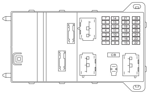
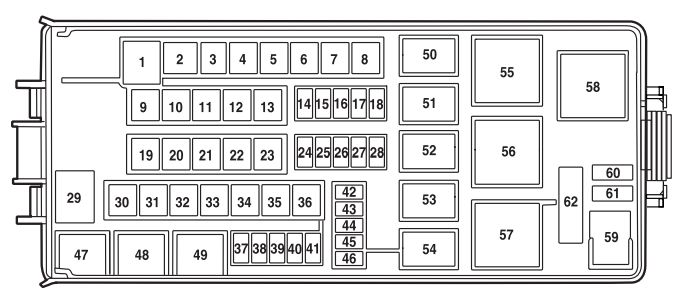
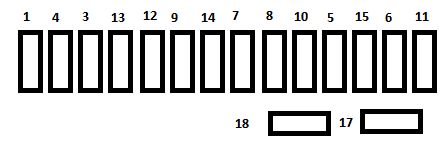
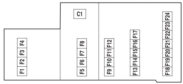
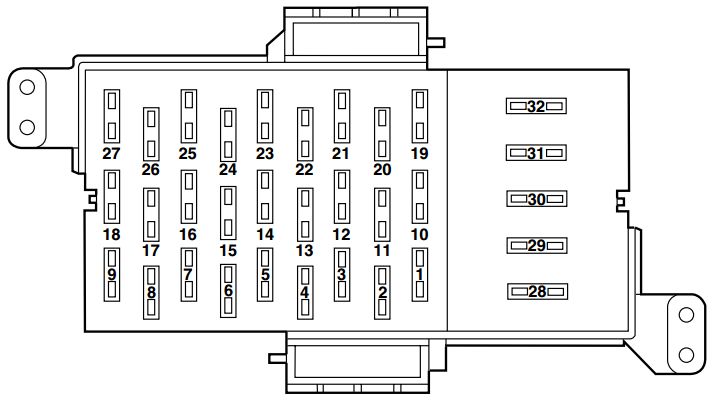
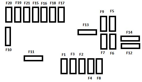
Passenger compartment fuse panel
The fuse panel is located on the right-hand side of the center console, by the instrument panel.
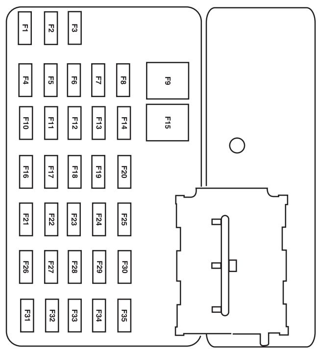
| Fuse/relay | Ampere rating [A] | Description |
| 1 | 15 | Trailer tow park lamps |
| 2 | — | Not used |
| 3 | 15* | Front and rear park lamps |
| 4 | 10* | Ignition switch |
| 5 | 2* | Powertrain Control Module (PCM relay), Fuel pump relay, Main fan relay, High/Low speed fan relay 2, PATS module |
| 6 | 15* | Center High-Mounted Stop Lamp (CHMSL), Stop lamps, PCM, Anti-lock Brake System (ABS), Speed control, Brake On-Off switch |
| 7 | 10* | Instrument cluster, Diagnostic connector, Power mirror switch, Radio |
| 8 | 5* | Canister vent (’07) |
| 9 | 30** | Power door locks, Power seats |
| 10 | 15* | Heated mirrors |
| 11 | 15* | Sunroof, Electrochromatic mirror, Compass |
| 12 | 5* | Radio |
| 13 | — | Not used |
| 14 | — | Not used |
| 15 | 30** | Power windows |
| 16 | 15* | Subwoofer |
| 17 | 15* | Low beams |
| 18 | 10* | 4WD |
| 19 | — | Not used |
| 20 | 15* | Horn |
| 21 | 10* | ’05-’06: Rear wiper motor, Rear wiper washer |
| 15 | ’07: Rear wiper motor, Rear wiper washer | |
| 22 | 10* | Instrument cluster |
| 23 | — | Not used |
| 24 | 20* | Cigar lighter |
| 25 | 20* | Front wiper motor, Front wiper washer |
| 26 | 5* | Climate control system mode switch |
| 27 | 5* | Canister vent (’05-’06), Speed control cancel switch |
| 28 | 10* | Instrument cluster |
| 29 | 10* | Reverse park aid |
| 30 | — | Not used |
| 31 | — | Not used |
| 32 | 10* | Brake-Transmission shift lock |
| 33 | 15* | Air bag module, Passenger Air bag Deactivation (PAD) indicator lamp, Occupant Classification Sensor (OCS) |
| 34 | 5* | ABS module, Evac and Fill, Speed control |
| 35 | 5* | Heated seats module, 4WD |
| * Mini fuse ** Cartridge fuse | ||
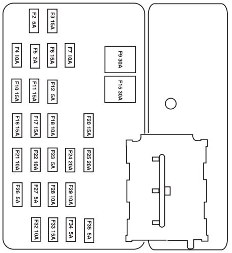
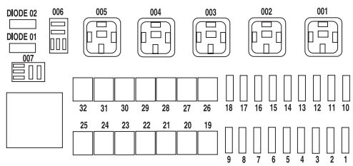
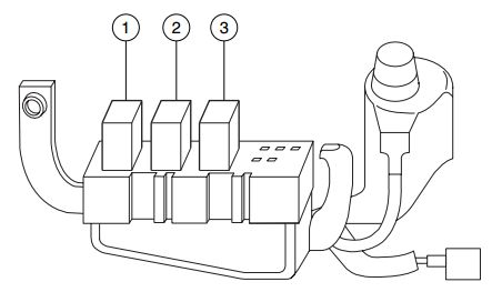
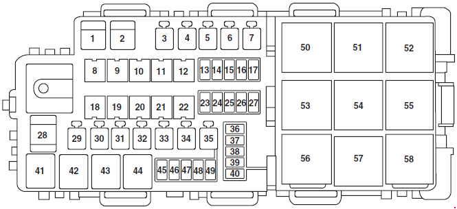
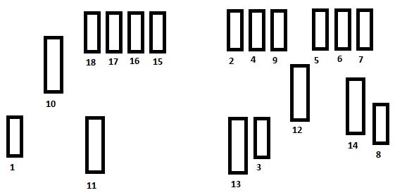
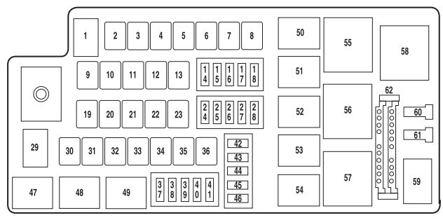
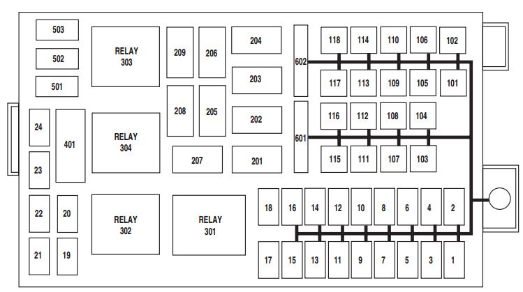
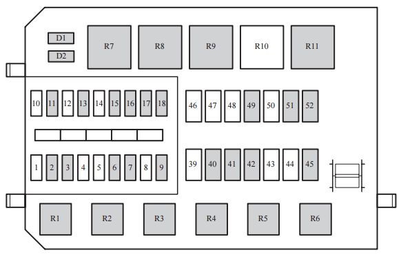
Power distribution box
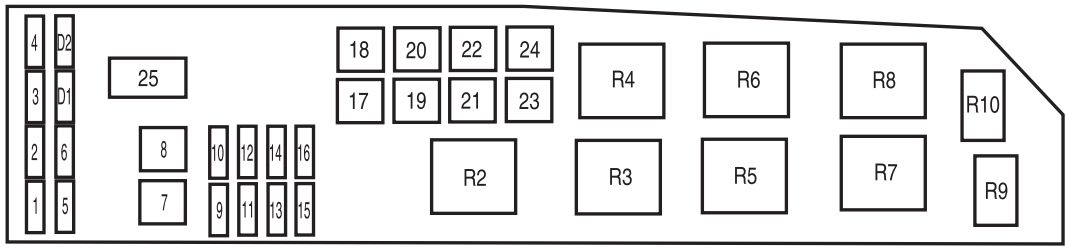
The power distribution box is located in the engine compartment. The power distribution box contains high-current fuses that protect your vehicle’s main electrical systems from overloads.
| Fuse/relay | Ampere rating [A] | Description |
| 1 | — | Not used |
| 2 | 25* | Headlamp power |
| 3 | 25* | High beams, Turn signals, Interior lamps, Headlamp power |
| 4 | 5* | Keep Alive Power (KA PWR) |
| 5 | 15* | Heated Exhaust Gas Oxygen (HEGO) sensors |
| 6 | 20* | Fuel pump |
| 7 | 40** | RUN/ACC relay – Electrochromatic mirror, Cigar lighter, Front and rear wipers, Compass |
| 8 | 30** | Powertrain Control Module (PCM), Injectors and coil |
| 9 | 15* | Alternator |
| 10 | 30* | Heated seats |
| 11 | 10* | PCM |
| 12 | 20* | Power point |
| 13 | 20* | Fog lamps |
| 14 | 15* | A/C clutch, A/C relay |
| 15 | 30* | Anti-lock Brake System (ABS) solenoid |
| 16 | 25* | I/P fuse panel (RUN/START) |
| 17 | 50** | Ignition (main) |
| 18 | 40* | Blower motor |
| 19 | 40** | Accessory delay relay – Subwoofer and 4WD, Low beam |
| 20 | 60** | ABS |
| 21 | 40** | Horn, CHMSL, Cluster, Power locks and power seats |
| 22 | 40**(I4) | 2.3 L: Cooling fan |
| 50** (V6) | 3.0 L:Cooling fan | |
| 23 | 40** | Rear defroster, Park lamps relay |
| 24 | 40** (I4) | 2.3 L: High/Low speed fan |
| 50** (V6) | 3.0 L:High/Low speed fan | |
| 25 | — | Shunt |
| Relay | ||
| R2 | PCM | |
| R3 | Fuel pump relay | |
| R4 | Cooling fan relay | |
| R5 | High/Low speed fan relay 1 | |
| R6 | Blower motor relay | |
| R7 | Starter relay | |
| R8 | High/Low speed fan relay 2 | |
| R9 | Fog lamps relay | |
| R10 | A/C relay | |
| Diode | ||
| D1 | — | |
| D2 | A/C diode | |
| * Mini fuse **Cartridge fuse | ||
WARNING: Terminal and harness assignments for individual connectors will vary depending on vehicle equipment level, model, and market