Citroen C3 mk1 (2002 – 2009) – fuse box diagram
Year of production: 2002, 2003, 2004, 2005, 2006, 2007, 2008, 2009
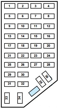
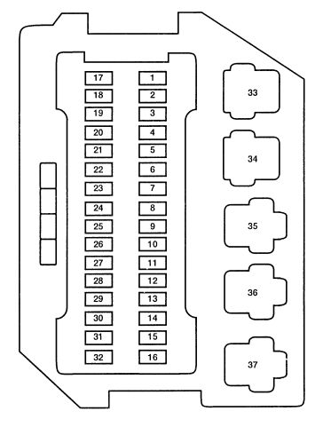
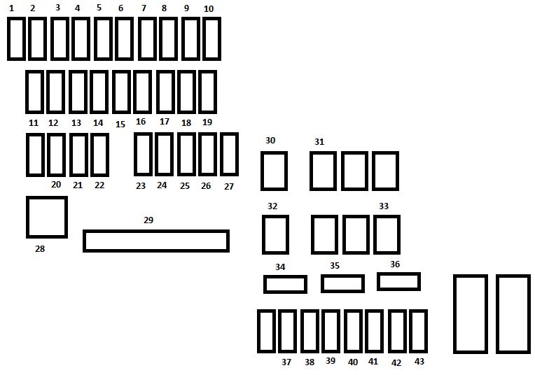
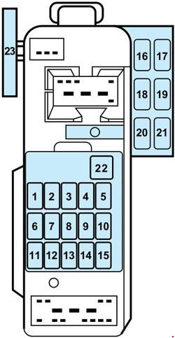
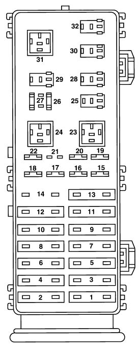
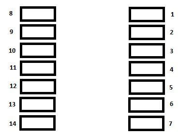
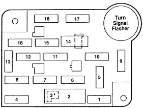
Fuse box under dashboard

| Fuse | Ampere rating [A] | Function |
| 3 | 5 | Airbags |
| 4 | 10 | Diagnostic socket, particle filter additive, clutch switch, steering angle sensor |
| 5 | 30 | Rear window, sun roof |
| 6 | 30 | Screen wash |
| 8 | 20 | Digital clock, controls at the steering wheel, radio, display |
| 9 | 30 | Cigar-lighter, digital clock, interior lamps, vanity mirror |
| 10 | 15 | Alarm |
| 11 | 15 | Ignition switch, diagnostic socket |
| 12 | 15 | Airbag ECU, rain and brightness sensor |
| 14 | 15 | Parking assistance, instrument panel, air conditioning, bluetooth® telephone |
| 15 | 30 | Central locking, deadlocking |
| 17 | 40 | Heated rear screen |
| 18 | SHUNT | CUSTOMER PARK SHUNT |
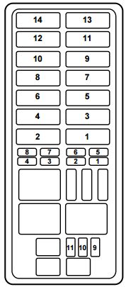
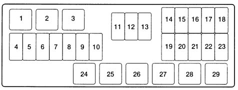
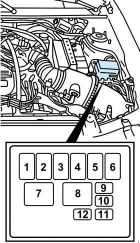
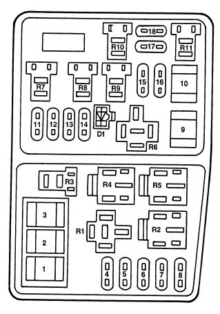
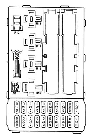
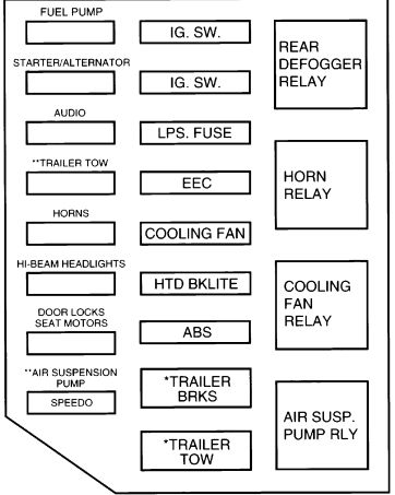
Fuse box under the bonnet
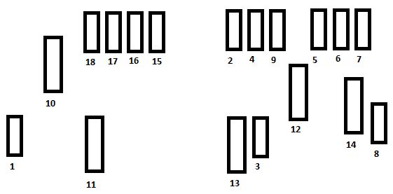
| Fuse | Ampere rating [A] | Function |
| 1 | 20 | Water-in-diesel-fuel sensor |
| 2 | 15 | Horn |
| 3 | 10 | Screen wash |
| 4 | 20 | Headlamp wash |
| 5 | 15 | Fuel pump |
| 6 | 10 | Power steering |
| 7 | 10 | Coolant level sensor |
| 8 | 25 | Starter |
| 9 | 10 | ECUs (ABS, ESP) |
| 10 | 30 | Engine control actuators (Ignition coil, Electrovalve, Oxygen sensor, Injection), canister purge |
| 11 | 40 | Air blower |
| 12 | 30 | Windscreen wiper |
| 14 | 30 | Air pump (petrol version) – Diesel fuel heater |
WARNING: Terminal and harness assignments for individual connectors will vary depending on vehicle equipment level, model, and market