Dodge Ram 3500 (2013 – 2018) – fuse box diagram
Year of production: 2013, 2014, 2015, 2016, 2017, 2018
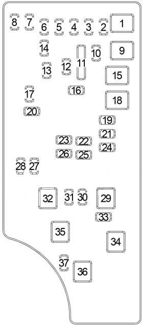
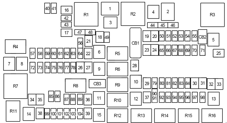
Engine Compartment Fuse Box (Power Distribution Center)
| No. |
A |
Protected Component |
| 1 | 80 | except for 5.7L: Radiator Fan Control Module |
| 2 | – | – |
| 3 | 60 | Radiator Fan High Relay |
| 4 | – | – |
| 5 | 40 | Compressor for Air Suspension |
| 6 | 40 | Antilock Brakes/Electronic Stability Control Pump |
| 7 | 40 | Starter Solenoid |
| 8 | 20 | Emissions Diesel |
| 9 | 40 | 6.7L Cummins: Fuel Heater |
| 30 | 3.0L EcoDiesel: Fuel Heater | |
| 10 | 40 | Body Control Module (BCM) (Exterior Lighting No.2) |
| 50 | with Stop/Start: Body Control Module (BCM) (Exterior Lighting No.2) | |
| 11 | 30 | Integrated Trailer Brake Module |
| 12 | 40 | Body Control Module (BCM) (Interior Lights) |
| 13 | 40 | Blower Motor |
| 14 | 40 | Body Control Module (BCM) (Power Locks) |
| 15 | 30 | Electric Park Brake Right Side |
| 16 | 30 | Smart Bar |
| 17 | – | – |
| 18 | – | – |
| 19 | 30 | 6.7L Cummins: Selective Catalytic Reduction (SCR) |
| 20 | 3.0L EcoDiesel (’16-’18): Selective Catalytic Reduction (SCR) | |
| 20 | 30 | Passenger Door Module |
| 21 | 30 | Drive Train Control Module |
| 22 | 20 | except for 3.0L EcoDiesel: Powertrain Control Module (PCM) |
| 30 | 6.7L Cummins (’16-’18): Powertrain Control Module (PCM) | |
| 23 | 30 | Body Control Module (BCM) |
| 24 | 30 | Driver Door Module |
| 25 | 30 | Front Wiper (Low Speed/High Speed) |
| 26 | 30 | Antilock Brakes/Stability Control Module (Valves) |
| 27 | – | – |
| 28 | 20 | Trailer Tow (Back-Up Lights) |
| 29 | 20 | Trailer Tow (Parking Lights) |
| 30 | 30 | Trailer Tow Receptacle |
| 31 | 30 | 3.0L EcoDiesel: Heater Control Module |
| 20 | 3.0L EcoDiesel: Heater Control Module | |
| 32 | 30 | Drive Train Control Module |
| 33 | 20 | 6.7L Cummins: Transmission Control Module, Fuel Heater No.1, Rear Blower |
| 20 | Rear Blower | |
| 34 | 30 | Vehicle System Interface Module No.2 |
| 35 | 30 | Sunroof |
| 36 | 30 | Rear Window Defroster |
| 37 | 30 | 6.7L Cummins: Fuel Heater No.2 |
| 38 | 30 | Power Inverter 115V AC |
| 39 | 30 | ’14-’15: Vehicle System Interface Module No.1 |
| 20 | Special Services (’16-’18): Power Outlet | |
| 40 | – | – |
| 41 | 10 | Active Grill Shutter |
| 42 | 20 | Horn |
| 43 | 10 | Snow Plow (Left) |
| 44 | 10 | Diagnostic Connector |
| 45 | – | – |
| 46 | 10 | Tire Pressure Module, Upfitter |
| 47 | 10 | Snow Plow (Right) |
| 48 | – | – |
| 49 | 10 | Instrument Panel Cluster |
| 50 | 20 | Air Suspension Control Module |
| 51 | 10 | Keyless Ignition Node Module, Radio Frequency Hub Module |
| 52 | 5 | Intelligent Battery Sensor |
| 53 | 20 | Trailer Tow – Left Turn/Stop Lights |
| 54 | 20 | Adjustable Pedals |
| 55 | 20 | Left/Right Spot |
| 56 | 15 | Diesel: Additional Diesel Content |
| 57 | 20 | Transmission Control Module (8 Speed Automatic Transmission), Powertrain Module Relay (6 Speed Automatic Transmission) |
| 58 | 20 | Gasoline (’14-’15): Engine Cooling Pump |
| 25 | 6.7L Cummins (’14-’15): Engine Cooling Pump | |
| 59 | 10 | ’16-’18: Selective Catalytic Reduction (SCR) Relay |
| 60 | 15 | Underhood Lamp |
| 61 | 20 | ’14-’15: Power Take-off Unit |
| 10 | Diesel (’16-’18): PM Sensor | |
| 62 | 10 | Air Conditioning Clutch |
| 63 | 20 | Gasoline: Ignition Coils |
| 20 | 6.7L Cummins: Urea Heater | |
| 64 | 25 | Fuel Injectors, Powertrain Control Module (PCM) |
| 65 | 10 | ’14-’15: USB interface |
| 66 | 10 | Sunroof Control Module, Passenger Window Switches, Rain Sensor |
| 67 | 10 | CD/DVD/Bluetooth Hands-free Module |
| 68 | – | – |
| 69 | 15 | 6.7L Cummins: Selective Catalytic Reduction (SCR) Module |
| 70 | 30 | Fuel Pump Motor |
| 71 | 25 | Audio Amplifier |
| 72 | 10 | ’14-’15: Voltage Stabilizer Modules |
| 10 | ’16-’18: Powertrain Control Module (PCM) | |
| 73 | 20 | HD: Fuel Transfer Pump |
| 74 | 20 | Gasoline, 3.0L EcoDiesel: Brake Vacuum Pump |
| 10 | 6.7L Cummins (’14-’15): Brake Vacuum Pump | |
| 75 | 10 | 3.6L & 5.7L 8 Speed A/T: Coolant Temperature Valve Actuator |
| 76 | 10 | Antilock Brakes/Electronic Stability Control |
| 77 | 10 | Drivetrain Control Module, Front Axle Disconnect Module, Transmission Control Module (3500HD) |
| 78 | 10 | Powertrain Control Module (PCM), Electric Power Steering, Intake Air Diverter Valve (6.7L Cummins) |
| 79 | 15 | Clearance Lights |
| 80 | 10 | Universal Garage Door Opener, Compass Module |
| 81 | 20 | Trailer Tow Right Turn/Stop Lights |
| 82 | 10 | Steering Column Control Module, Cruise Control |
| 83 | – | – |
| 84 | 15 | Switch Bank, Instrument Cluster |
| 85 | 10 | Airbag Module |
| 86 | 10 | Airbag Module |
| 87 | 10 | Air Suspension Control Module, Trailer Tow Module, Steering Column Control Module |
| 88 | 15 | Instrument Panel Cluster |
| 10 | Instrument Panel Cluster | |
| 89 | – | – |
| 90 | 20 | Power Outlet (Rear seats), Customer Selectable |
| 91 | ||
| 92 | – | – |
| 93 | 20 | Cigar Lighter |
| 94 | 10 | SBW/Shifter, Transfer Case Module |
| 95 | 10 | Rear Camera, Park Assist, License Lamps |
| 96 | 10 | Rear Seat Heater Switch |
| 97 | 25 | Rear Heated Seats, Heated Steering Wheel |
| 98 | 25 | Front Heated Seats |
| 99 | 10 | A/C Heater Module, In-Car Temperature Sensor, Himidity Sensor |
| 100 | 10 | Upfitters |
| 101 | 15 | Electrochromatic Mirror, Smart High Beams |
| 102 | – | – |
| 103 | – | – |
| 104 | 20 | Power Outlets (Instrument Panel/Center Console) |
| Circuit Breaker | ||
| CB1 | 25 | Power Window, Power Door Lock, Power Sliding Backlite Switch |
| CB2 | 25 | Driver Power Seat, Memory Seat Module |
| CB3 | 25 | Passenger Power Seat |
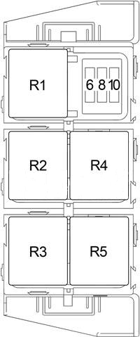
| Relay | ||
| R1 | Radiator Fan (Low Speed) | |
| R2 | Radiator Fan (High Speed) | |
| R3 | Air Suspension | |
| R4 | Selective Catalytic Reduction (SCR) | |
| R5 | Auto Shut Down (Powertrain Control Module) |
|
| R6 | Ignition (Run/Accessory No.1) | |
| R7 | Starter | |
| R8 | Ignition (Run/Start) | |
| R9 | Fuel Heater (No.1) | |
| Air Pump (No.2) | ||
| R10 | EBL | |
| R11 | – | |
| R12 | Ignition (Run/Only No.2) | |
| R13 | Frame Heater | |
| R14 | Ignition (Run/Accessory No.2) | |
| R15 | Ignition (Run/Only No.1) | |
| R16 | Blower Motor | |
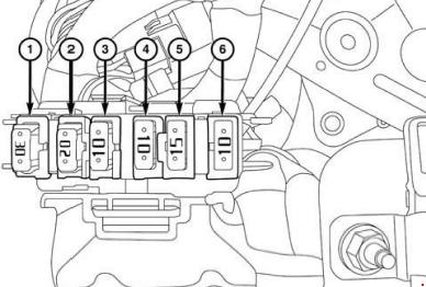
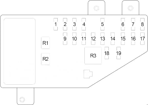
Additional Fuse Box

| No. |
A |
Protected Component |
| 1 | 30 | Auxiliary Switch Bank Module (ASBM), HVAC, Integrated Center Stack (ICS) |
| 2 | 20 | Integrated Trailer Brake Module (ITBM) |
| 3 | 10 | Parktronics (PTS) |
| 4 | 10 | Body Control Module (BCM), Cluster – Exterior Lighting Feeds |
| 5 | 15 | Spare |
| 6 | 10 | Radio with Built in Amplifier |
WARNING: Terminal and harness assignments for individual connectors will vary depending on vehicle equipment level, model, and market.