Chevrolet Avalanche (2007) – fuse box diagram
Year of production: 2007
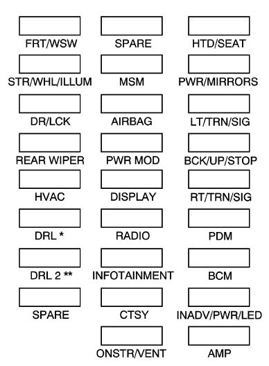
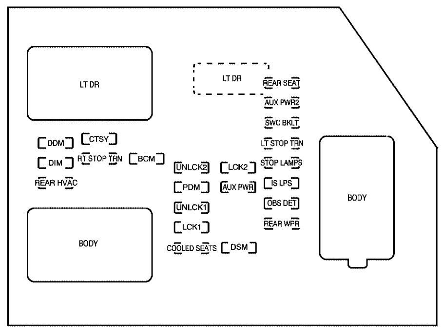
Instrument Panel Fuse Block
The instrument panel fuse block access door is located on the driver side edge of the instrument panel.
| Fuses | Usage |
| LT DR | Driver’s Side Power Window Circuit Breaker |
| REAR SEAT | Rear Seats |
| AUX PWR2 | Rear Cargo Area Power Outlets |
| SWC BKLT | Steering Wheel Controls Backlight |
| DDM | Driver Door Module |
| CTSY | Dome Lamps, Driver’s Side Turn Signal |
| LT STOP TRN | Driver’s Side Turn Signal, Stoplamp |
| DIM | Instrument Panel Back Lighting |
| RT STOP TRN | Passenger’s Side Turn Signal, Stoplamp |
| BCM | Body Control Module |
| UNLCK2 | Power Door Lock 2 (Unlock Feature) |
| LCK2 | Power Door Lock 2 (Lock Feature) |
| STOP LAMPS | Stoplamps, Center-High Mounted Stoplamp |
| REAR HVAC | Rear Climate Controls |
| PDM | Passenger Door Module, Universal Home Remote System |
| AUX PWR | Accessory Power Outlets |
| IS LPS | Interior Lamps |
| UNLCK1 | Power Door Lock 1 (Unlock Feature) |
| OBS DET | Ultrasonic Rear Parking Assist, Power Liftgate |
| LCK1 | Power Door Lock 1 (Lock Feature) |
| REAR WPR | Rear Wiper |
| COOLED SEATS | Not Used |
| DSM | Driver Seat Module, Remote Keyless Entry System |
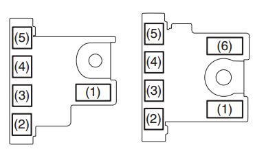
| Harness connector | Usage |
| LT DR | Driver Door Harness Connection |
| BODY | Harness Connector |
| BODY | Harness Connector |
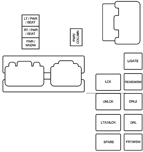
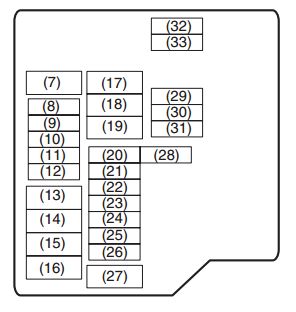
Center Instrument Panel Fuse Block
The center instrument panel fuse block is located underneath the instrument panel, to the left of the steering column.
Top View
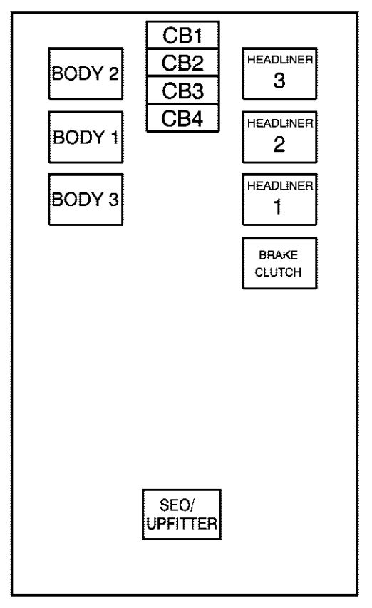
fuse box diagram –
center instrument panel (top view)
| Harness connector | Usage |
| BODY 2 | Body Harness Connector 2 |
| BODY 1 | Body Harness Connector 1 |
| BODY 3 | Body Harness Connector 3 |
| HEADLINER 3 | Headliner Harness Connector 3 |
| HEADLINER 2 | Headliner Harness Connector 2 |
| HEADLINER 1 | Headliner Harness Connector 1 |
| BRAKE CLUTCH | Brake Clutch Harness Connector |
| SEO/UPFITTER | Special Equipment Option Upfitter Harness Connector |
| Circuit breaker | Usage |
| CB1 | Passenger’s Side Power Window Circuit Breaker |
| CB2 | Passenger’s Seat Circuit Breaker |
| CB3 | Driver’s Seat Circuit Breaker |
| CB4 | Not Used |
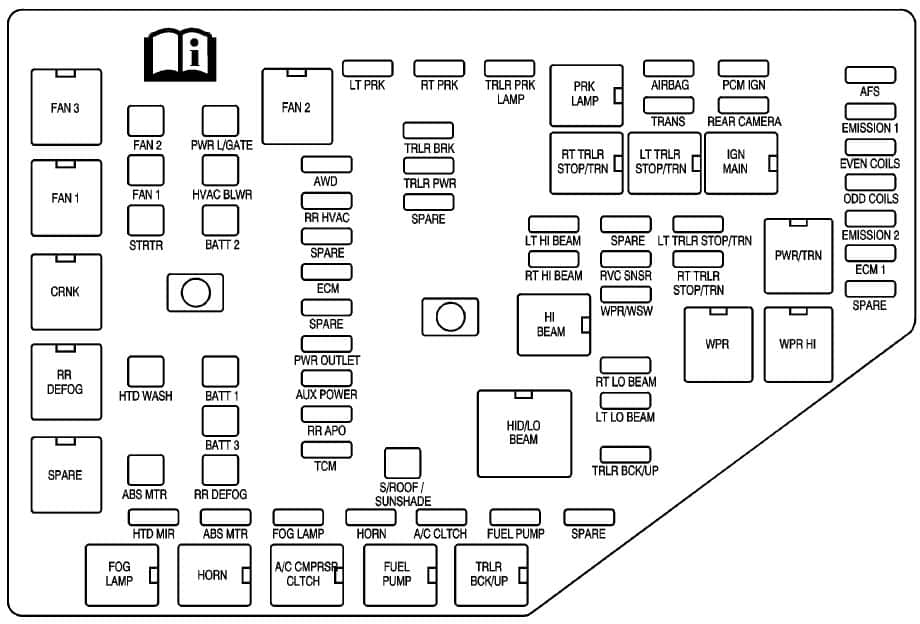
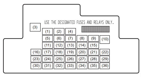
Underhood Fuse Block
The underhood fuse block is located in the engine compartment, on the driver side of the vehicle. Lift the cover for access to the fuse/relay block.

| Fuses | Usage |
| 1 | Not Used |
| 2 | Electronic Stability Suspension Control, Automatic Level Control Exhaust |
| 3 | Left Trailer Stop/Turn Lamp |
| 4 | Engine Controls |
| 5 | Engine Control Module, Throttle Control |
| 6 | Right Trailer Stop/Turn Lamp |
| 7 | Front Washer |
| 8 | Oxygen Sensors |
| 9 | Antilock Brakes System 2 |
| 10 | Trailer Back-up Lamps |
| 11 | Driver Side Low-Beam Headlamp |
| 12 | Engine Control Module (Battery) |
| 13 | Fuel Injectors, Ignition Coils (Right Side) |
| 14 | Transmission Control Module (Battery) |
| 15 | Vehicle Back-up Lamps |
| 16 | Passenger Side Low-Beam Headlamp |
| 17 | Air Conditioning Compressor |
| 18 | Oxygen Sensors |
| 19 | Transmission Controls (Ignition) |
| 20 | Fuel Pump |
| 21 | Not Used |
| 22 | Rear Washers |
| 23 | Fuel Injectors, Ignition Coils (Left Side) |
| 24 | Trailer Park Lamps |
| 25 | Driver’s Side Park Lamps |
| 26 | Passenger’s Side Park Lamps |
| 27 | Fog Lamps |
| 28 | Horn |
| 29 | Passenger Side High-Beam Headlamp |
| 30 | Daytime Running Lamps |
| 31 | Driver Side High-Beam Headlamp |
| 32 | Not Used |
| 33 | Sunroof |
| 34 | Key Ignition System, Theft Deterrent System |
| 35 | Windshield Wiper |
| 36 | SEO B2 Upfitter Usage (Battery) |
| 37 | Electric Adjustable Pedals |
| 38 | Climate Controls (Battery) |
| 39 | Airbag System (Ignition) |
| 40 | Amplifier |
| 41 | Audio System |
| 42 | Four-Wheel Drive |
| 43 | Miscellaneous (Ignition), Rear Vision Camera, Cruise Contro |
| 44 | Liftgate Release |
| 45 | OnStar®, Rear Seat Entertainment Display |
| 46 | Instrument Panel Cluster |
| 47 | Not Used |
| 48 | Not Used |
| 49 | Auxiliary Climate Control (Ignition), Compass-Temperature Mirror |
| 50 | Rear Defogger |
| 51 | Airbag System (Battery) |
| 52 | SEO B1 Upfitter Usage (Battery) |
| 53 | Cigarette Lighter, Auxiliary Power Outlet |
| 54 | Automatic Level Control Compressor Relay, SEO Upfitter Usage |
| 55 | Climate Controls (Ignition) |
| 56 | Engine Control Module, Secondary Fuel Pump (Ignition) |
| J-Case Fuses | Usage |
| 60 | Cooling Fan 1 |
| 61 | Automatic Level Control Compressor |
| 62 | Heavy Duty Anti-lock Brake System |
| 63 | Cooling Fan 2 |
| 64 | Anti-lock Brake System 1 |
| 65 | Starter |
| 66 | Stud 2 (Trailer Brakes) |
| 67 | Left Bussed Electrical Center 1 |
| 68 | Electric Running Boards |
| 69 | Heated Windshield Washer System |
| 70 | Four-Wheel Drive System |
| 71 | Stud 1 (Trailer Connector Battery Power) |
| 72 | Mid-Bussed Electrical Center 1 |
| 73 | Climate Control Blower |
| 74 | Power Liftgate Module |
| 75 | Left Bussed Electrical Center 2 |
| Relays | Usage |
| FAN HI | Cooling Fan High Speed |
| FAN LO | Cooling Fan Low Speed |
| ENG EXH VLV | Not Used |
| FAN CNTRL | Cooling Fan Control |
| HDLP LO/HID | Low-Beam Headlamp |
| FOG LAMP | Front Fog Lamps |
| A/C CMPRSR | Air Conditioning Compressor |
| STRTR | Starter |
| PWR/TRN | Powertrain |
| FUEL PMP | Fuel Pump |
| PRK LAMP | Parking Lamps |
| REAR DEFOG | Rear Defogger |
| RUN/CRANK | Switched Power |
WARNING: Terminal and harness assignments for individual connectors will vary depending on vehicle equipment level, model, and market.