Dodge Challenger RT/SRT (from 2008)- fuse box diagram

Dodge Challenger RT/SRT – fuse box diagram

Year of production: 2008, 2009, 2010, 2011, 2012, 2013, 2014, 2015, 2016

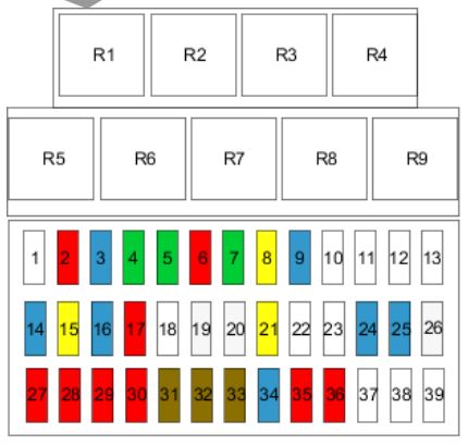
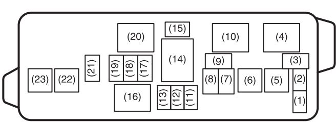
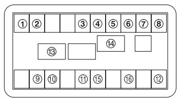
SRT8 Integrated power module (front engine bay)
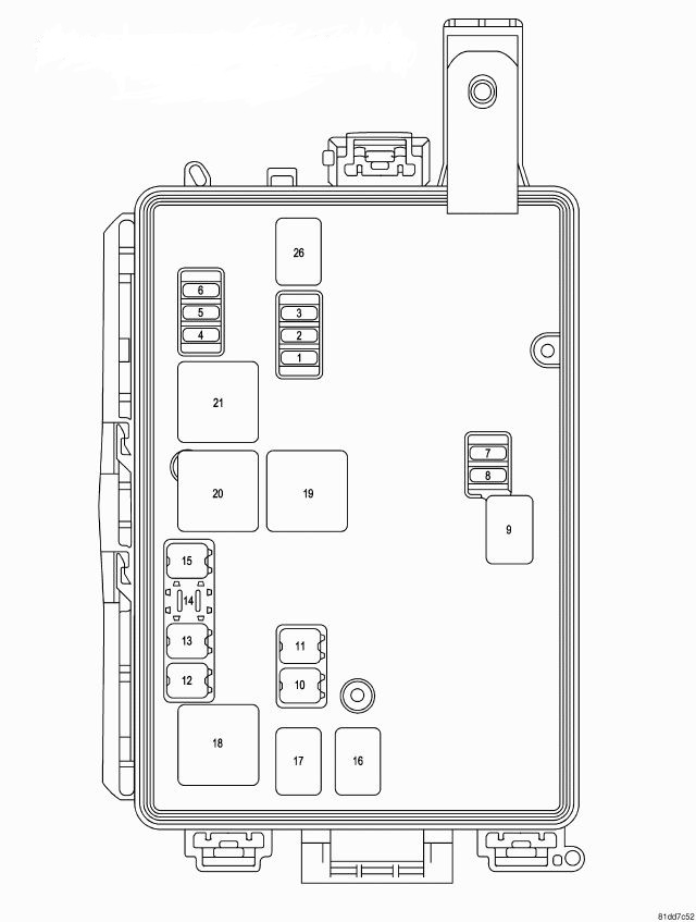
Dodge Challenger RT/SRT Third Generation - integrated power module
Dodge Challenger RT/SRT Third Generation – integrated power module
Cavity Cartridge fuse [A] Mini-fuse [A] Description
1 15 Blue Washer Motor
2 25 Neutral Powertrain Control Module (PCM)
3 25 Neutral Ignition Run/Start
4 25 Neutral Alternator
5
6 25 Neutral Ignition Coils/Injectors
7
8 25 Neutral Starter
9
10 30 Pink Windshield Wiper
11 30 Pink Anti-lock Brake System (ABS) Valves
12 40 Green Radiator fan
13 50 Red Anti-lock Brake System (ABS) Pump Motor
14
15 50 Red Radiator fan
16
17
18
19
20
21
22

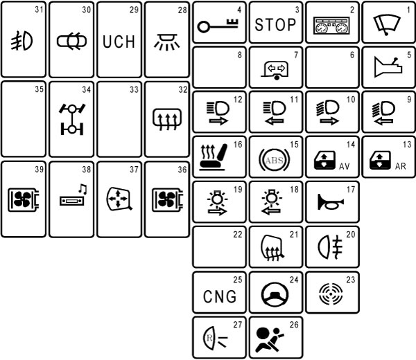
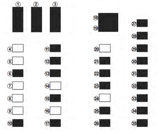
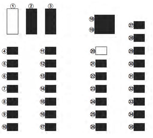
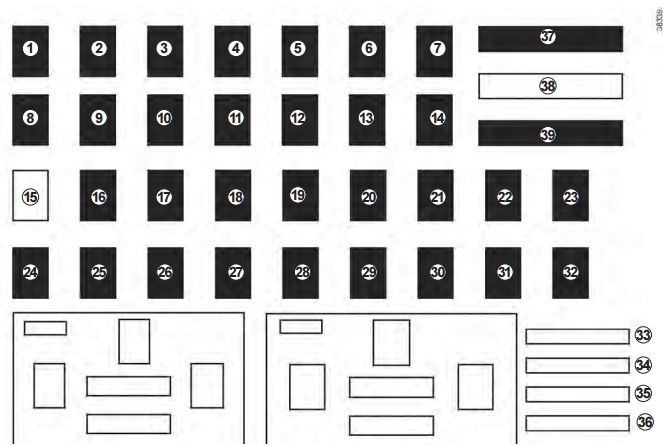
Rear power distribution center  fuses – RT/SRT (trunk area)
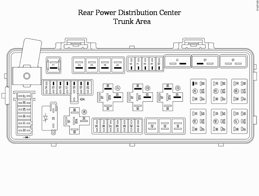
Dodge Challenger RT/SRT Third Generation - fuse box - rear power distribution - ceneter trunk area
Dodge Challenger RT/SRT Third Generation – fuse box – rear power distribution – ceneter trunk area
Cavity Cartridge fuse [A] Mini fuse [A] Description
1 60 Yellow Ignition Off Draw (IOD)
2 40 Green Integrated Power Module (IPM)
3
4 40 Green Integrated Power Module (IPM)
5 30 Pink Heated Seats – if equipped
6 20 Yellow Fuel Pump
7 20 Yellow Sub Amp – if equipped
8 15 Blue Diagnostic Link Connector (DLC)/Wireless Ignition Node (WIN)
9 20 Yellow Power Outlet
10
11*
12*
13*
14 10 Red AC Heater Control/Cluster/Security Module – if equipped
15 20 Yellow
16 20 Yellow
17 20 Yellow Cluster
18 20 Yellow Selectable Power Outlet
19 10 Red Stop Lights
20
21
22
23
24
25
26
27 10 Red Occupant Restraint Controller (ORC)
28 10 Red Ignition Run
29 5 Orange Cluster/Electronic Stability Program (ESP)/Powertrain Control Module (PCM)/STOP LIGHT Switch
30 10 Red Door Modules/Power Mirrors/Steering Control Module (SCM)
31
32
33
34
35 5 Orange Antenna Module – if equipped/Power Mirrors/Rain Sensor – if equipped
36 20 Yellow Hands-Free Phone – if equipped/Video Monitor – if equipped/Radio
37 15 Blue Transmission
38 10 Red Cargo Light/Vehicle Information Module – if equipped
39 10 Red Heated Mirrors – if equipped
40 5 Orange Auto Inside Rearview Mirror/Heated Seats – if equipped/Switch Bank
41 10 Red AC Heater Control/Headlights/Park Assist – if equipped/Tire Pressure Monitoring – if equipped/Occupant Restraint Controller (ORC)
42 30 Pink Front Blower Motor
43 30 Pink Rear Window Defroster
44 20 Blue Amplifier – if equipped/Sunroof – if equipped


The Cluster (without power memory seat), the Driver Seat Switch (with power memory seat), and the Memory Module
(if equipped) are fused by the 25 amp circuit breaker in Cavity 11.

The Passenger Seat Switch is fused by the 25 amp circuit breaker in Cavity 12. The Door Modules (except base), the
Driver Door Lock Switch (base), the Driver Express Power Window Switch (if equipped), and the Passenger Door

Lock Switch (base) are fused by the 25 amp circuit breaker in Cavity 13.


WARNING: Terminal and harness assignments for individual connectors will vary depending on vehicle equipment level, model, and market.

Dodge Challenger (2008 – 2010) – fuse box diagram

Dodge Challenger (2008 – 2010) – fuse box diagram

Year of  production: 2008, 2009, 2010

Integrated power module (IPM)

Cavity Cartridge fuse Mini Fuse Description
1 15 Blue Washer motor
2 25 Natural Powertrain Control Module (PCM)
3 25 Natural Ignition Run/Start
4 25 Natural EGR Solenoid/ Alternator
5
6 25 Natural Ignition Coils/Injectors
7 25 Natural Headlamp Washer Relay – If Equipped
8 30 Green Starter
9
10 30 Pink Windshield Wiper
11 30 Pink Anti-Lock Brake System (ABS) Valves
12 40 Green Radiator Fan Lo/High
13 50 Red Anti-Lock Brake System (ABS) Pump Motor
14
15 50 Red Radiator Fan
16
17
18
19
20
21
22

Rear power distribution center

Cavity Cartridge fuse Mini fuse Description
1 60 Yellow Ignition Off Draw (IOD) Cavity 1 of the Rear Power Distribution Center contains a black IOD fuse needed for vehicle processing during assembly. The service replacement part is a 60 Amp yellow cartridge fuse.
2 40 Green Integrated Power Module (IPM)
3
4 40 Green Integrated Power Module (IPM)
5 30 Pink Heated Seats – If Equipped
6 20 Yellow Fuel Pump
7 15 Blue Sub Amp – If Equipped
8 15 Blue Diagnostic Link Connector (DLC)/Wireless Control Module (WCM)/ Wireless Ignition Node (WIN)
9 20 Yellow Power Outlet
10
11*
12*
13*
14 10 Red AC Heater Control/ Cluster/Security Module – If Equipped
15
16
17 20 Yellow Cluster
18 20 Yellow Selectable Power Outlet
19 10 Red Stop Lights
20
21
22
23
25
26
27 10 Red Occupant Restraint Controller (ORC)
28 10 Red Ignition Run, AC Heater Control/Occupant Restraint Controller (ORC)
29 5 Orange Cluster/Electronic Stability Program (ESP)/ Powertrain Control Module (PCM)/STOP LIGHT Switch
30 10 Red Door Modules/Power Mirrors/Steering Control Module (SCM)
31
32
33
34
35 5 Orange Antenna Module – If Equipped/Power Mirrors
36 25 Netural Hands-Free Phone – If Equipped/Radio/ Amplifier Feed
37 15 Blue Transmission
38 10 Red Cargo Light/Vehicle Information Module – If Equipped
39 10 Red Heated Mirrors – If Equipped
40 5 Orange Auto Inside Rearview Mirror/Heated Seats – If Equipped/Switch Bank
41
42 30 Pink Front Blower Motor
43 30 Pink Rear Window Defroster
44 20 Blue Amplifier/Sunroof – If Equipped

WARNING: Terminal and harness assignments for individual connectors will vary depending on vehicle equipment level, model, and market.

Renault Kangoo (1996 – 2006) – fuse box diagram

Renault Kangoo (1996 – 2006) – fuse box diagram

Year of production: 1996, 1997, 1998, 1998, 1999, 2000, 2001, 2002, 2003, 2004, 2005, 2006

Fuse box in passenger compartment

Renault Kangoo mk1 - fuse box diagram
Renault Kangoo mk1 – fuse box diagram
Fuse Ampere rating [A] Description
1 Not used
2 10 Heated mirror(s)
3 15 Transponder
4 30 No information available
5 30 Trailer connector
6 10 Transponder
7 30 Heated rear windscreen
8 20 Transponder control unit
9 15 Front fog lights
10 Not used
11 Not used
12 Not used
13 Not used
14 15 Speed sensor automatic clutch
15 20 Wash/wipe, front
16 15 Horn
17 10 Or
18 Not used
19 25 Window, left, front
20 25 Window, right, front
21 20 Heated seat(s)
22 Not used
23 Not used
24 15 Air conditioning
25 15 Telephone
26 25 Heating and ventilation
27 10 Main beam, left
28 10 Main beam, right
29 10 Left
30 10 Dipped beam, right
31 7,5 Heating
32 7,5 Switches
33 7,5 Rear fog light(s)
34 15 Horn
35 10 Direction indicators
36 10 Heated mirror(s)
37 Not used
38 Not used
39 Not used
Relay R1 Main relay
Relay R2 Fog light(s)
Relay R3 Fuel gauge
Relay R4 Central locking
Relay R5 Buzzer
Relay R6 Wash/wipe, rear
Relay R7 Flasher unit
Relay R8 Windows
Relay R9 Heated rear windscreen

WARNING: Terminal and harness assignments for individual connectors will vary depending on vehicle equipment level, model, and market.

Renault Espace – fuse box diagram

Renault Espace – fuse box diagram


Allocation of fuses

Symbol Allocation
Windscreen-washer Windscreen washer
Accessories-socket Third row accessories socket, boot accessories socket
Cigarette-lighter Front cigarette lighter, front and rear second row accessories socket
Heated-window Not used
Heated-door-mirror1 Heated door mirrors
Brake-lights Brake lights, passenger compartment central unit
PArking-brake Parking brake
Additional-servo Additional servo
Radio Radio, multifunction screen, multimedia accessories sockets, parking brake control
BCM Passenger compartment centre unit, rear wiper, rear fog light
Locking-opening-elements Locking opening elements, tailgate opening and closing control
SED Not used
Towbar-socket Towbar socket
DIAG Diagnostic socket, audio alarm
Horn Horn
instrument-panel1 Instrument panel, dashboard control lighting
Piloted-dampened-suspension Piloted dampened suspension
Windscreen-wiper Front windscreen wiper
Directions-indicators Direction indicator lights, hazard warning lights
USB Rear USB sockets on console
Window-open Not used

WARNING: Terminal and harness assignments for individual connectors will vary depending on vehicle equipment level, model, and market.

Renault Duster (2012) – fuse box diagram

Renault Duster (2012) – fuse box diagram

Year of production: 2012

Allocations of fuses in the passenger compartment

Renault Dubster fuse box diagram
Renault Duster fuse box diagram
Symbol Allocation
ABS ABS
Radio Radio
Brake-lights Brake lights
Air conditioning Air conditioning
Fog-lights Front fog lights
instrument-panel Instrument panel injection
Windscreen-wiper Windscreen wiper
Central-locking Central locking of doors and tailgate
Rear-screen-de-icing Rear screen de-icing
Not-used Not used
Horn Horn
Main-power-supply Main power supply
Heated-seats Heated seats
Heated-door-mirror Heated door mirrors
Electric-front-window Electric front windows
Interrior-lights Interior lighting
Electric-door-mirror Electric door mirror
Heating Heating
Directions Not used
Air-bag Air bag
Right-hand-main-beam Right-hand main beam headlight
Left-hand-main-beam Left-hand main beam headlight
Left-hand-dipped-beam Left-hand dipped beam headlight
Right-hand-dipped Right-hand dipped beam headlight
Right-hand-side-light Right-hand side light
Left-hand-side-light Left-hand side ligh
Rear-fog-light Rear fog light
Electric--rear-windows Electric rear windows
Engine-immobiliser Engine immobiliser
Reversing-light-and-rear Reversing light and rear screen wiper
Power-assisted-steering Power-assisted steering
Automatic-gearbox Automatic gearbox
GAS-fuel GAS fuel
4-wheel-drive-(4WD) 4-wheel drive (4WD) transmission


WARNING: Terminal and harness assignments for individual connectors will vary depending on vehicle equipment level, model, and market.

Renault Clio 4 (mk4) – fuse box diagram

Renault Clio 4 (mk4) – fuse box diagram


Fuse box

Vehicle is fitted with automatic windscreen wiper and automatic headlights

Renault Clio 4 (mk4) - fuse box - vehicle with automatic windscreen wiper and automatic headlights
Renault Clio 4 (mk4) – fuse box – vehicle with automatic windscreen wiper and automatic headlights
Fuse Allocation
1 Front windscreen wiper
2 Front left daytime running light, right side light, lefthand main beam headlight, right-hand dipped beam headlight
3 Interior lighting, registration plate lighting, fog light
4 Empty location
5 Empty location
6 Front right daytime running light, left side light, righthand main beam headlight, left-hand dipped beam headlight
7 Empty location
8 Empty location
9 Empty location
10 Steering column control
11 Door locking, rain and light sensor, steering wheel angle sensor, vehicle start button
12 Courtesy light, boot light, air-conditioning
13 ABS-ESC, brake switch
14 Empty location
15 Horn
16 Empty location
17 Cigarette lighter
18 Radio and multimedia, diagnostic socket
19 Power-assisted steering
20 Empty location
21 Empty location
22 Injection, start-up, fuel pump
23 Brake switch
24 Empty location
25 Headlight beam height adjustment, rear screen, heating, parking distance control, cruise control, radio, heated seat, seat belt alert
26 Automatic gearbox
27 Reversing light, rear wiper, passenger compartment ECU
28 Instrument panel
29 Steering column control, additional equipment
30 Air conditioning
31 Front and rear wipers, reversing light
32 Central locking of opening elements
33 Direction indicator lights
34 Passenger compartment ECU, hands-free access
35 Courtesy light, electric windows, air conditioning, electric wing mirrors, stop lights, ABS

Others vehicles

Renault Clio 4 (mk4) - fuse box - others vehicles
Renault Clio 4 (mk4) – fuse box – others vehicles
Number Allocation
1 Empty location
2 Front fog lights
3 Wipers
4 Right-hand side lights
5 Left-hand side lights
6 Right-hand dipped beam headlight
7 Left-hand dipped beam headlight
8 Right-hand main beam headlight
9 Left-hand main beam headlight
10 Steering column control
11 Rear electric windows, steering wheel angle sensor, vehicle start button
12 Courtesy light, boot light, air-conditioning
13 ABS-ESC, brake switch
14 Steering column control
15 Horn
16 Rear fog lights
17 Cigarette lighter
18 Radio and multimedia, diagnostic socket
19 Power-assisted steering
20 Empty location
21 Airbag, electric steering column lock
22 Injection, start-up, fuel pump
23 Brake switch
24 Daytime running lights
25 Headlight beam height adjustment, rear screen, heating, parking distance control, cruise control, radio, heated seat, seat belt alert
26 Automatic gearbox
27 Reversing light, rear wiper, passenger compartment ECU
28 Instrument panel
29 Steering column control, additional equipment
30 Air conditioning
31 Front and rear wipers, reversing light
32 Central locking of opening elements
33 Direction indicator lights
34 Passenger compartment ECU, hands-free access
35 Courtesy light, electric windows, air conditioning, electric wing mirrors, stop lights, ABS


WARNING: Terminal and harness assignments for individual connectors will vary depending on vehicle equipment level, model, and market.

Ranault Capture (from 2013) – fuse box diagram

Ranault Capture (from 2013) – fuse box diagram


Fuse box

Renault Capture - fuse box diagram
Renault Capture – fuse box diagram
Fuse Allocation
1 Power-assisted steering
2 Injection
3 Airbag
4 Automatic gearbox, LPG
5 Dipped beam headlights
6 Front fog lights, front side lights, main beam headlights
7 Horn
8 Left-hand main beam headlight
9 Right-hand main beam headlight
10 Right-hand dipped beam headlight
11 Left-hand dipped beam headlight
12 Left-hand side lights
13 Right-hand side lights
14 Rear windscreen wiper
15 Empty location
16 Headlight beam adjustment
17 Daytime running lights
18 Brake lights
19 Electric door mirrors
20 ABS, ESP
21 Interior lighting
22 Vehicle On/Off button
23 Radio
24 Passenger compartment ECU
25 Passenger compartment ECU
26 Direction indicator lights
27 Central locking of opening elements
28 UCE energy management
29 UCE energy management
30 Alarm
31 Instrument panel
32 Cigarette lighter
33 Rear fog lights
34 Front seat heating
35 Rear screen de-icer
36 Towbar
37 Front windscreen wiper
38 Empty location
39 Front windscreen wiper

WARNING: Terminal and harness assignments for individual connectors will vary depending on vehicle equipment level, model, and market.

Maruti Suzuki Alto K10 (2nd Generation – second generation) – fuse box diagram

Maruti Suzuki Alto K10 (2nd Generation – second generation) – fuse box diagram

Fuses

Vehicle has three type od fuse:

  • Main fuse –  takes current directly from the battery
  • Promary fuses – are between the main fuse and individual fuses, and are for electrical load groups
  • Individual fuses are individual electrical circuits. To remove a fuse, use the fuse puller provide in the fuse box

Fuses in the engine compartment

Suzuki Alto 800 2nd generation (second generation) - fuse box - engine compartment
Maruti Suzuki Alto K10 2nd generation (second generation) – fuse box – engine compartment
Fuse Ampere rating [A] Description
(1) Blank
(2) Blank
(3) 10 Font fog light
(4) A/C compressor relay
(5) 50 Ingnition switch fuse
(6) 50 Battery1
(7) 15 Headlight (left) fuse
(8) 15 Headlight (right) fuse
(9) Blank
(10) Radiator fan relay
(11) Blank
(12) Blank
(13) Blank
(14) 80 All electric load
(15) Blank
(16) Main relay
(17) 30 Radiator fan fuse
(18) 15 Fuel injection fuse
(19) 10 A/C compressor fuse
(20) Fuel pump relay
(21) 7,5 Automated Manual Transaxle (if equipped)
(22) 40 Automated Manual Transaxle pump (if equipped)
(23) 30 Battery 2

Fuses under the dash board

Suzuki Alto 800 2nd Generation (Second generation) - fuse box - passeneger compartment
Maruti Suzuki Alto K10 2nd Generation (Second generation) – fuse box – passeneger compartment
Fuse Ampere rating [A] Description
(1) 10 IG2 SIG
(2) 15 Wiper
(3) Blank
(4) 7,5 Automated Manual Transaxle 2 (if equipped)
(5) 30 Blower motor
(6) 10 Stop light
(7) 10 Tail light
(8) 15 Audio
(9) 20 Door lock
(10) Blank
(11) 15 Accessory
(12) Blank
(13) 30 Power window
(14) 15 Ignition switch
(15) 10 Turn signal light
(16) 10 Meter
(17) 7,5 Air bag
(18) 7,5 IG1 SIG
(19) Blank
(20) Blank
(21) 30 Power steering
(22) 30 ST SIG
(23) 15 Horn/Hazard

WARNING: Terminal and harness assignments for individual connectors will vary depending on vehicle equipment level, model, and market.

Maruti Suzuki Alto 800 (2nd Generation – second generation) – fuse box diagram

Maruti Suzuki Alto 800 (2nd Generation – second generation) – fuse box diagram

Fuses

Vehicle has three type od fuse:

  • Main fuse –  takes current directly from the battery
  • Promary fuses – are between the main fuse and individual fuses, and are for electrical load groups
  • Individual fuses are individual electrical circuits. To remove a fuse, use the fuse puller provide in the fuse box

Fuses in the engine compartment

Suzuki Alto 800 2nd generation (second generation) - fuse box - engine compartment
Maruti Suzuki Alto 800 2nd generation (second generation) – fuse box – engine compartment


Fuse Ampere rating [A] Description
(1) Blank
(2) Blank
(3) Blank
(4) Blank
(5) 50 Ingnition switch fuse
(6) 50 Battery1
(7) 15 Headlight (left) fuse
(8) 15 Headlight (right) fuse
(9) Blank
(10) Radiator fan relay
(11) Blank
(12) Blank
(13) Blank
(14) 80 All electric load
(15) Blank
(16) Main relay
(17) 30 Radiator fan fuse
(18) 15 Fuel injection fuse
(19) 10 A/C compressor fuse
(20) Blank
(21) Blank
(22) Blank
(23) Blank


Fuses under the dash board

Suzuki Alto 800 2nd Generation (Second generation) - fuse box - passeneger compartment
Maruti Suzuki Alto 800 2nd Generation (Second generation) – fuse box – passeneger compartment
Fuse Ampere rating [A] Description
(1) 10 IG2 SIG
(2) 15 Wiper
(3) Blank
(4) Blank
(5) 30 Blower motor
(6) 10 Stop light
(7) 10 Tail light
(8) 15 Audio
(9) 20 Door lock
(10) Blank
(11) 15 Accessory
(12) Blank
(13) 30 Power window
(14) 15 Ignition switch
(15) 10 Turn signal light
(16) 10 Meter
(17) 7,5 Air bag
(18) Blank
(19) Blank
(20) Blank
(21) 30 Power steering
(22) 20 ST SIG
(23) 15 Horn/Hazard

WARNING: Terminal and harness assignments for individual connectors will vary depending on vehicle equipment level, model, and market.

Maruti Suzuki Alto 800 (1st generation – first generation – 2012) (CNG) – fuse box diagram

Maruti Suzuki Alto 800 (1st generation – first generation – 2010 – 2012) (CNF) – fuse box diagram

Fuses in the engine compartment

Suzuki Alto 800 - fuse box - engine compartment
Maruti Suzuki Alto 800 CNG – fuse box – engine compartment
Fuse Ampere rating [A] Description
(1) Blank
(2) Blank
(3) Blank
(4) Air compressor relay
(5) 50 Ignition switch fuse
(6) 50 Light
(7) 15 Headlight (left) fuse
(8) 15 Headlight (right) fuse
(9) Blank
(10) Radiator fan relay
(11) Blank
(12) Blank
(13) Blank
(14) 80 All electric load
(15) Blank
(16) Main relay
(17) 30 Radiator fan fuse
(18) 15 Fuel injection fuse
(19) 10 Air compressor fuse
(20) Fuel pump relay
(21) Blank
(22) Blank
(23) Blank

Fuses under the dash board

Suzuki Alto 800 CNG - fuse box - passenegr compartment
Maruti Suzuki Alto 800 CNG – fuse box – passenegr compartment
Fuse Ampere rating [A] Description
(1) Blank
(2) 20 Door lock
(3) 15 Audio
(4) 10 Tail light
(5) 10 Stop light
(6) 30 Blower motor
(7) Blank
(8) Blank
(9) 15 Wiper
(10) 10 IG2 SIG
(11) 30 Power window
(12) Blank
(13) 15 Accessory
(14) 15 Horn/Hazard
(15) 7,5 CNG Valve
(16) 7,5 CNG

WARNING: Terminal and harness assignments for individual connectors will vary depending on vehicle equipment level, model, and market.