Audi S1 (2010 – 2018) – fuse box diagram 

Audi S1 (2010 – 2018) – fuse box diagram

Year of production: 2010, 2011, 2012, 2013, 2014, 2015, 2016, 2017, 2018

Location

Audi A1 - fuse box diagram - location
Audi S1 – fuse box diagram – location
  1. Fuse holder D -SD-
  2. Fuse holder A -SA-
  3. Fuse holder C -SC-
  4. Relay/fuse holder F -SF-
  5. Fuse holder B -SB-, Fuse holder H -SH-
  6. Fuse holder B -SB-

Fuse holder A -SA-

At battery positive terminal (for models with battery in luggage compartment only).

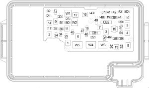
Audi A1 - fuse box diagram - fuse holder A-SA-
Audi S1 – fuse box diagram – fuse holder A-SA-
No. A Function/component
1 Vacant
2 110 Onboard supply
Engine component supply
3 Vacant

Fuse holder B -SB-

For models with battery in engine compartment

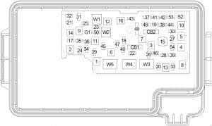
Audi A1 - fuse box diagram - fuse holder B-SB-
Audi S1 – fuse box diagram – fuse holder B-SB-

For models with battery in luggage compartment

Audi A1 - fuse box diagram - fuse holder B-SB-
Audi S1 – fuse box diagram – fuse holder B-SB-
No. A Function/component
1 175 Alternator -C-
2 40 Low heat output relay -J359-
Heater element for auxiliary air heater -Z35-
3 110 1) Onboard supply1)
Engine component supply1)
4 80 Power steering control unit -J500-
5 50 2)
40 3)
Radiator fan thermal switch -F18-
Radiator fan control unit -J293-
6 50 Automatic glow period control unit -J179-
7 60 High heat output relay -J360-
Battery monitor control unit -J3671)
Auxiliary heater element -Z35-
1) for models with battery in engine compartment only
2) no longer fitted, phased out (model year 2011)
3) phased-in modification (model year 2011)

Fuses in electronics box in fuse holder B -SB-/ Fuse holder H -SH-

In electronics box, in left engine compartment.
For S1 version models only, from January 2014
For models from November 2014 only.

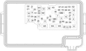
Audi A1 - fuse box diagram - fuses in electronics box in fuse holder B -SB-/ Fuse holder H -SH-
Audi S1 – fuse box diagram – fuses in electronics box in fuse holder B -SB-/ Fuse holder H -SH-
No. A Function/component
1 110 4)

5 5)

Onboard supply4)
Engine component supply4)
Radiator fan control unit -J293-5)
Radiator fan -V7-5)
2 250 Alternator -C-
Voltage regulator -C1-
3 Battery +
4 80 Power steering control unit -J500-
5 50 6) Automatic glow period control unit -J179-6)
Glow plug 1 -Q10-
Glow plug 2 -Q11-
Glow plug 3 -Q12-
Glow plug 4 -Q13-
6 50 7)

 8)
– 9)

Radiator fan control unit -J293-7)
Radiator fan -V7-7)
 7 125 Onboard supply8)
Engine component supply8)
4) for models with battery in engine compartment only, up to October 2014
5) for models from November 2014 only
6) for models with diesel engine only, from November 2014
7) for models up to October 2014
8) for models with battery in engine compartment only, from November 2014
9) Fuse 5 on fuse holder B -SB5- bridged, (see note)

Fuses in electronics box in fuse holder H -SH-

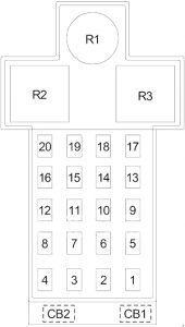
Audi A1 - fuse box diagram - fuses in electronics box in fuse holder H -SH-
Audi S1 – fuse box diagram – fuses in electronics box in fuse holder H -SH-
No. A Function/component
1 40 Heater element for auxiliary air heater -Z35-,
stage 1
2 30 Radiator fan control unit -J293-
Radiator fan -V7-
3 Vacant
4 40 Heater element for auxiliary air heater -Z35-,
stage 2
5 40 Heater element for auxiliary air heater -Z35-,
stage 3
6 30 Mechatronic unit for dual clutch gearbox -J743-
7 7.5 Engine control unit -J623-
8 20 Wiper motor switch-over relay 1 -J368-
Wiper motor switch-over relay 2 -J369-
9 5 Battery monitor control unit -J367-
10 10 Suppression filter -C24-
11 Vacant
12 10 12)
15 13)10)11)
Lambda probe heater -Z19-
Lambda probe 1 heater after catalytic converter -Z29-
13 5 Brake light switch -F-
Clutch position sender -G476-
14 13)
10 10)11)12)
Thermal switch for air conditioning system shut-off -F163-
Fuel metering valve -N290-
Oil pressure regulation valve -N428-
Cylinder head coolant valve -N489-
Coolant circulation pump -V50-
Circulation pump -V55-
Charge air cooling pump -V188-
Auxiliary heating pump -V488-
15 5 Onboard supply control unit -J519-, T52c/34
Engine control unit -J623-, T91/67;T94/…
Voltage stabiliser -J532-, T12aa/4
16 30 Starter motor -B-
17 15 12)13)
30 10)11)
Engine control unit -J623-
18 5 10)11)
10 12)13)
Oil level and oil temperature sender -G266-
Fuel pump relay -J17-
Radiator fan control unit -J293-
Low heat output relay -J359-
High heat output relay -J360-
Charge pressure control solenoid valve -N75-
Recirculation valve for turbocharger -N249-
Intake manifold flap valve -N316-
Oil pressure regulation valve -N428-
Cooling oil valve -N471-
19 7.5 10)
10 11)13)
20 12)
Engine component current supply relay -J757-
Fuel pressure regulating valve -N276-
Fuel metering valve -N290-
Injector 2 for cylinder 1 -N532-
Injector 2 for cylinder 2 -N533-
Injector 2 for cylinder 3 -N534-
Injector 2 for cylinder 4 -N535-
Actuator 1 for camshaft adjustment -F366-
Actuator 2 for camshaft adjustment -F367-
Actuator 3 for camshaft adjustment -F368-
Actuator 4 for camshaft adjustment -F369-
Actuator 5 for camshaft adjustment -F370-
Actuator 6 for camshaft adjustment -F371-
Actuator 7 for camshaft adjustment -F372-
Actuator 8 for camshaft adjustment -F373-
Vacuum pump for brakes -V192-
20 5 10)11)
10 13)
20 12)
Automatic glow period control unit -J179-
Exhaust flap control unit -J883-
Crankcase breather heater element -N79-
Activated charcoal filter solenoid valve 1 -N80-
Camshaft control valve 1 -N205-
Exhaust camshaft control valve 1 -N318-
Continued coolant circulation pump -V51-
Sender 1 for secondary air pressure -G609-
Sender 2 for secondary air pressure -G610-
10) for models with 1.4 l diesel engine only
11) for models with 1.6 l diesel engine only
12) for models with 1.0 l/1.4 l petrol engine only
13) for models with 1.8 l/2.0 l petrol engine only

Fuse holder C -SC-

Audi A1 - fuse box diagram - fuse holder C-SC-
Audi S1 – fuse box diagram – fuse holder C-SC-
No. A Function/component
Black
1 30 Digital sound package control unit -J525-
Voltage stabiliser -J532-
Radio -R-
2 40 Heater control unit -J65-
X-contact relief relay -J59-
Fresh air blower control unit -J126-
Fresh air blower -V2-
3 20 Cigarette lighter -U1-
12 V socket -U5-
4 15 Trailer detector control unit -J345-
5 5 Data bus diagnostic interface -J533-
6 30 Front passenger door control unit -J387-
Rear right door control unit -J389-
7 30 Driver door control unit -J386-
Rear left door control unit -J388-
8 30 Heated rear window relay -J9-
Heated rear window -Z1-
9 25 ABS control unit -J104-
10 20 Onboard supply control unit -J519-
11 15 High tone horn -H2-
Low tone horn -H7-
Horn relay -J413-
12 30 Onboard supply control unit -J519-
Brown
1 5 Alarm horn -H12-
Anti-theft alarm sensor -G578-
2 19)16)
7.5 14)15)17)18)20)
Terminal 30 voltage supply relay -J317-22)
Motronic current supply relay -J271-21)
Engine control unit -J623-
3 5 Onboard supply control unit -J519-
4 5

15 23)

ABS control unit -J104-
Voltage stabiliser 2 -J570-
All-wheel drive control unit -J492-23)
5 Vacant
6 5 Light/rain sensor -G397-
Aerial amplifier for mobile telephone -R86-
Telephone bracket -R126-
Front roof module -WX3-
7 15 21)
20 22)
Fuel pump control unit -J538- 21)
Fuel pump relay -J17- 22)
8 10 21) Auxiliary coolant pump relay -J496-, up to October 2014
9 5 Steering column electronics control unit -J527-
10 5 Light switch -E1-
11 10 Climatronic control unit -J255-
Air conditioning system control unit -J301-
Front passenger door control unit -J387- (up to April 2012)
Rear right door control unit -J389- (up to April 2012)
16-pin connector -T16-, diagnosis connection
12 10 Driver door control unit -J386- (up to April 2012)
Rear left door control unit -J388- (up to April 2012)
13 10 Onboard supply control unit -J519-
14 20 Relay for power sockets -J807-, for models without trailer socket only
15 30 Onboard supply control unit -J519-
16 20 Wiper motor switch-over relay 1 -J368-, up to October 2014
Engine component current supply relay -J757-23)24)
Ignition coil 1 with output stage -N70-23)24)
Ignition coil 2 with output stage -N127-23)24)
Ignition coil 3 with output stage -N291-23)24)
Ignition coil 4 with output stage -N292-23)24)
Red
1 19)20)
20 15)16)17)
Automatic glow period control unit -J179-
Vacuum pump for brakes -V192-
2 10

34)

Brake light switch -F- (up to October 2011)
brake pedal switch -F63- (up to October 2011)
auxiliary coolant pump relay -J496-
Lambda probe heater -Z19- (up to October 2011)
Lambda probe 1 heater after catalytic converter -Z29-, (up to October 2011)
Supply Fuse 9 on fuse holder F -SF9-, (from November 2011, up to October 2014)
Supply Fuse 10 on fuse holder F -SF10- (from November 2011, up to October 2014)
ABS control unit -J104-, from November 2011
3 18)19)20)
7.5 16)
15 14)15)17)
Air mass meter -G70-, up to October 2014
Fuel pump relay -J17-, up to October 2014
Low heat output relay -J359-, up to October 2014
High heat output relay -J360-, up to October 2014
Engine component current supply relay -J757-, up to October 2014
Fuel pressure regulating valve -N276-, up to October 2014
Coolant circulation pump -V50-, up to October 2014
4 15 14)15)17)16)
25 18)
30 19)20)
Engine control unit -J623-
Clutch position sender -G476-, up to October 2011
Brake light switch -F-, up to October 2011
5 20 18)
15 19)20)
20 14)15)17)
30 16)
Ignition coil 1 with output stage -N70-, up to October 2014
Ignition coil 2 with output stage -N127-, up to October 2014
Ignition transformer -N152-, up to October 2014
Fuel pressure regulating valve -N276-, up to October 2014
Fuel metering valve -N290-, up to October 2014
Ignition coil 3 with output stage -N291-, up to October 2014
Ignition coil 4 with output stage -N292-, up to October 2014
6 10
20 16)
Radiator fan control unit -J293-, up to October 2014
Heater element relay -J925-, up to October 2014
Charge pressure control solenoid valve -N75-, up to October 2014
Activated charcoal filter solenoid valve 1 -N80-, up to October 2014
Exhaust camshaft control valve 1 -N205-, up to October 2014
Recirculation valve for turbocharger -N249-, up to October 2014
Intake manifold flap valve -N316-, up to October 2014
Exhaust camshaft control valve 1 -N318-, up to October 2014
Switchover valve for exhaust recirculation cooler -N345-, up to October 2014
Oil pressure regulation valve -N428-, up to October 2014
Intake cam adjuster for cylinder 2 -N583-, up to October 2014
Exhaust cam adjuster for cylinder 2 -N587-, up to October 2014
Intake cam adjuster for cylinder 3 -N591-, up to October 2014
Exhaust cam adjuster for cylinder 3 -N595-, up to October 2014
Pump for exhaust recirculation cooler -V400-
7 5 CD changer -R41-
8 5 Internet access control unit -J666-
Chip card reader control unit -J676-
Radio -R-
TV tuner -R78-
9 5 Control unit in dash panel insert -J285-
10 5 Relay for automatic anti-dazzle interior mirror -J910-
Automatic anti-dazzle interior mirror -Y7-
11 7.5 32)
15 33)
Radio -R-
Control unit for information electronics 1 -J794-
12 5 Display unit for front information display and operating unit control unit -J685-
14) for models with 1.2 l petrol engine only
15) for models with 1.4 l petrol engine (90 kW) only
16) for models with 1.4 l petrol engine (103 kW) only
17) for models with 1.4 l petrol engine (136 kW) only
18) for models with 2.0 l petrol engine only
19) for models with 1.6 l diesel engine only
20) for models with 2.0 l diesel engine only
21) for models with petrol engine only
22) for models with diesel engine only
23) for models with 2.0 l petrol engine, from January 2014
24) for models with 1.8 l petrol engine, from November 2014
32) for models with MMI only
33) for models without MMI only
34) from November 2011

Fuse holder D -SD-

Audi A1 - fuse box diagram - fuse holder D-SD-
Audi S1 – fuse box diagram – fuse holder D-SD-
No. A Function/component
Black
1 7.5 ESL control unit -J764-
2 20 Trailer detector control unit -J345-
3 20 Trailer detector control unit -J345-
4 30
7.5
Mechatronic unit for dual clutch gearbox -J743-, up to October 2014
Electronically controlled damping control unit -J250-, from January 2014
5 30 Headlight washer system relay -J39-
Headlight washer system pump -V11-
6 5 Interface control unit for vehicle location system -J843-
7 7.5 Entry and start authorisation control unit -J518-
8 15 Mechatronic unit for dual clutch gearbox -J743-, up to October 2014
9 20 Sliding sunroof motor -V1-
10 7.5 Selector lever sensors control unit -J587-
11 15 35) Engine component current supply relay -J757-, up to October 2014
Fuel pressure regulating valve -N276- , up to October 2014
12 Vacant
Brown
1 5 Reversing light switch -F4-
Selector lever sensors control unit -J587-
Mechatronic unit for dual clutch gearbox -J743-
2 10 High-pressure sender -G65-
Oil level and oil temperature sender -G266-
Air conditioning system control unit -J301-
Relay for power sockets -J807-
Automatic anti-dazzle interior mirror -Y7-
16-pin connector -T16-, diagnosis connection
3 5 Data bus diagnostic interface -J533-
4 5 Heater control unit -J65-
Control unit for structure-borne sound -J869-
5 7.5 Light switch -E1-
Starter relay 1 -J906-
Voltage stabiliser -J532-
Starter relay 2 -J907-
Relay for automatic anti-dazzle interior mirror -J910-
Front left headlight -MX1-
Front right headlight -MX2-
6 5 Light switch -E1-
7 5 ABS control unit -J104-, up to October 2014
Voltage stabiliser 2 -J570-, up to October 2014
Electronically controlled damping control unit -J250-, from January 2014
8 5 Heated driver seat regulator -E94-
Heated front passenger seat regulator -E95-
Hazard warning lights button -E229-
Heated rear window button -E230-
TCS and ESP button -E256-
Parking aid button -E266-
Tyre pressure monitor display button -E492-
Start/Stop operation button -E693-
Trailer detector control unit -J345-
Left washer jet heater element -Z20-
Right washer jet heater element -Z21-
9 5 Power steering control unit -J500-
10 36)
7.5 37)
Air mass meter -G70-
Fuel pump control unit -J538-
Crankcase breather heater element -N79-
11 5 Airbag control unit -J234-
Front passenger airbag deactivated warning lamp -K145-
12 5 Parking aid control unit -J446-
13 5 Control unit for headlight range control -J431-
14 30 Seat heating control unit -J882-
15 15 Rear window wiper motor -V12-
16 5 Engine control unit -J623-
Air mass meter -G70-
Red
1 Vacant
2  – Vacant
3 10 All-wheel drive control unit -J492- , gradual phase-out
4 Vacant
5 Vacant
6 Vacant
7 Vacant
8 Vacant
9 Vacant
10 5
10
Special vehicle control unit -J608-
11 Vacant
12 Vacant
35) for models with 2.0 l petrol engine only
36) for models with petrol engine only
37) for models with diesel engine only

Relay/fuse holder F -SF-

Audi A1 - fuse box diagram - fuse holder F-SF-
Audi S1 – fuse box diagram – fuse holder F-SF-
No. A Function/component
1 40 Voltage stabiliser -J532-
2 50 Supply
fuse carrier 1 -ST1- in fuse holder D -SD-
3 40 Terminal 15 voltage supply relay -J329-
4 40 ABS control unit -J104-
5 5 Voltage stabiliser 2 -J570-, gradual phase-out
6 5 Onboard supply control unit -J519-
Voltage stabiliser -J532-
Voltage stabiliser 2 -J570-, gradual phase-out
Engine control unit -J623-
16 10 Brake light switch -F- (from November 2011, up to October 2014)
Clutch position sender -G476- (from November 2011, up to November 2014)
17 5 Lambda probe heater -Z19- (from November 2011, up to October 2014)
Lambda probe 1 heater after catalytic converter -Z29- (from November 2011, up to November 2014)

WARNING: Terminal and harness assignments for individual connectors will vary depending on vehicle equipment level, model, and market.

BMW X6 (E71 & E72) – (2007 – 2014) – fuse box diagram

BMW X6 (E71 & E72) – (2007 – 2014) – fuse box diagram

Year of production: 2007, 2008, 2009, 2010, 2011, 2012, 2013, 2014

Luggage Compartment Fuse Box

BMW X6 - fuse box diagram - luggage comaprtment
BMW X6 – fuse box diagram – luggage comaprtment
BMW X6 - fuse box diagram - luggage comaprtment
BMW X6 – fuse box diagram – luggage comaprtment
No.
A
Protected Component
91 30 Rear Right Electric Auxiliary Heater
92 25 →03.2011: Transfer Box Control Unit
30 04.2011→: Transfer Box Control Unit
93 30 Rear Axle Transverse Torque Distribution (QMVH)
94 30 Parking Brake Control Unit
95 30 Rear Left Electric Auxiliary Heater
96 40 Footwell Module
97 20 →09.2008: Fuel Pump Relay (without Electronically Controlled Fuel Pump), Fuel Pump Control (EKPS) (with Electronically Controlled Fuel Pump)
98 15 Rear Compartment Blower Motor
99 40 03.2007→: Boot Lid Lift
100 20 Rear Left Seat Heating Module, Terminal 15 Power-Saving Relay (without Rear Compartment Air Conditioning)
101 30 Driver’s Seat Module, Driver’s Seat Adjustment Switch, Driver’s Lumbar Support Switch
102 30 Passenger’s Seat Module, Passenger’s Seat Adjustment Switch, Passenger’s Lumbar Support Switch
103 30 →09.2009: Audio Amplifier
40 10.2009→: Audio Amplifier
104 25 Electrically Operated Towing Hitch
105 20 10.2008→: Fuel Pump Relay (without Electronically Controlled Fuel Pump), Fuel Pump Control (EKPS) (with Electronically Controlled Fuel Pump)
106 7.5 Vertical Dynamics Management (Rear Left/Right Damper Satellite)
107 10 Electronic Ride Height Control, Rear Compartment Display (→03.2012), Tyre Pressure Control – RDC (04.2012→)
108 5 Reversing Camera, Rear Seat Entertainment, Headset Socket, Headset Connection Module
109 10 →03.2012: Satellite Receiver (→03.2011), Digital Tuner (USA) (→09.2009), Tyre Pressure Control – RDC (04.2010→)
15 04.2012→: Active Sound Design (ASD)
110 7.5 →02.2009: Luggage Compartment Light, Noise Suppressor Filter, Interface Box High (ULF-SBX-H), Telematics (TCU), Interface Box (ULF-SBX), Telephone Eject Box, USB Hub
5 03.2009→: Luggage Compartment Light, Noise Suppressor Filter, Interface Box High (ULF-SBX-H), Combox Media, Interface Box (ULF-SBX), Telephone Eject Box, USB Hub
111 20 Front Cigar Lighter, Rear Centre Console Charging Socket
112 5 Driver’s Seat Heating Module, Passenger’s Seat Heating Module, Terminal 15 Power-Saving Relay, Rear Left Seat Heating Module, Rear Right Seat Heating Module
113 20 Luggage Compartment Charging Socket, Centre Console 12V Socket
114 5 Roof Function Control Centre, Park Distance Control (PDC), All-Round Vision Camera, Camera-Based Driver Support Systems
115 20 Rear Cigar Lighter, Rear Socket Outlet
116 20 Trailer Socket
117 20 Roof Function Control Centre (Sunroof)
118
119 10 →09.2009: Video Module
5 10.2009→: Video Module
120 5 Vertical Dynamics Management
121 5 Boot Lid Lift
122 5 Diagnostic Module for Fuel Tank Leakage
123 5 Rear Axle Transverse Torque Distribution (QMVH)
124 5 Junction Box Electronics (JBE)
125 5 Transfer Box Control Unit
126 5 Rear Compartment Air Conditioning Control Unit
127 5 Electric Fan Cut-Out Relay
128 5 Exhaust Flap
129 5 Parking Brake Control Unit, Aerial Diversity
130 15 S63, N63, ActiveHybrid: Coolant Pump for Charge Air Cooler No. 2, Coolant Pump for Intercooler (N63; 10.2008→)
15 N57: Coolant Pump for Charge Air Cooler
131 5 →09.2009: Instrument Cluster, Diagnostic Connector OBD II
5 10.2009-03.2012: Active Sound Design (ASD)
132 7.5 Audio Amplifier Active Sound Design – ASD (10.2009→), Comfort Access Control Unit, Passenger’s Side Outer Door Handle Electronic Module, Rear Left Electronic Outer Door Handle Module, Rear Right Electronic Outer Door Handle Module
133 5 ActiveHybrid: Interface Box
134 5 Steering Column Switch Center, Diagnostic Connector OBD II (10.2009→), Instrument Cluster (10.2009→)
135 20 Boot Lid/Tailgate Automatic Soft-Close Drive
136 5 Telematics (TCU), Telephone Eject Box
5 Combox Media
137 5 Navigation System
138 10 Electrically Operated Towing Hitch
139 20 Rear Right Seat Heating Module
140 20 Driver’s Seat Heating Module
141 20 Passenger’s Seat Heating Module
142 20 →09.2009: CCC/M-ASK or CHAMP
20 10.2009→: Car Information Computer (CIC)
143 25 →03.2010: Trailer Module
20 04.2010→: Trailer Module
144 25 →03.2010: Trailer Module
20 04.2010→: Trailer Module
145 10 Driver’s Door Automatic Soft-Close Drive
146 10 Passenger’s Door Automatic Soft-Close Drive
147 10 Rear Left Automatic Soft-Close Drive
148 10 Rear Right Automatic Soft-Close Drive
149 7.5 Driver’s Seat Adjustment Switch
150 7.5 Passenger’s Seat Adjustment Switch
Relay
R1 Terminal 15
R2 Bistable Relay
R3 Terminal 30G
Soft Close Automatic

Passenger Compartment Fuse Box

The fuses are located in the front passenger footwell on the underside of the instrument cluster.

BMW X6 - fuse box diagram - passenger comaprtment
BMW X6 – fuse box diagram – passenger comaprtment
No.
A
Protected Component
1 20 Steering Column Adjustment Motor, Heating/Air Conditioning System
2 10 Glove Compartment Unlock Drive Unit, Glove Compartment Light (10.2009→)
3 7.5 Siren and Tilt Alarm Sensor
4 10 except N55: Digital Motor Electronics (DME) Module
10 N55: Integrated Supply Module
10 ActiveHybrid: Digital Motor Electronics (DME) Module
5 10 Roof Function Control Centre
6 10 iDrive Controller, DVD-Changer, CD Changer, Video Selector Switch
7 5 Active Cruise Control, Longitudinal Dynamics Management, Tyre Pressure Control (RDC)
8 7.5 Vertical Dynamics Management (Front Left/Right Damper Satellite)
9 15 Horn Relay (Left/Right Horn)
10 5 Parking Brake, Car Access System
11 20 Independent Auxiliary Heater
12 10 Steering Column Switch Center
13 15 Transmission Control
14 10 Dynamic Drive
15 10 Gear Selector Switch
16 10 Driver’s Door Switch Block, Driver’s Side Outside Mirror, Passenger’s Side Outside Mirror
17 5 Central Information Display, Heating/Air Conditioning System (without Electrical Steering Column Adjustment), Active Video Switch (Japan)
18 7.5 Head-Up Display, E-Box Fan, Fuel Tank Vent Valve (→09.2011), Tank Vent Shutoff Valve (→09.2011)
19 5 Dynamic Stability Control (DSC), Roof Function Control Centre (without Sunroof)
20 10 Integrated Chassis Management (ICM), Servotronic (without ICM)
21 30 Rear Window Defogger
22 5 Left Headlight
23 40 Footwell Module
24 40 Active Steering
25 5 Right Headlight
26 30 →08.2008: Headlight Washer Pump
25 08.2008→: Headlight Washer Pump
27 15 →03.2010: Central Locking System
20 04.2010→: Central Locking System
28 15 Central Locking System
29 40 Rear Driver’s Side Power Window Motor
30 30 Central Locking System
31 40 Rear Passenger’s Side Power Window Motor
32 40 Air Suspension Compressor
33 30 Footwell Module
34 30 Footwell Module
35 30 N63, S63, ActiveHybrid: Oxygen Sensors
36 30 N63, ActiveHybrid: VANOS Solenoid Valve No.2 – intake, VANOS Solenoid Valve No.2 – exhaust, Crankshaft Sensor, Blow-Off Valve, клапан рециркуляции No.2, Air Mass Flow Sensor (No.1, No.2)
37
38 30 N57: SCR Load Relay
39 40 Car Access System
40 30 Dynamic Stability Control (DSC)
41 7.5 N63, S63, ActiveHybrid: Coolant Pump for Charge Air Cooler No.2, Radiator Shutter Drive Unit
7.5 N54: Hot-Film Air Mass Meter, Radiator Shutter Drive Unit
42 30 N63, S63, ActiveHybrid: Digital Motor Electronics (DME) Module, Coolant Pump for Intercooler, Volume Control Valve, Wastegate Valve Pressure Converter (No.1, No.2)
30 N54: Digital Motor Electronics (DME) Module, Fuel Tank Vent Valve, Crankshaft Sensor, Volume Control Valve, Oxygen Sensors (before Catalytic Converter)
43 30 N63, S63, ActiveHybrid: Intake Camshaft Sensor (No.1, No.2), Exhaust Camshaft Sensor (No.1, No.2), Oil Condition Sensor, Fuel Tank Vent Valve, Characteristic Map Thermostat, Coolant Pump for Intercooler
30 N54: Oxygen Sensors (after Catalytic Converter), Oil Condition Sensor
44 30 Front Wiper Motor
Non-Replaceable
45 60 Electric Fan Cut-Out Relay (Electric Fan)
46 40 Dynamic Stability Control (DSC)
47 40 N57, M57US: Fuel Heater
48 40 Blower Output Stage
49
Relay
R1 Wiper (Relay No.2)
R2 Air Suspension Compressor
R3

Petrol Engines:

  • N54B30 – 3.0l (xDrive35i)
  • N55B30 – 3.0l. (xDrive35i)
  • N63B44 – 4.4l. (xDrive50i, ActiveHybrid X6)
  • S63B44 – 4.4l. (X6 M)

Diesel Engines:

  • M57D30TU2 – 3.0l. (xDrive30d, xDrive35d)
  • N57D30OL – 3.0l. (xDrive30d)
  • N57D30TOP – 3.0l. (xDrive40d)
  • N57S – 3.0l. (X6 M50d)

Engine Compartment Fuse Holder (N54)

BMW X6 - fuse box diagram - engine comaprtment fuse holder (N54)
BMW X6 – fuse box diagram – engine comaprtment fuse holder (N54)
No.
A
Protected Component
07 50 Electric Coolant Pump

Engine Compartment Fuse Box – Non-Replaceable (N55)

BMW X6 - fuse box diagram - engine comaprtment fuse box - non-replaceable (N55)
BMW X6 – fuse box diagram – engine comaprtment fuse box – non-replaceable (N55)
No.
A
Назначение
01 15 Digital Motor Electronics (DME) Module
02 20 Digital Motor Electronics (DME) Module
03 15 Digital Motor Electronics (DME) Module, Exhaust Flap, Radiator Shutter Drive Unit
04 15 Digital Motor Electronics (DME) Module, Fuel Injector
05 20 Digital Motor Electronics (DME) Module, Ignition
06 40 Digital Motor Electronics (DME) Module, Valvetronic
07 50 Electric Coolant Pump

Engine Compartment Fuse Box (N57, M57)

BMW X6 - fuse box diagram - engine comaprtment fuse box (N57, M57)
BMW X6 – fuse box diagram – engine comaprtment fuse box (N57, M57)
No.
A
Protected Component
001 20 M57: Boost Pressure Adjuster No.1, Camshaft Hall-Effect Sensor No.1, Rail Pressure Control Valve, Volume Control Valve, Throttle Valve
20 N57: Nitrogen Oxide Sensor Before SCR Catalytic Converter, High-Pressure Stage Charging Pressure Actuator (VNT No.1, 2), LP-EGR Valve, Camshaft Hall-Effect Sensor No.1, Changeover Valve Low Pressure Compressor Bypass Flap, Turbine Control Valve, Rail Pressure Control Valve, Volume Control Valve, Throttle Valve
002 20 M57: Exhaust Gas Recirculation Solenoid Valve, Crankcase Breather Heating, Engine Mount Electrical Changeover Valve, Swirl Flaps Electric Changeover Valve, Oxygen Sensor before Catalytic Converter, Preheating Control Unit, Oil Condition Sensor
20 N57: Wastegate Valve, Compressor Bypass Valve, Exhaust Gas Recirculation Solenoid Valve, Engine Mount Electrical Changeover Valve, Swirl Flaps Electric Changeover Valve, Oxygen Sensor before CatalyticConverter, Preheating Control Unit, Oil Condition Sensor
003 30 M57, N57: Digital Diesel Electronics (DDE) Control Unit
004 30 M57: Radiator Shutter Drive Unit
10 N57: Crankcase Breather Heating, SCR Load Relay, Radiator Shutter Drive Unit, Nitrogen Oxide Sensor after SCR Catalytic Converter, Transfer Pump, SCR Delivery Module, Passive Tank Fill Level Sensor
005 10 M50d: Coolant Pump Relay, High-Pressure Compressor No.2 – Changeover Valve for Recirculated-Air Flap, Pressure Converter for Wastegate Valve, Changeover Valve of Turbine Control Flap

Fusible Link Block (Non-Replaceable)

BMW X6 - fuse box diagram - fusible link block (non-replaceable)
BMW X6 – fuse box diagram – fusible link block (non-replaceable)
No.
A
Protected Component
171 100 →02.2007: Electric Fan
100 03.2007→: Protected Component
172 100 Rear Power Distribution Box (Luggage Compartment Fuse Box)
173 250 Junction Box (Passenger Compartment Fuse Box)
504 100 ActiveHybrid: Cut-Off Relay
176 80 Petrol Engines (except N55), ActiveHybrid: Terminal 15 Power-Saving Relay
80 Diesel Engines: Digital Diesel Electronics (DDE) Control Unit Relay
100 N55: Integrated Supply Module
177 100 →09.2008: Electric Auxiliary Heater
80 10.2008→: Electric Auxiliary Heater

Engine Compartment Fuse Holders (N63, S63, ActiveHybrid)

BMW X6 (E71, E72) - fuse box diagram - engine comaprtment (N63, S63, ActiveHybrid)
BMW X6 (E71, E72) – fuse box diagram – engine comaprtment (N63, S63, ActiveHybrid)


BMW X6 (E71, E72) - fuse box diagram - engine comaprtment (N63, S63, ActiveHybrid)
BMW X6 (E71, E72) – fuse box diagram – engine comaprtment (N63, S63, ActiveHybrid)
BMW X6 (E71, E72) - fuse box diagram - engine comaprtment (N63, S63, ActiveHybrid)
BMW X6 (E71, E72) – fuse box diagram – engine comaprtment (N63, S63, ActiveHybrid)
No.
A
Protected Component
01 30 →04.2013: Turbocharger Coolant Pump, Digital Motor Electronics (DME) Module
30 05.2013→: Digital Motor Electronics (DME) Module, Fuse: “03”
02 30 Ignition Coils, Interference Suppression Capacitor for Ignition Coils
03 5 Turbocharger Coolant Pump
06 15 Coolant Pump for Intercooler

Luggage Compartment Fuse Box (ActiveHybrid)

BMW X6 (E71, E72) - fuse box diagram - luggage comaprtment (ActiveHybrid)
BMW X6 (E71, E72) – fuse box diagram – luggage comaprtment (ActiveHybrid)
No.
A
Protected Component
504 100 Cut-Off Relay
505  –
506  –
507  –
510
511 100 Auxiliary Battery, Fuse: “512”
512 80 Fuses: “614”, “615”
513  –
514  –
515  –
516  –


BMW X6 (E71, E72) - fuse box diagram - luggage comaprtment (ActiveHybrid)
BMW X6 (E71, E72) – fuse box diagram – luggage comaprtment (ActiveHybrid)
No.
A
Protected Component
600 10 Battery Monitoring Module
601 10 Hybrid Brake Operation Switchover
602 10 Safety Battery Terminal Generator, Battery Monitoring Module
603 15 Hybrid Power Electronics
604 40 Semiconductor Relay for Vacuum Pump
605 5 MOST Bus Connector
606 5 Electric A/C Compressor
607 15 Transmission Control
608 5 Electromechanical Power Steering
609 5 Vacuum Pump Mechanical Relay
610 5 Pressurised Fuel Tank Control Module
611 5 Terminal 30G Relay
612
613 5 Hybrid Brake Operation Switchover
614 20 Hybrid Parking Lock
615 5 Interface Box

Relay

  • SCR System Load Relay K2086
BMW X6 - fuse box diagram - relay SCR system load relay K2085
BMW X6 – fuse box diagram – relay SCR system load relay K2085


  • Fuel Pump Relay – K6301
BMW X6 - fuse box diagram - relay - fuel pump relay - K6301
BMW X6 – fuse box diagram – relay – fuel pump relay – K6301


  • Terminal 15 Power-Saving Relay (K9)
BMW X6 - fuse box diagram - relay - terminal 15 power saving relay K9
BMW X6 – fuse box diagram – relay – terminal 15 power saving relay K9


  • Quantity Control Valves Relay (К6342) (К6342)
BMW X6 - fuse box diagram - relay quantity control valves relay - K6342
BMW X6 – fuse box diagram – relay quantity control valves relay – K6342


  • Electric Fan Cutoff Relay (K9137)
BMW X6 - fuse box diagram - relay - electric fan cutoff relay - K9137
BMW X6 – fuse box diagram – relay – electric fan cutoff relay – K9137


  • Digital Diesel Electronics (DDE) Control Unit Relay (K2003a)
BMW X6 - fuse box diagram - relay - digital diesel electronics dde control unit relay - K2003a (LHD)
BMW X6 – fuse box diagram – relay – digital diesel electronics dde control unit relay – K2003a (LHD)


BMW X6 - fuse box diagram - relay - digital diesel electronics dde control unit relay - K2003a (RHD)
BMW X6 – fuse box diagram – relay – digital diesel electronics dde control unit relay – K2003a (RHD)


BMW X5 - (F15) - fuse box diagram - luggage compartment fuse holder
BMW X5 – (F15) – fuse box diagram – luggage compartment fuse holder


WARNING: Terminal and harness assignments for individual connectors will vary depending on vehicle equipment level, model, and market.
BMW X5 (F15) – (2013 – 2018) – fuse box diagram

BMW X5 (F15) – (2013 – 2018) – fuse box diagram

Year of production: 2013, 2014, 2015, 2016, 2017, 2018

Luggage Compartment Fuse Box

BMW X5  (F15) - fuse box diagram - luggage compartment
BMW X5 (F15) – fuse box diagram – luggage compartment
No.
A
Protected Component
100 5 Parking Brake Button
101 15 Right Headlight
102 5 High-Voltage Battery Unit
103 5 Siren with Tilt Alarm Sensor
104 5 Parking Brake Control Unit, Natural Vacuum Leak Detection (NVLD)
105 30 Reversible Electromotive Automatic Reel (Right)
106 30 Rear Axle Lateral Torque Distribution
107 40 Automatic Luggage Compartment Lid Actuation (>07.2016), Tailgate Function Module (08.2016>)
108
109
110 40 Air Suspension Compressor Relay
111
112 20 Pressurised Fuel Tank Control Module
113 30 Trailer Module
114 30 Trailer Module
115 20 Right Headlight
116 30 Parking Brake Control Unit
117 30 Reversible Electromotive Automatic Reel (Left)
118 5 Video Switch (VSW)
119
120 5 Power Control Unit
5 N20: Charging Controller for Auxiliary Battery
121 20 Headunit
122 30 Audio Amplifier
123
124 5 Video Module
125
126 10 Rear Passenger’s Door Automatic Soft-Close Drive
127 5 DVD-Changer
128 5 Wireless Charging Oddments Tray, Antenna Amplifier, Base Plate
129 15 Active Sound Design (ASD)
130 5 Automatic Luggage Compartment Lid Actuation
131 5 Luggage Compartment Light, Rear Lid Button on Inside of Rear Lid, Noise Suppressor Filter
132 5 Rear Axle Lateral Torque Distribution, Electronic Ride Height Control
133 5 Rear Compartment Automatic Climate Control
134 5 Rear Driver’s Door Automatic Soft-Close Drive
135 5 Safety Battery Terminal Gas Generator
136
137
138
139 20 Trailer Socket
140 20 Boot Lid/Tailgate Lock
141
142
143 10 Cool Box Relay
144 15 Selective Catalytic Reduction (SCR) Control Unit
145 5 Parking Assistant, Infotainment Fan No.2
146 15 Electrical Exhaust Flap (No.1, No.2)
147 15 Selective Catalytic Reduction (SCR) Control Unit
148 5 Lane Change Warning (SWW)
149 7.5 Right Headlight
150 5 →06.2016: Contact-Free Tailgate Opening Evaluation Electronics, Convenience Charging Electronics
7.5 07.2016→: Contact-Free Tailgate Opening Evaluation Electronics, Convenience Charging Electronics, Tailgate Function Module
151 5 USB-HUB (USB Connection No.1/No.2, AUX-In Connection)
152 5 Reversible Electromotive Automatic Reel (Left/Right)
153 15 Selective Catalytic Reduction (SCR) Control Unit
154 5 All-Round Vision Camera (TRSVC), Reversing Camera
155 10 Passenger’s Door Automatic Soft-Close Drive
156 10 Driver’s Door Automatic Soft-Close Drive
157
158 10 Rear Seat Entertainment
159 5 Audio Amplifier, Infotainment Fan No.2
160 20 Rear Compartment Blower Motor
161
162 20 Rear Cigarette Lighter (12V Connection No.1 & No.2), Luggage Cigarette Lighter (12V Connection)
163 30 Trailer Module
164 30 Right Rear Seat Heating Module
165 20 Fuel Pump Control (EKPS)
166 30 Left Rear Seat Heating Module
167 30 Driver’s Door Automatic Soft-Close Drive, Passenger’s Door Automatic Soft-Close Drive

Passenger Compartment Fuse Box

BMW X5 (F15) - fuse box diagram - passenger compartment
BMW X5 (F15) – fuse box diagram – passenger compartment
No.
A
Protected Component
19 5 Remote Control Receiver
20 5 Roof Function Control Centre
21 5 Preheating Control Unit
22 7.5 Driver’s Door Switch Block, Passenger Exterior Mirror
23 10 Digital Motor Electronics (DME)
24 10 Electronic Transmission Control
25 5 Touchbox, iDrive Controller
26 5 Extendible Dashboard Speaker, Rear Left/Right Seat Heating Switch
27 10 Driver/Passenger Lumbar Support Valve Block, Driver’s/Passenger’s Side Seat Adjustment Switch
28 5 Rain/Light/Solar/Condensation Sensor, Roof Function Control Centre, Vanity Mirror Lights
29 15 Auxiliary Water Pump
30 10 Coolant Pump for Charge Air Cooler
31 5 Electric Fan Cut-Out Relay
32 5 Transfer Box
33 5 N63, S63: Turbocharger Coolant Pump
5 N20: A/C Compressor (Electrical), Electric Auxiliary Heater
34 5 Integrated Chassis Management (ICM)
35 5 Electrochromic Interior Rear View Mirror
36 20 Centre Power Socket (12V Connection)
37 20 Front Cigarette Lighter (12V Connection)
38 20 Roof Function Control Centre
39 15 Left Headlight
40
41 10 S63: Coolant Pump for Charge Air Cooler
10 N20: Passenger Compartment Refrigerant Shutoff Valve, Electric-Machine Electronics (EME)
42 5 Electronic Damper Control, Electrochromic Interior Rear View Mirror
43 5 Left/Right Targeted Illumination
44 7.5 Camera-Based Driver Assistance Systems (KAFAS), Active Steering
45 5 Active Cruise Control (ACC), Automatic Air Recirculation Control Sensor (AUC)
46 5 Radiator Shutter Drive Unit
5 B47, N47, N57: Engine Breather Heater, Radiator Shutter Drive Unit
47 5 Electronic Night Vision Module (NVE), Vehicle Sound Generator (VSG)
48 10 Steering Column Switch Center
49 5 Steering Angle Sensor
5 N57D30T1: Shutoff Valve for Coolant Expansion Tank, Steering Angle Sensor
50 5 Instrument Cluster
51
52 7.5 Instrument Cluster
53 5 Glove Compartment Light, Decor Strip Lighting, Door Pocket Lighting, Door Panel Lighting, Front Left/Right Footwell Light
54 10 Gear Selector Switch (GWS)
55 5 Servotronic (SVT), Electromechanical Power Steering (EPS)
56 5 Vertical Dynamics Management (VDM)
57 20 Left Headlight
58 30 Dynamic Stability Control (DSC)
59 40 Active Steering
60 40 Blower Output Stage
61 20 Electronic Damper Control
62 30 →06.2016: Vertical Dynamics Management (VDM)
20 07.2016→: Vertical Dynamics Management (VDM)
63 30 Transfer Box (VTG)
64 30 Passenger’s Seat Heating Module
65 30 Driver’s Seat Heating Module
66 20 Independent Auxiliary Heater
67 30 Driver’s Side Seat Adjustment Switch Block (without Seat Module (SMFA)), Driver Seat Module (SMFA)
68 30 Passenger’s Side Seat Adjustment Switch Block (without Seat Module (SMBF)), Passenger’s Seat Module (SMBF)
69 20 Electronic Transmission Control (EGS)
70 20 Electric Steering Column Adjustment

Passenger Compartment Fuse Box No.2 (BDC – Body Domain Controller)

BMW X5 (F15) - fuse box diagram - passenger compartment no. 2
BMW X5 (F15) – fuse box diagram – passenger compartment no. 2
No.
A
Protected Component
1 30 Passenger Power Window Drive
2 30 Driver’s Side Rear Power Window Drive
3 20 Front Passenger Door Lock
4 30 Driver Power Window Drive
5 30 Rear Window Defogger
6 30 Passenger’s Side Rear Power Window Drive
7 20 Driver’s Door Lock
8
9 5 Steering Column Switch Center, Light Switch Unit, Driver Assistance System Operating Facility with Hazard Warning Switch
10 7.5 Left Headlight
11 7.5 Diagnostic Connector, Heating/Air Conditioning System, Dynamic Stability Control (DSC)
12 5 Telematic Communication Box, Electronic Outer Doors Handles Module
13 15 Horn (Low/High Range)
14

Engine Compartment Fuse Box


No.
A
Назначение
01 20 Camshaft Sensor, Fuel Quantity Control Valve, Rail Pressure Regulating Valve, Turbine Control Flap Pressure Converter, Low Pressure Compressor Bypass Flap Changeover Valve (except USA), Auxiliary EGR Cooler Bypass Flap Changeover Valve (USA), Charging Pressure Actuator (Performance Class “T”), High-Pressure Stage Charging Pressure Actuator (VNT – Performance Class “S”), High-Pressure Stage Charging Pressure Actuator No.2 (VNT (N57D30S1))
02 20 Oxygen Sensor before Catalytic Converter, Hot-Film Air Mass Meter, Engine Mount Changeover Valve, Oxygen Sensor after Catalytic Converter, Oil Condition Sensor, EGR Cooler Bypass Flap Changeover Valve, High Pressure Compressor Actuating Flap Changeover Valve No.2, Pressure Converter for Wastegate Valve
03 30 Digital Diesel Electronics (DDE)
04 10 Nitrogen Oxide Sensor before SCR Catalytic Cobverter, Coolant Pump EGR Cooling (→04.2014), Changeover Valve for Low-Temperature EGR Cooling, Diesel Particulate Sensor
05 10 Pressure Converter for Wastegate Valve, Changeover Valve of Turbine Control Flap, Coolant Pump Relay

Fuse Box (Non-Replaceable)

BMW X5 (F15) - fuse box diagram - non replaceable
BMW X5 (F15) – fuse box diagram – non replaceable
No.
A
Protected Component
01 25 Digital Motor Electronics (DME) – Ignition
02 25 Digital Motor Electronics (DME) – Injector
03 15 Digital Motor Electronics (DME) – Injector
04 20 Digital Motor Electronics (DME) – Injector
05 40 Digital Motor Electronics (DME) – Valvetronic
06 40 Digital Motor Electronics (DME) – Valvetronic
07
Relay
R1 Ignition & Injectors
R2 Valvetronic
R3 Digital Motor Electronics (DME)

Engine Compartment Fuse Box (Non-Replaceable)

BMW X5 -(F15) - fuse box diagram - engine compartment (non replaceable)
BMW X5 -(F15) – fuse box diagram – engine compartment (non replaceable)
No.
A
Protected Component
400 125 Electric Fan Cut-Out Relay
401 125 Electromechanical Power Steering (EPS)
402 100 Electric Auxiliary Heater
403 50 Fuel Filter Heating

Fusible Link Block (Non-Replaceable)

BMW X5 (F15) - fuse box diagram - fusible link block (non-replaceable)
BMW X5 (F15) – fuse box diagram – fusible link block (non-replaceable)
No.
A
Protected Component
500 50 Body Domain Controller (BDC)
501 125 Rear Power Distribution Box
502 150 Dynamic Stability Control (DSC)
503 125 N63, S63, N20: Integrated Supply Module
125 D47, N47, N57: Digital Diesel Electronics (DDE) Main Relay
504 125 Body Domain Controller (BDC)
505 50 Audio Amplifier
506 60 N55, N63, S53, B47, N47, N57: Power Control Unit (PCU)
60 N20: Charging Controller for Auxiliary Battery
507 40 Rear Right Electric Auxiliary Heater
508 40 3rd Seat Row Auxiliary Heating Control
509 40 Body Domain Controller (BDC)
510 40 Rear Left Electric Auxiliary Heater
BMW X5 (F15) - fuse box diagram - fusible link block
BMW X5 (F15) – fuse box diagram – fusible link block


No.
A
Protected Component
90 50 Dynamic Stability Control (DSC)


BMW X5 (F15) - fuse box diagram - fusible link block
BMW X5 (F15) – fuse box diagram – fusible link block
No.
A
Protected Component
540 5 Auxiliary Battery Intelligent Battery Sensor

Rear Power Distribution Box No.2 (Options)

BMW X5 - (F15) - fuse box diagram - rear power distribuion box no. 2
BMW X5 – (F15) – fuse box diagram – rear power distribuion box no. 2
No.
A
Protected Component
201 10 Auxiliary Control Unit (SEC)
202 7.5 Auxiliary Control Unit (SEC)
203 5 Auxiliary Control Unit (SEC)
204 5 Auxiliary Control Unit (SEC)
205 5 Switch Cluster Auxiliary Module
206 5 Audio Auxiliary Module
207 20 Audio Auxiliary Module
208 5 Audio Auxiliary Module
209 5 Audio Auxiliary Module
210 5 Auxiliary Control Unit (SEC)
211 20 Windscreen Defogger
212 20 Windscreen Defogger
213 15 Heated Side Window (Front Left/Right)
214 5 Auxiliary Control Unit
215 5 Auxiliary Control Unit
216 5 Auxiliary Control Unit
217 5 Audio Auxiliary Module
218 5 Auxiliary Control Unit
219 5 Audio Auxiliary Module
220 5 Auxiliary Control Unit

Luggage Compartment Fuse Holders

BMW X5 - (F15) - fuse box diagram - luggage compartment fuse holder
BMW X5 – (F15) – fuse box diagram – luggage compartment fuse holder
No.
A
Protected Component
301 10 Auxiliary Control Unit
302 5 Switch Cluster Auxiliary Module
303 5 Audio Auxiliary Module
304 5 Auxiliary Control Unit (SEC)
311 30 Power Window
312 30 Power Window
313 30 Power Window
314 30 Power Window
615 5 Electric-Machine Electronics (EME)
612


BMW X5 - (F15) - fuse box diagram - luggage compartment fuse holder
BMW X5 – (F15) – fuse box diagram – luggage compartment fuse holder
No.
A
Protected Component
511 100 Fuse (without Auxiliary Battery): 301, 302, 303, 304, 311, 312, 313, 314
100 Fuse (with Auxiliary Battery): 201, 202, 203, 204, 205, 206, 207, 208, 209, 210, 211, 212, 213, 214, 215, 216, 217, 218
512 100 Fuse (without Auxiliary Battery): 301, 302, 303, 304, 311, 312, 313, 314
100 Fuse (with Auxiliary Battery): 201, 202, 203, 204, 205, 206, 207, 208, 209, 210, 211, 212, 213, 214, 215, 216, 217, 218

WARNING: Terminal and harness assignments for individual connectors will vary depending on vehicle equipment level, model, and market.

Audi A8 (1994 – 2002) – fuse box diagram

Audi A8 (1994 – 2002) – fuse box diagram

Year of production: 1994, 1995, 1996, 1997, 1998, 1999, 2000, 2001, 2002

Passenger Compartment Fuse Box

Audi A8 - fuse box diagram - passenger compartment
Audi A8 – fuse box diagram – passenger compartment
No.
A
Protected Component
 GRAY
1 5 Lamp Control Module, Left Parking Light, Left Front Side Marker Light, Instrument Cluster Combination Processor
2 5 Lamp Control Module, Right Parking Light, Right Front Side Marker Light, Tail Lights, Licence Plate Lights, Instrument Cluster Combination Processor
3 15 ’97-’03: Right Headlamp (Low Beam), Lamp Control Module
10 Right Headlamp (Low Beam), Lamp Control Module
4 15 ’97-’03: Left Headlamp (Low Beam), Headlight Aiming System, Lamp Control Module
10 Left Headlamp (Low Beam), Headlight Aiming System, Lamp Control Module
5 10 Left Headlamp (High Beam), Front/Rear Foglight Control Module
6 10 Right Headlamp (High Beam), High Beam Indicator Light
7 15 Emergency Flasher Switch
8 15 Horn
9 10 ’00-’03: Data Link Connector
5 ’98-’99: Data Link Connector, Selector Lever Light Relay
5 -’97: Instrument Cluster, Solar Cell Separation Relay
10 25 Windshield Wiper Washer Switch, Windshield Wiper Washer Intermittent Relay
 PINK
11 10 Outside Mirrors
12 10 ’00-’03: Heated Steering Wheel, Steering Wheel Control Module
5 ?: Shift Lock Relay
13 5 A/C Control Head, Cigarette Lighter, Fog Light Relay, Glove Compartment Light, Instrument Cluster, Instrument Cluster Combination Processor, Tail Lights, Ashtray Light, Rear Ashtray Light, Multifunction Transmission Range Switch, Automatic Transmission Console Light, Licence Plate Lights, Illumination For Storage Tray, Cup Holder & Coin Holder, Selector Lever Light Relay Protection Diode, Interior Lights System, Light Switch
14 5 First Speed Coolant Fan Control Relay, Second Speed Coolant Fan Control Relay, Third Speed Coolant Fan Control Relay, Air Quality Sensor (’98-’03)
15 15 Fog Light Switch, Rear Fog Light Switch, Fog Light Control Module
16 30 ’97-’03: Rear Window Defogger Switch, Mirror Defogger, A/C Control Head (’00-’03)
25 ?: Rear Window Defogger Switch, Mirror Defogger
17 5 ’00-’03: Steering Angle Sensor
10 ?: Back-Up Light
18 10 Emergency Flasher Switch
19 10 Stop Lamp Switch, Vacuum Pump Valve, Transmission Control Module
20 5 Washer Nozzle Heaters
 YELLOW
21 15 Data Link Connector, Instrument Cluster, Lamp Control Module, Steering Wheel Control Module, Radio, Headlight Beam Adjustment Motors, Headlight Beam Adjustment Control Module, Parking Aid Control Module, Tire Pressure Monitoring Control Module, Air Bag Malfunction Indicator Lamp, ABS Malfunction Indicator Lamp, Traction Control Indicator Lamp
22 5 ’00-’01: Telephone Transceiver, Radio
10 -’98: Telephone Transceiver
23 15 -’01: Cigarette Lighter
24 10 ’00-’03: A/ C Control Head, Instrument Cluster Combination Processor, Parking Aid Control Module, Solar Cell Separation Relay, Steering Wheel Control Module, Tire Pressure Monitoring Control Module
5 ’97-’99: Instrument Cluster Combination Processor
5 ?: A/ C Control Head
25 10 ’00-’03: A/C Control Head
15 -’99: A/C Control Head, Interior Temperature Sensor, Instrument Cluster, Solar Cell Separation Relay, Steering Wheel Control Module
26 10 ’97-’03: Multifunction Transmission Range Switch, Shift Lock Solenoid
5 ?: Multifunction Transmission Range Switch, Shift Lock Solenoid, Cruise Control System
27 15 Coolant Pump, Heat Regulating Valves
28 10 ’00-’03: A/C Clutch Relay
15 -’97: Coolant Pump, Auxiliary Heater
29 5 ’00-’03: Steering Wheel Control Module
10 -’99: Steering Wheel Control Module
30  –
 BLUE
31 20 ’00-’03: Fuel Pump
15 -’99: Fuel Pump
32 30 ’00-’03: Fuel Injectors, Ignition Coils, Valves No. 1 & 2 for Camshaft Adjustment (’01-’03)
20 -?: Heated Oxygen Sensors Before TWC, EVAP Leak Detection Pump
33 20 Heated Oxygen Sensors Before TWC, EVAP Leak Detection Pump, Mass Air Flow Sensor
34 15 -’99: Heated Oxygen Sensors After TWC
35 5 ’00-’03: Navigation Control Unit
5 -?: Auxiliary Heater
36 10 ’00-’03: Navigation Control Unit
15 -?: Auxiliary Heater
37  –
38 5 ’00-’03: Oil Level Thermal Sensor
39 25 ’00-’03: ABS Control Module
5 -’99: ABS Control Module
40 10 ABS Control Module, Anti-Slip Control Switch (with FWD), Brake Vacuum Vent Valve, ARS/ESP Switch, Stop Lamp Switch (Quattro)
 BROWN
41 10 Front Interior Light, Rear Reading Lights, Central Locking/Alarm System/Interior Light Delay Control Module, Central Locking SAFE Warning Light, Left Front Reading Light, Interior & Map/Reading Relay, Passenger Compartment Monitoring Switch, Make Up Mirror Lights, Door Warning Lights, Power Trunk Release, Power Rear Sunshade
42 10 Right & Left Power Windows Control Module, Mirror Adjustment Switch, Mirror Fold-Away Function Control Module, Memory Program Switch, Rear Headrest Adjustment Switch, Front Heated Seat Switches, Rear Heated Seat Switch, Front Seat Memory Switch
43 15 ’00-’03: Luggage Compartment Release Switch, Right & Left Make Up Mirror Lights, Right & Left Make Up Mirror Lights Switch, Entry/Floor Light Relay, Interior Monitoring Sensors Control Module, Driver’s Side Interior Lock Switch, Mirror Memory Control Module, Memory Program Switch, Passengers Seat Memory Program Switch, Ultra Sound Sensors Control Module, Right Reading Light/Map Light, Left Reading Light, Interior Lights
10 ’99: Luggage Compartment Release Switch, Right & Left Make Up Mirror Lights, Entry/Floor Light Relay, Interior Monitoring Sensors Control Module, Driver’s Side Interior Lock Switch, Mirror Memory Control Module, Memory Program Switch, Rear Fog Light Switch
44 10 Central Locking/Alarm System/Interior Lights Delay Control Module, Rear Window Shade Switch, Automatic Dimmer Inside Mirror, Garage Door Control Module, Interior & Map/Reading Light Relay
45 15 Central Locking/Alarm System/Interior Lights Delay Control Module, Interior Monitoring Sensors Control Module, Driver’s Side Interior Lock Switch
46 20 Power Sunroof Control Module
47 15 Window Lockout Switch, Right & Left Heated Door Lock Control Module, Cigarette Lighter
48 10 -’97: Memory Program Switch, Mirror Memory Control Module
49 20 Steering Column/Belt Height Control Module, Steering Column Adjustment Switch
50 20 Front Heated Seat Switch, Rear Window Shade Control Module
51 60 -’00: Cooling Fan
50 ???
52 60 ’01-’03: Cooling Fan

Passenger Compartment Relay Box No.1

Audi A8 - fuse box diagram - passenger compartment relay box no. 1
Audi A8 – fuse box diagram – passenger compartment relay box no. 1
No.
Relay
R1 ’00-’03: Horn (J4)
-’99: Load Reduction (J59)
R2 ’00-’03: Load Reduction (J59)
-’99: Horn (J4)
R3 -’99: Headlight Washer System (J39)
R4 ’00-’03: Fuel Pump (J17)
-’99: Staring Interlock (J207)
-’99: Starter Inhibitor and Reversing Light (J226)
R5 -’99: Automatic Intermittent Wiper/Washer (J31)
R6 -’99: Fuel Pump (J17)

Passenger Compartment Relay Box No.2

Audi A8 - fuse box diagram - passenger compartment relay box no. 2
Audi A8 – fuse box diagram – passenger compartment relay box no. 2
No.
Relay
R1 Mirror Fold (J351)
R2 A/C Clutch (J44)
R3 Solar Cell Separation (J309)
Selector Lever Light (J307)
Selector Lever Illumination Diode (J443)
R4 Servotronic Control Module (J236)
R5 Interior and Map/Reading Light (J91)
Selector Lever Lock Control Unit (J221)
R6 Wiper/Washer Intermittent (J31)
Fog Light (J5)
R7 (R7+R12): Front/Rear Fog Light Control Module (J512)
Daytime Running Lights Change-Over (J89)
Staring Interlock (J89)
R8 Auxiliary Heater (J8)
R9 Bulb Monitoring Device (J123)
R10 Entry & Floor Light (J348)
R11 Wiper/Washer Intermittent (J31)
Solar Cell Isolation (J309)
R12 (R7+R12): Front/Rear Fog Light Control Module (J512)
Fresh Air Blower (J13)
R13 Automatic Sliding Sunroof Close (J356)

Passenger Compartment Relay Box No.3

Audi A8 - fuse box diagram - passenger compartment relay box no. 3
Audi A8 – fuse box diagram – passenger compartment relay box no. 3
No.
A
Protected Component
3 40 Blower Fan
4  –
5  –
6  –
7  –
Circuit Breaker
1 30 Power Seat (No.2)
2 30 Power Seat (Memory) (No.1)
Relay
R1 Starting Interlock (J207)
Entry and Footwell Lighting (J348)
R2  –
R3 Daytime Running Lights (J90)
R4 Driving Lights (Litronic) (J336)

Passenger Compartment Relay Box No.4

Audi A8 - fuse box diagram - passenger compartment relay box no. 4
Audi A8 – fuse box diagram – passenger compartment relay box no. 4
No.
A
Protected Component
3  –
4  –
Circuit Breaker
1 30 Power Window (Rear)
2 30 Power Window (Front)
Relay
R1 Hazard Warning Light (J2)
Turn Signal (J1)
R2 (R2+R5) Multi-Function Steering Wheel (J453)
Second Speed Coolant Fan Control (J101)
(R2+R5) Electric Windows and Sliding Sunroof (J139)
R3 ABS Return Flow Pump (J105)
Horn (J4)
Second Speed Coolant Fan Control (J101)
R4 Automatic Window Closing (J261)
R5 (R2+R5) Multi-Function Steering Wheel (J453)
Coolant Fan Control Relay (First Speed) (J26)
(R2+R5) Electric Windows and Sliding Sunroof (J139)
R6 ABS Solenoid Valve (J106)
Load Reduction (J59)
Coolant Fan Control Relay (First Speed) (J26)

Luggage Compartment Fuse Box

Audi A8 - fuse box diagram - luggage compartment
Audi A8 – fuse box diagram – luggage compartment
No.
A
Protected Component
1 20 Heated Seats, Right & Left Rear Seat Regulating Switch
2 25 ABS Valves
20 Radio, Amplifier, Right & Left Rear Woofers, Power Antenna
3 5/15 Telephone
4  –
5 20 Power Seat
6 20 Trailer Tow
7 25 ABS Valve
20 Radio
15 Radio
8  –
9  –
10 20 Power Seat
11 50 ABS Control Module
60 ABS Control Module
12  –
13 60 Auxiliary Heater
60 Second Battery
14  –
15  –
16  –
Relay
R1 (4+9) Battery Isolation (J7)

Engine Compartment Fuse Box

Audi A8 - fuse box diagram - engine compartment
Audi A8 – fuse box diagram – engine compartment
No.
A
Protected Component
1 15 Transmission Control Module
2 15 EVAP Canister Purge Regulator Valve, Intake Change Over Valve, Fuel Injector Air Control Valve & EVAP Leak Detection Pump
15 ECM & Fuel Injectors
3 15 ECM & Fuel Injectors
20 EVAP Canister Purge Regulator Valve, Intake Manifold Tuning Valve No. 1, Intake Manifold Tuning Valve No. 2, Fuel Injector Air Control Valve & EVAP Leak Detection Pump, Secondary Air Injection, Electrohydraulic Engine Mounts, MAF Sensor, Camshaft Adjustment Valves, (Control Elements).
4 20 ECM & Ignition Coil Terminal No. 15
5 ECM
5 15 Transmission Control Module
Relay
R1 Immobilizer (J341)
R2 Engine Control Module (J271)
Secondary Air Injection Pump (J299)

WARNING: Terminal and harness assignments for individual connectors will vary depending on vehicle equipment level, model, and market.
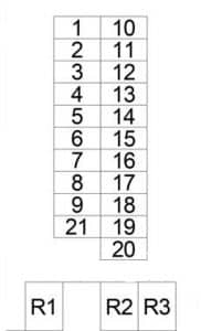
Audi V8 (1988 – 1994) – fuse box diagram

Audi V8 (1988 – 1994) – fuse box diagram

Year of production: 1988, 1989, 1990, 1991, 1992, 1993, 1994

Passenger Compartment Fuse Box

Audi V8 - fuse box diagram - passenger compartment
Audi V8 – fuse box diagram – passenger compartment
No.
A
Protected Component
1 15 Front Fog Light, Rear Fog Light
2 15 ’88-’90: Emergency Flasher
10 ’91-’94: Emergency Flasher
3 25 ’88-’90: Stop Lamp Switch, Horn
20 ’91-’94: Stop Lamp Switch, Horn, Auxiliary Radiator Fan (2nd/3rd Speed) (’93-’94)
4 15 Interior Lights, Cigarette Lighter, Luggage Compartment Light, Trip Computer, Climate Control System, Radio/Speakers, Auxiliary Radiator Fan (1st Speed), Vanity Mirror Light, Clock, Socket
5 10 Oxygen Sensor Heating Element
30 Cooling Fan (Full Speed)
6 5 Right Side Marker & Park Lights, Daytime Headlights (Canada), Right Taillights (’93-’94)
7 5 Left Side Marker & Park Lights, Left Taillights (’93-’94)
8 10 Right High Beam Headlight, High Beam indicator
9 10 Left High Beam Headlight
10 10 Right Low Beam Headlight
11 10 Left Low Beam Headlight
12 15 Headlight Washer, Auxiliary Washer, Rear Light Control Unit, Back-Up Lights, ABS Control Unit, Auto Shift Lock, Car Phone (’93-’94), Differential Lock, Cruise Control
13 15 Fuel Pump
14 5 License Plate Light, Center Console Light, Glove Box Light, Engine Compartment Light, Instrument Cluster (’93-’94)
15 25 ’88-’90: Wiper/Washers, Turn Signals, Heated Washer Jets, Air Conditioner
15 ’91-’94: Wiper/Washers, Turn Signals, Heated Washer Jets
16 30 ’88-’90: Rear Window Defogger, Heated Mirror
20 ’91-’94: Rear Window Defogger, Heated Mirror
17 30 ’88-’90: Air Conditioner, Heater Blower
20 ’91-’94: Air Conditioner, Heater Blower
18 25 ’88-’90: Power Seats witch Memory
5 ’91-’94: Power Seats Memory, Outside Mirror, Central Locking System (’93-’94)
19 10 Central Locking System, Heated Door Lock, Anti-Theft Alarm System
30 Central Locking System, Heated Door Lock
15 ’91-’94: Central Locking System, Heated Door Lock
20 25 ’88-’90: Heated Seats
30 ’88-’90: Cooling Fan (Low Speed), Cooling Fan Relay
30 ’91-’94: Heated Seats
21 20 ’88-’90: Power Windows
25 ’91-’94: Power Windows, Rear Cigarette Lighter
22  –
23 10 Injected Valves, Heated-Wire Air Flow Sensor
24 15 Active Carbon Canister Valve, Idle Stabilization
25 30 Power Seats witch Memory
26 5 Cruise Control
27 5 Motronic Engine Control System
28 5 ’88-’90: Instrument Cluster
15 ’91-’94: Instrument Cluster
29 10 Automatic Transmission
30 5 Instrument Cluster, Trip Computer & Function Control Switch, Auto-Check System
31  –
Relay
R1 Horn
R2 Foglights
R3 Automatic Transmission
R4  –
R5 Washer/Wiper Intermittent
R6  –
R7 Fuel Pump
R8  –
R9 Load Reduction
R10  –
R11  –
R13 Radiator Cooling Fan (3rd Stage)
Circuit Breaker
R12 Power Window, Power Seats

Passenger Compartment Relay Box No.1

Audi V8 - fuse box diagram - passenger compartment relay box no. 1
Audi V8 – fuse box diagram – passenger compartment relay box no. 1
No.
Relay
R1 Air Conditioner
R2 Catalytic Converter
R3 Radiator Coolant Fan (Low Speed)
R4 Front Light
R5 Power Window/Sun Roof
R6  –
R7  –
R8 Radiator Cooling Fan
R9 ABS Combination

Passenger Compartment Relay Box No.2

Audi V8 - fuse box diagram - passenger compartment relay box no. 2
Audi V8 – fuse box diagram – passenger compartment relay box no. 2
No.
Relay
R1  –
R2 Speaker
R3 Anti-Theft Alarm Light Warning
R4 Driver Heated Seat
R5 Passenger Heated Seat
R6 Shift Lock
R7 Back-Up Light
R8 Auxiliary Wash Pump
R9 Left Rear Heated Seat
R10 Right Rear Heated Seat

WARNING: Terminal and harness assignments for individual connectors will vary depending on vehicle equipment level, model, and market.

AMC Gremlin (1970 – 1978) – fuse box diagram

AMC Gremlin (1970 – 1978) – fuse box diagram

Year of production: 1970, 1971, 1972, 1973, 1974, 1975, 1976, 1977, 1978

Type 1

AMC Gremlin - fuse box diagram - type 1
AMC Gremlin – fuse box diagram – type 1
No.
A
Protected Component
1 9 Dome light, cargo, courtesy, clock, glove box, and trunk light
2 14 Tail, park and instrument lights, light switch, windshield wiper, heater, cigar lighter, clock, license light, transmission, air conditioning thermostat, radio, tachometer, ash tray light, seat belt module and key buzzer
3 20 Stop light and hazard warning flasher
4 20 Turn signal, back-up lights and accessories
5 Panel lights
6 4 Gauges
7 20 Fan

Circuit Breaker:

  • Headlights — 20 amp. circuit breaker in headlight switch.
  • Windshield Wiper – 6 amp. circuit breaker in wiper switch.
  • Power Windows & Tailgate Switches — 20 amp. circuit breakers located in instrument panel.

Type 2

AMC Gremlin - fuse box diagram - type 2
AMC Gremlin – fuse box diagram – type 2
No.
A
Protected Component
1 10 Parking lights, key/headlights warning buzzer
2 15 Stop light and hazard warning
3  –
4 3 Cluster illumination
5  –
6  –
7 25 Heater/blower motor, A/C clutch
8 15 Radio, cigar lighter
9 15 Turn signals, backup lights, windshield washers
10 5 Gauges, seat belt warning
11 30 Power door lock, power windows circuit breaker
12 25 Heated rear window
Circuit Breaker:

  • Headlights — 20 amp. circuit breaker in headlight switch
  • Windshield Wiper — 6 amp. circuit breaker in wiper switch.
  • Power Windows & Tailgate Switches — 20 amp. circuit breakers located in instrument panel

WARNING: Terminal and harness assignments for individual connectors will vary depending on vehicle equipment level, model, and market.
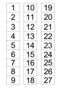
AMC Concord (1979 – 1983) – fuse box diagram

AMC Concord (1979 – 1983) – fuse box diagram

Year of production: 1979, 1980, 1981, 1982, 1983

Fuse box diagram

AMC Concord - fuse box diagram
AMC Concord – fuse box diagram
No.
A
Protected Component
1 10 Parking lights, key/headlights warning buzzer
2 15 Stop light and hazard warning
3  –
4 3 Cluster illumination
5  –
6  –
7 25 Heater/blower motor, A/C clutch
8 15 Radio, cigar lighter
9 15 Turn signals, backup lights, windshield washers
10 5 Gauges, seat belt warning
11 30 Power door lock, power windows circuit breaker
12 25 Heated rear window
Circuit Breaker:

  • Headlights — 20 amp. circuit breaker in headlight switch
  • Windshield Wiper — 6 amp. circuit breaker in wiper switch.
  • Power Windows & Tailgate Switches — 20 amp. circuit breakers located in instrument panel.

WARNING: Terminal and harness assignments for individual connectors will vary depending on vehicle equipment level, model, and market.
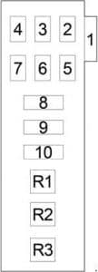
AMC Spirit (1979 – 1983) – fuse box diagram

AMC Spirit (1979 – 1983) – fuse box diagram

Year of production: 1979, 1980, 1981, 1982, 1983

Fuse box diagram

AMC Spirit - fuse box diagram
AMC Spirit – fuse box diagram
No.
A
Protected Component
1 10 Parking lights, key/headlights warning buzzer
2 15 Stop light and hazard warning
3  –
4 3 Cluster illumination
5  –
6  –
7 25 Heater/blower motor, A/C clutch
8 15 Radio, cigar lighter
9 15 Turn signals, backup lights, windshield washers
10 5 Gauges, seat belt warning
11 30 Power door lock, power windows circuit breaker
12 25 Heated rear window
Circuit Breaker:

  • Headlights — 20 amp. circuit breaker in headlight switch
  • Windshield Wiper — 6 amp. circuit breaker in wiper switch.
  • Power Windows & Tailgate Switches — 20 amp. circuit breakers located in instrument panel.

WARNING: Terminal and harness assignments for individual connectors will vary depending on vehicle equipment level, model, and market.
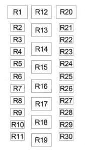
AMC Hornet (1975) – fuse box diagram

AMC Hornet (1975) – fuse box diagram

Year of production: 1975

Fuse box diagram

AMC Hornet - fuse box diagram
AMC Hornet – fuse box diagram
No. A
Protected Component
1 9 Dome light, cargo, courtesy, clock, glove box, and trunk light
2 14 Tail, park and instrument lights, light switch, windshield wiper, heater, cigar lighter, clock, license light, transmission, air conditioning thermostat, radio, tachometer, ash tray light, seat belt module and key buzzer
3 20 Stop light and hazard warning flasher
4 20 Turn signal, back-up lights and accessories
5 Panel lights
6 4 Gauges
7 20 Fan
Circuit Breaker:

  • Headlights — 20 amp. circuit breaker in headlight switch.
  • Windshield Wiper – 6 amp. circuit breaker in wiper switch.
  • Power Windows & Tailgate Switches — 20 amp. circuit breakers located in instrument panel.

WARNING: Terminal and harness assignments for individual connectors will vary depending on vehicle equipment level, model, and market.
AMC Matador (1974 – 1978) – fuse box diagram

AMC Matador (1974 – 1978) – fuse box diagram

Year of production: 1974, 1975, 1976, 1977, 1978

Fuse box diagram

AMC Matador - fuse box diagram
AMC Matador – fuse box diagram
No.
A
Protected Component
1 20 Turn signal, back-up lights, radio, windshield washer
2 20 Blower motor, air conditioner clutch
3 4 Interlock module circuit, headlight warning buzzer, oil light indicator, park brake, brake failure circuit
4 4 Panel illumination lights
5 14 Interlock module circuit, windshield wiper, park, tail, license and side marker lights
6 20 Stop light and hazard warning flasher
7 9 Dome, courtesy, glove box, trunk and cargo lights, clock
Circuit Breaker:

  • Headlights — 20 amp. circuit breaker in headlight switch.
  • Windshield Wiper – 6 amp. circuit breaker in wiper switch.
  • Power Windows & Tailgate Switches — 20 amp. circuit breakers located in instrument panel.

WARNING: Terminal and harness assignments for individual connectors will vary depending on vehicle equipment level, model, and market.