VW Polo GTI mk5 – fuse box diagram
Year of production
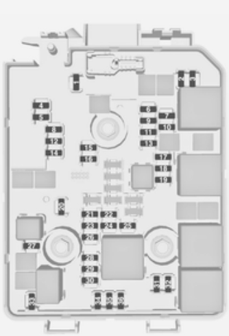
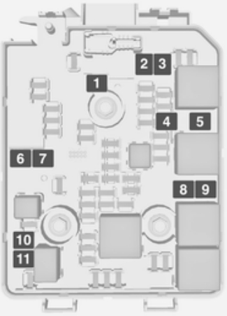
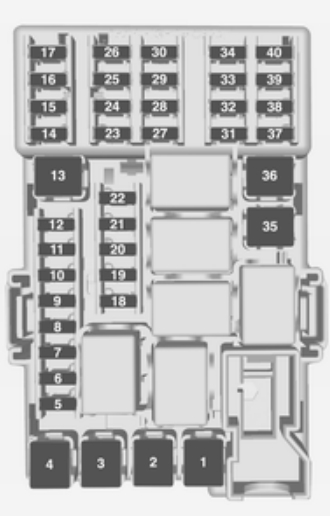
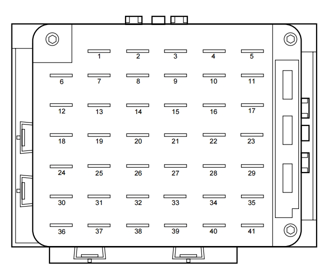
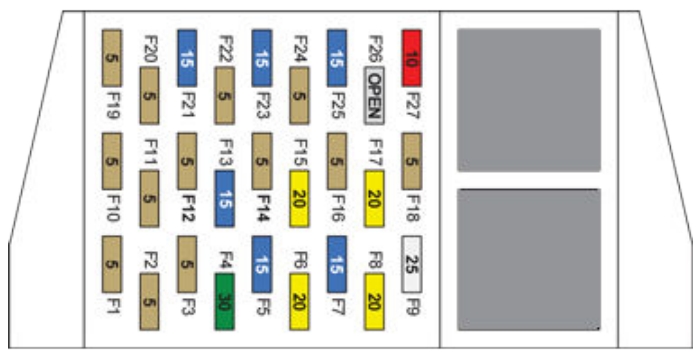
Fuse box
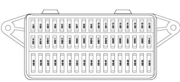
| Fuse | Description | Ampere rating [A] |
| SB1 | Lambda probe heating, ACF, camshaft, variable timing adjuster | 10 |
| SB2 | Number plate lights | 5 |
| SB3 | Injectors | 10 |
| SB4 | Side bulb left | 5 |
| SB5 | Side light bulb | 5 |
| SB6 | Rear wiper | 15 |
| SB7 | Turn signals | 7,5 |
| SB8 | ABS with EDL/ESP | 5 |
| SB9 | Headlight range control | 5 |
| SB10 | Interior lighting, glove box, mirror, door entry, luggage, compartment light | 7,5 |
| SB11 | Self-diagnosis connection voltage supply, dash panel insert, Climatronic | 5 |
| SB12 | Right headlight main beam main beam warning lamp | 10 |
| SB13 | Left main beam headlight | 10 |
| SB14 | Hazard warning lights system and-theft alarm system | 10 |
| SB15 | Brake lights | 10 |
| SB16 | Ignition/starter switch S-connect | 5 |
| SB17 | Not used | — |
| SB18 | Mirror heating | 5 |
| SB19 | Horn | 5 |
| SB20 | Telephone/preparation for telephone | 10 |
| SB21 | Automatic gearbox control unit | 5 |
| SB22 | Anti-theft alarm system horn | 15 |
| SB23 | EGR, air mass meter, addit, heater relay, glow plug relay | 5 |
| SB24 | Clutch pedal switch (diesel), brake light suppression switch (EPC) | 5 |
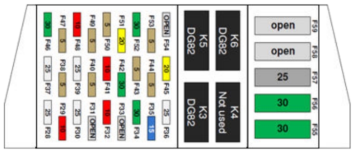
| SB25 | Selector lever switch (AG4) | 5 |
| SB26 | Air conditioner, central locking, electric windows, electric mirror, navigation | 7,5 |
| SB27 | Dash panel insert | 5 |
| SB28 | Speedometer sender immobilizer | 5 |
| SB29 | Reversing lights, washer jet heating, headlight range control motor | 7,5 |
| SB30 | Exhaust gas recirculation valve, activated charcoal filter solenoid, heater pipe | 5 |
| SB31 | Fuel shut-off control unit, engine control unit | 5 |
| SB32 | Fusel shut-off control unit (diesel) | 5 |
| SB33 | Automatic gearbox selector level lock | 10 |
| SB34 | Ignition transformer | 10 |
| SB35 | Glass sunroof, fabric sunroof | 25 |
| SB36 | Engine control unit | 15 |
| SB37 | Engine control unit | 15 |
| SB38 | Driver’s door power window | 25 |
| SB39 | Front passenger’s power windows | 25 |
| SB40 | Fuel pump | 15 |
| SB41 | Central locking, anti-theft alarm system | 15 |
| SB42 | Radio, navigation | 15 |
| SB43 | Fog light, rear fog light | 15 |
| SB44 | Dipped beam, left headlight | 15 |
| SB45 | Dipped beam right headlight | 15 |
| SB46 | Cigarette lighter | 15 |
| SB47 | Headlight washer system | 20 |
| SB48 | Heated rear window | 20 |
| SB49 | Fresh air blower | 25 |
| SB50 | Windscreen wiper system, windscreen washer pump | 15 |
| SB51 | Seat heating | 15 |
WARNING: Terminal and harness assignments for individual connectors will vary depending on vehicle equipment level, model, and market.