Fiat 500 (2012 – 2014) – fuse box diagram (USA version)

Fiat 500 (2012 – 2014) – fuse box diagram (USA version)

Years: 2012, 2013, 2014

Interior fuses

The interior fuse panel is part of the Body Control Module (BCM) and is located on the drivers’s side under the instrument panel.

Cavity Vegicle fuse number Mini fuse (ampere fuse) Colour Description
1 F12 7,5 Brown Right Low Beam
2 F32 5 Tan Front and Rear Ceiling Lights Trunk and Door Courtesy Lights
3 F53 5 Tan Instrument Panel Node
4 F38 20 Yellow Central Door Locking
5 F36 10 Red Diagnostic Socket, Car Radio, Climate Control System
6 F43 20 Yellow Bi-Directional Washer
7 F48 20 Yellow Passenger Power Window
8 F13 7,5 Brown Left Low Beam, Headlamp Leveling
9 F50 7,5 Brown Airbag
10 F51 5 Tan Car Radio Switch, Climate Control System, Stop Light, Clutch
11 F37 5 Tan Stop Light Switch, Instrument Panel Node
12 F49 5 Tan Exterior Mirror, GPS, Electric Mirror, Parking Sensor
13 F47 20 Yellow Driver Power Window


Underhood fuses

The front distribution units is located on the right side of engine compartment, next to the battery.

Cavity Maxi fuse Mini fuse Description
F01 60A (Blue) Body Controller
F02 20A (Yellow) Audio Amplifier
F03 20A (Yellow) Ignition Switch
F04 40A (Orange) Anti-Lock Brake Pump
F05 70A (Tan) Electric Power Steering
F06 20 (Yellow) Radiator Fan – Single Speed
F07 40A (Orange) Radiator Fan – High Speed
F08 30A (Green) Blower Motor
F09 10A (Red) Powertrain
F10 10A (Red) Horn
F11 15A (Blue) Powertrain
F11 10A (Red) Powertrain (Multiair – If Equipped)
F14 5 (Tan) High beam (Shutter)
F15 15A (Blue) Cigar Lighter
F16 7,5 (Brown) Transmission
F17 25A (White) Powertrain (Multiair – If Equipped)
F17 15A (Blue) Powertrain
F18 15A (Blue) Powertrain
F18 5 (Tan) Powertrain (Multiair – If Equipped)
F19 7,5 (Brown) Air Conditioning
F20 15A (Blue) Heated Seats – If Equipped
F21 15A (Blue) Fuel Pump
F23 20A (Yellow) Anti-Lock Brake Valves
F24 7,5A (Brown) Stability Control System
F30 15A (Blue) Fog Lamps
F82 30A (Green) Sunroof/ Convertible Top
F84 10A (Red) Transmission
F85 15A (Blue) Rear Defroster, Heated Mirrors
F87 5A (Tan) Lights
F90 5A (Tan) Heated Mirrors

The ID number of the electrical component corresponding to each fuse can be found on the back of the cover.


WARNING: Terminal and harness assignments for individual connectors will vary depending on vehicle equipment level, model, and market.

Acura ILX Hybrid (from 2013) – fuse box diagram

Acura ILX Hybrid (from 2013) – fuse box diagram

Year of production: 2013, 2014, 2015, 2016


Fuse box in engine compartment

Fuse Circuit protected Ampere rating [A]
1 EPS 70
Booster Motor 40
ABS/VSA Motor 30
ABS/VSA FSR 30
WIPER 30
MAIN Fuse 100
2 IG MAin 50
Fuse Box Main 60
Fuse Box Main 2 60
Headlight Main 30
ST/MG SW*1 30
 Rear Defogger 30
Blower 40
Sub Fan Motor 20
3
4 IG Coil 2 15
5 Starter DIAG, ST MG 7,5
6 IG Coil 1 15
7
8
9
10
11 Oil Level 7,5
12 Fog lights 20
13 IMA1 7,5
14 Hazard 10
15 FI Sub 15
16 IG Coil 20
17 Stop 15
18 Horn 10
19 IMA2 10
20 Right Headlight Low Beam*1 10
Right Headlight Low Beam (HID)*2 15
21 IGP 15
22 DBW 15
23 Left Headlight Low Beam*1 10
Left Headlight Low Beam(HID)*2 15
24 Booster SOL 15
25 MG Clutch 7,5
26 WASHER 7,5
27 SMALL 20
28 Interior Lights 7,5
29 Backup 10

*1:Models with halogen bulb low beam headlights

*2:Models with discharge headlights

Relay

Acura ILX - fuse box - engine compartment (front side)
Acura ILX – fuse box – engine compartment (front side)
Position Description
M1 Blower Motor Relay
M2 Starter Cut Relay 1
M3 A/C Condenser Fan Relay
M4 Ignition Coil Relay
M5 Starter Cut Relay 2
M6 PGM-FI Subrelay
M7 Rear Window Defogger Relay
256 ELD
258 Fan Control Relay
259 Fog Light Relay
265 Horn Relay
273 Radiator Fan Relay
274 NC Compressor Clutch Relay
287 Windshield Wiper Motor Relay
288 Relay Circuit Board
320 Diode D
321 Diode C

Connector

Position Connector name Connector type
T1 T1 Component Connector
T101 T101 Component Connector

Interior fuse box

Fuse Circuit protected Ampere rating [A]
1
2 ACG 15
3 SRS 10
4 Fuel pump 15
5 Meter 7,5
6 Power Window 7,5
7 VB SOL* 7,5
8 Door Lock Motor 2 (Unlock) 15
9 Door Lock Motor 1 (Unlock) 15
10
11 Moonroof 20
12 Driver’s Power Seat Sliding* 20
13 Driver’s Power Seat Reclining* 20
14 Seat Heaters* 15
15 Driver’s Door Lock Motor (Unlock)
16
17
18
19 ACC 7,5
20 ACC Key Lock 7,5
21 Daytime Running Lights 7,5
22 HAC 7,5
23 HYBRID A/C 7,5
24 ABS/VSA 7,5
25 ACC 7,5
26
27 Accessory Power Socket 20
28
29 ODS 7,5
30 Driver’s Door Lock Motor (Lock) 10
31 SMART 10
32 Door Lock Motor 2 (Lock) 15
33 Door Lock Motor 1 (Lock) 15
34 Small Lights 7,5
35 Illumination 7,5
36
37 Premium Audio* 20
38 Left Headlight High Beam 10
39 Right Headlight High Beam 10
40 TPMS* 7,5
41 Door Lock 20
42 Driver’s Power Window 20
43 Rear Passenger’s Side Power Window 20
44 Front Passenger’s Side Power Window 20
45 Rear Driver’s Side Power Window 20
46

* Not available on all models


WARNING: Terminal and harness assignments for individual connectors will vary depending on vehicle equipment level, model, and market.

Acura CL (2003) – fuse box diagram

Acura CL (2003) – fuse box diagram

Year of production: 2003

Fuse box in engine compartment (under hood)

Acura CL (2001) - fuse box - engine copmartment
Acura CL (2003) – fuse box – engine copmartment
Fuse Ampere rating [A] Circuits Protected
1*1  20 Condenser Fan
1*2 30 Condenser Fan
2 7,5 MG Clutch
3 60 IG1 Main
4 40 Rear Window Defogger
5 40 Heater Motor
6*1 20 TCS
6*2 40 VSA
6*3 Not used
7 40 Power Seat
8 40 Power Window Motor
9 40 Back Up, ACC
10 15 Spare Fuse
11 10 Spare Fuse
12 7,5 Spare Fuse
13*1,*3 20 Cooling Fan
13*2 30 Cooling Fan
14 120 Battery
15 30 Spare Fuse
16 20 Spare Fuse
17 15 Hazard
18 30 ABS Motor
19 15 ACG S
20 20 Stop
21 20 ABS F/S Relay
22 20 Right Headlight
23 Not used
24 20 Left Headlight

*1 – Premium model

*2 – Type-S with A/T

*3 – Type-S with M/T

Interior fuse boxe – driver’s side

Acura CL (2001) - fuse box - interior driver's side
Acura CL (2003) – fuse box – interior driver’s side
Fuse Ampere rating [A] Circuits Protected
1 15 Fuel Pump
2 10 Main SRS
3 7,5 Heater Control, A/C Clutch Relay, Cooling Fan Relay
4 7,5 Mirror, Heated Seat, Heated Mirror
5 7,5 Daytime Running Lights*
6 15 ECU (PCM), Cruise Control, VSA
7 7,5 Side SRS
8 7,5 ACC Relay, Navigation
9 7,5 Instrument Panel, Back-up Lights, Memory Seat
10 7,5 Turn Signals
11 15 IG Coil
12 30 Wiper, Washer
13 7,5 Starter Signal

*-On Canadian models

Interior fuse boxe – passenger’s side

Acura CL (2001) - fuse box - interior passenger's side
Acura CL (2003) – fuse box – interior passenger’s side
Fuse Ampere rating [A] Circuits protected
1 30 Left Power Window
2 20 Driver’s Power Seat Reclining, Memory Seat
3 20 Heated Seat
4 20 Driver’s Power Seat Sliding, Memory Seat
5 20 Passenger’s Power Seat Sliding
6 20 Passenger’s Power Seat Reclining
7 30 Moonroof Motor
8 20 Right Power Window
9 20 Radio, Power Outlet
10 10 Navigation System, Daytime Running Lights*1, OnStar*2
11 7,5 Interior Light, Seat Memory, HomeLink
12 20 Power Door Locks
13 15 Clock, Back Up, Small Light
14 7,5 ABS Motor Check
15 Not used
16 Not used

*1 – On Canadian models

*2 – On cars with navigation system

VSA fuse box (on type S with A/T)

Acura CL (2001) - fuse box - vsa (type S)
Acura CL (2001) – fuse box – vsa (type S)
Fuse Ampere rating [A] Circuits protected
1 20 VSA F/S Relay
2 20 VSA Throttle Motor
3 Not Used


WARNING: Terminal and harness assignments for individual connectors will vary depending on vehicle equipment level, model, and market.

Lincoln Aviator (UN152; 2002 – 2003) – fuse and relay box diagram

Lincoln Aviator (UN152; 2002 – 2003) – fuse and relay box diagram

Year of production: 2002, 2003

This article focuses on the first-generation Lincoln Aviator (UN152), manufactured between 2002 and 2005. It includes fuse box diagrams for the 2002 and 2003 models, provides information on the location of the fuse panels within the vehicle, and explains the function and layout of each fuse and relay.


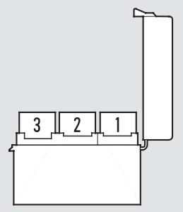
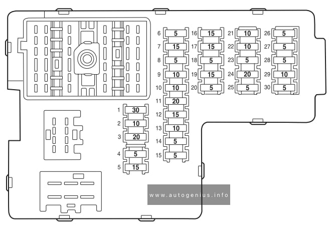
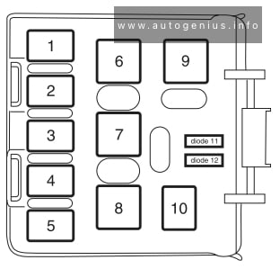
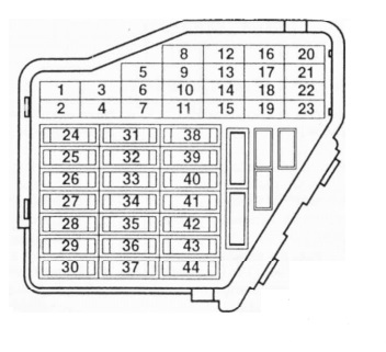
Passenger compartment fuse panel

Fuse box location

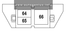
The fuse panel is located under the instrument panel to the left of the steering column. The relays are located on the reverse side of the passenger compartment fuse panel. To access the relays, you must remove the fuse panel.


Fuse box diagram

Lincoln Aviator (UN152; 2002 - 2003) - fuse box diagram - passenger compartment box
Lincoln Aviator (UN152; 2002 – 2003) – fuse box diagram – passenger compartment box


Assignment of the fuses in the Instrument panel (2002 – 2003)

Amp Rating Description
1 30A Moonroof, Driver seat switch
2 10A VAPS module, Memory seat module, Body security module, TPMS
3 20A Radio, Navigation
4 5A Front wiper module
5 15A Flasher relay (turn/hazards)
6 5A Power antenna, Radio, Moonroof motor, Driver window motor, Navigation
7 15A Heated mirrors, DEATC module
8 5A Daytime Running Lamps (DRL) module
9 10A Back-up lamps (DTRS)
10 10A Heated backlight relay coil, Climate seat modules, Auxiliary A/C temperature blend/mode actuator, A/C clutch relay contact
11 20A Not used (spare)
12 15A Restraints module
13 10A Brake shift interlock
14 5A Cornering lamps
15 5A Instrument cluster, Rear wiper module, TPMS
16 15A Cigar lighter, OBD II, Liftgate release relay coil and contacts
17 15A Delayed accessory relay coil, Battery saver relay coil and contacts
18 5A Not used (spare)
19 15A Washer pump
20 5A Shifter, Clock, Power mirror switch, DVD
21 10A Brake pressure switch (ABS), IVD switch, Flasher relay
22 10A ABS module
23 5A Sunload/Autolamp sensor (SecuriLock transceiver LED)
24 20A Subwoofer, Navigation
25 5A Puddle lamp relay coil, Trailer tow batten charge relay coil
26 5A SecuriLock transceiver
27 5A Rear park assist, VAPS module
28 5A Radio, Navigation
29 10A DTRS, Feed to Fuse 28
30 5A Instrument cluster, Compass module, Auxiliary A/C relay coil


Relay in passeneger compartment (located on the reverse side of the fuse box)

Relay box diagram

Lincoln Aviator (UN152; 2002 - 2003) - fuse box diagram - passenger compartment box (relay)
Lincoln Aviator (UN152; 2002 – 2003) – fuse box diagram – passenger compartment box (relay)


Assignment of the relays in the Instrument panel (2002 – 2003)

Relay № Description
1 Flasher relay
2 Heated backlight relay
3 Delayed accessory relay
4 Open
5 Batteiy saver relay
6 Open
7 Open


Engine compartment (power distribution box)

Fuse box diagram

Lincoln Aviator (UN152; 2002 - 2003) - fuse box diagram - engine compartment box
Lincoln Aviator (UN152; 2002 – 2003) – fuse box diagram – engine compartment box


Assignment of the fuses in the engine compartment (2002 – 2003)

Amp Rating Description
1 60A PJB
2 30A Door locks (BSM)
3 Not used
4 40A Heated backlight/mirrors
5 40A Anti-lock Brake System (ABS) module (pump)
6 60A Delayed accessory
7 20A DRL module
8 20A Electric cooling fan
9 20A Headlamp switch
10 30A ABS module (valves)
11 40A PTEC relay contacts
12 50A Ignition/Starter relay
13 40A Trailer tow relays
14 15 A Brake lamp feed
15 10A Keep alive power (PTEC/cluster/DEATC)
16 20A Power point #3
17 20A Rear wiper module
18 20A 4×4 module
19 30A Driver window motor
20 30A Electric trailer brakes
21 30A Memory seat module
22 20A Main exterior lamps (low beam headlamps, high beam headlamps, fog lamps)
23 30A Ignition switch
24 20A Horn relay
25 20A Power point #1
26 20A Fuel pump relay contacts
27 20A Trailer tow lamps
28 20A Power point #2
29 60A PJB
30 30A Front wiper module
31 30A Climate-controlled seats modules
32 30A Passenger seat switch
33 30A Auxiliary blower motor
34 20A Right HID relay
35 20A Left HID relay
36 40A Blower motor
37 15 A A/C clutch relay, TXV, Transmission, Speed control
38 15 A HEGO, VMV, Canister vent, IMCC-LSRC, Heated PCV, EGR module
39 15 A Injectors
40 15 A PTEC, Mass Air Flow (MAF) sensor, Fuel pump relay
41 25A Coil on plug, PTEC relay
42 10A Right low beam (halogen)
43 10A Left low beam (halogen)
44 15 A Fog lamp relay
45 2A Brake Pressure Switch
46 20A High beam
47 Horn relay
48 Fuel pump relay
49 High beam relay
50 Fog lamp relay
51 Not used
52 A/C clutch relay
53 Trailer tow right turn relay
54 Trailer tow left turn relay
55 Blower motor relay
56 Starter motor relay
57 PTEC relay
58 Ignition relay
59 Driver brake applied relay
60 PCM diode
61 A/C clutch diode
62 30A Power windows (Circuit breaker)

Auxiliary relay box

Relay box diagram

Lincoln Aviator (UN152; 2002 - 2003) - fuse box diagram - engine compartment box - auxiliary relay box
Lincoln Aviator (UN152; 2002 – 2003) – fuse box diagram – engine compartment box – auxiliary relay box


Assignment of the fuses in the auxiliary relay box (2002 – 2003)

Relay № Description
64 Right HID relay
65 Left HID relay
66 EDF relay


Rear relay box

Relay box location

The relay box is located on the rear passenger side quarter trim panel.


Relay box diagram

Lincoln Aviator (UN152; 2002 - 2003) - fuse box diagram - rear compartment box
Lincoln Aviator (UN152; 2002 – 2003) – fuse box diagram – rear compartment box


Assignment of the fuses in the rear relay box (2002 – 2003)

Relay № Description
1 Liftgate release solenoid
2 Open
3 Open
4 Trailer tow back-up lamps
5 Open
6 Open
7 Trailer tow battery charge
8 Trailer tow park lamps
9 Open
10 2003: Puddle lamps
2004-2005: Open
Diode 11 Open
Diode 12 Open


WARNING: Terminal and harness assignments for individual connectors will vary depending on vehicle equipment level, model, and market.

Acura CL (2001 – 2002) – fuse box diagram

Acura CL (2001 – 2002) – fuse box diagram

Year of production: 2001, 2002

Fuse box in engine compartment (under hood)

Acura CL (2001) - fuse box - engine copmartment
Acura CL – fuse box – engine copmartment
Fuse Ampere rating [A] Circuits Protected
1*1  20 Condenser Fan
1*2 30 Condenser Fan
2 7,5  MG Clutch
3 60 IG1 Main
4 40  Rear Window Defogger
5 40 Heater Motor
6*1 20 TCS
6*2 40 VSA
7 40 Power Seat
8 40 Power Window Motor
9 40 Back Up, ACC
10 15 Spare Fuse
11 10 Spare Fuse
12 7,5 Spare Fuse
13*1 20 Cooling Fan
13*1 30 Cooling Fan
14 120 Battery
15 30 Spare Fuse
16 20 Spare Fuse
17 15 Hazard
18 30 ABS Motor
19 15 ACG S
20 20 Stop
21 20 ABS F/S Relay
22 20 Right Headlight
23 Not used
24 20 Left Headlight

*1 – Premium model

*2 – Type S

Interior fuse boxe – driver’s side

Acura CL (2001) - fuse box - interior driver's side
Acura CL – fuse box – interior driver’s side
Fuse Ampere rating [A] Circuits Protected
1 15 Fuel Pump
2 10 Main SRS
3 7,5 Heater Control, A/C Clutch Relay, Cooling Fan Relay
4 7,5 Mirror, Heated Seat, Heated Mirror
5 7,5 Daytime Running Lights*
6 15 ECU (PCM), Cruise Control, VSA
7 7,5 Side SRS
8 7,5 ACC Relay, Navigation
9 7,5 Instrument Panel, Back-up Lights, Memory Seat
10 7,5 Turn Signals
11 15 IG Coil
12 30 Wiper, Washer
13 7,5 Starter Signal

*-On Canadian models

Interior fuse boxe – passenger’s side

Acura CL (2001) - fuse box - interior passenger's side
Acura CL  – fuse box – interior passenger’s side
Fuse Ampere rating [A] Circuits protected
1 30 Moonroof Motor
2 20 Driver’s Power Seat Reclining, Memory Seat
3 20 Heated Seat
4 20 Driver’s Power Seat Sliding, Memory Seat
5 20 Passenger’s Power Seat Sliding
6 20 Passenger’s Power Seat Reclining
7 Not used
8 20 Right Power Window
9 20 Radio, Power Outlet
10 10 Navigation System, Daytime Running Lights*
11 7,5 Interior Light, Seat Memory, HomeLink
12 20 Power Door Locks
13 15 Clock, Back Up, Small Light
14 7,5 ABS Motor Check
15 20 Driver’s Power Window
16 Not used

*-On Canadian models

VSA fuse box (on type S)

Acura CL (2001) - fuse box - vsa (type S)
Acura CL  – fuse box – vsa (type S)
Fuse Ampere rating [A] Circuits protected
1 20 VSA F/S Relay
2 20 VSA Throttle Motor
3 Not Used


WARNING: Terminal and harness assignments for individual connectors will vary depending on vehicle equipment level, model, and market.

Volkswagen Golf mk6 GTI – fuse box

VW Golf mk6 GTI – fuse box


Fuse box in passeneger compartment

Volkswagen Golf mk6 GTI - fuse box - passeneger compartment
Volkswagen Golf mk6 GTI – fuse box – passeneger compartment
Electrical consumers Fuse number (amp rating in brackets)
Electrical socket for trailer 2 (10); 43 (15); 44 (20); 45 (15)
ABS, ESP 2 (10); 4 (5)
Anti-tow alarm 17 (5)
Airbag 3 (5)
Brake light switch 2 (10)
Front electric windows 23 (20)
Rear electric windows 26 (30)
Blower 22 (40); 40 (40)
Rear window heating 25 (25)
Rear wiper 41 (20)
Interior monitoring 17 (10)
Air conditioner operating unit 14 (10)
Combi – instrument 2 (10)
Fuel pump 27 (15)
Lumbar support 34 (15)
Headlight range control 1 (10)
Rain sensor 13 (10)
Selector mechanism for the automatic gearbox 14 (10)
Headlight washer system 36 (20)
Sliding/tilting roof 33 (20)
Seat heating 37 (30)
Socket in front 12V 42 (30)
Socket in luggage compertment 12V 42 (20)
Central electronic control unit 24 (20)
Central locking for front doors 12 (10)
Central locking for rear doors 15 (20)
Cigarette lighter 42 (20)

Fuse box in engine compartment

Volkswagen Golf mk6 GTI - fuse box - engine compartment
Volkswagen Golf mk6 GTI – fuse box – engine compartment

Electrical consumers Fuse location (amp rating in brackets)
Horn F17 (15)
Radiator fan F24 (10)
Fog light F26 (30); F16 (30)
Rear fog light F26 (30); F16 (30)
Radio F8(25)/(15)
Windscreen washer jets, heated F26 (30)
Left headlight F26 (30)
Right headlight F16 (30)
Sound system F18 (30)
Left side light F26 (30)
ABS, ESP F4 (20); F25 (40)
Left turn signal F26 (30)
Right turn signal F16 (30)
Brake light, right F16 (30)
Brake light, left F26 (30)
Windscreen wiper F19 (30)


WARNING: Terminal and harness assignments for individual connectors will vary depending on vehicle equipment level, model, and market.

Volkswagen Jetta mk4 (1997 – 2003) – fuse box

VW Jetta mk4 (1997 – 2003) – fuse box

Year of production: 1997, 1998, 1999, 2000, 2001, 2002, 2003

Passenger compartment


Volkswagen Golf mk4 - fuse box - passeneger compartment
Volkswagen Jetta mk4 – fuse box – passeneger compartment
Fuse Ampere rating [A] Description
1 10 Washer nozzle heaters, glove compartment light, memory seat control module
2 10 Turn signal lights
3 5 Fog light relay, instrument panel light dimmer switch
4 5 License plate light
5 7,5 Comfort system, cruise control, Climatronic, A/C, heated seat control modules, automatic day/night interior mirror, control module for multi-function steering wheel, control unit in steering wheel
6 5 Central locking system
7 10 Back-up lights, speedometer vehicle speed sensor (VSS)
8 Open
9 5 Anti-lock brake system (ABS)
10 10 Engine control module (ECM): gasoline engine
5 Engine control module (ECM): diesel engine, Model Year 2000
11 5 Instrument cluster, shift lock solenoid
12 7,5 Data Link Connector (DLC) power supply
13 10 Brake tail lights
14 10 Interior lights, central locking system
15 5 Instrument cluster, transmission control module (TCM)
16 10 A/C clutch, after-run coolant pump
17 Open
18 10 Headlight high beam, right
19 10 Headlight high beam, left
20 15 Headlight low beam, right
21 15 Headlight low beam, left
22 5 Parking lights right, side marker right
23 5 Parking lights left, side marker left
24 20 Windshield and rear window washer pump, windshield wiper motor
25 25 Fresh air blower, Climatronic, A/C
26 25 Rear window defogger
27 15 Motor for rear windshield wiper
28 15 Fuel pump (FP)
29 15 Engine control module (ECM): gasoline engine
10 Engine control module (ECM): diesel engine
30 20 Power sunroof control module
31 20 Transmission control module (TCM)
32 10 Injectors: gasoline engine
15 Injectors: diesel engine
33 20 Headlight washer system
34 10 Engine control elements
35 30 12 V power outlet (in luggage compartment)
36 15 Fog lights
37 10 Terminal (86S) on radio, Instrument cluster
38 15 Central locking system (with power windows), luggage compartment light, remote/fuel tank door, motor to unlock rear lid
39 15 Emergency flashers
40 20 Dual tone horn
41 15 Cigarette lighter
42 25 Radio
43 10 Engine control elements
44 15 Heated seats

Fuse arangements in fuse bracket/battery:

Volkswagen Golf mk4 -fuse box - battery
Volkswagen Jetta mk4 -fuse box – battery
Fuse Ampere rating [A] Description
S162 50 Glow plugs (coolant)
S163 50 Fuel pump (FP) relay/glow plug relay
S164 40 Coolant fan control (FC) control module/coolant fan
S177 90 / 110 Generator (GEN)
120 / 150
S178 30 ABS (hydraulic pump)
S179 30 ABS
S180 30 Coolant fan


WARNING: Terminal and harness assignments for individual connectors will vary depending on vehicle equipment level, model, and market.

Volkswagen Golf mk4 – fuse box

VW Golf mk4 (1997 – 2003) – fuse box

Year of production:

Passenger compartment

Volkswagen Golf mk4 - fuse box - passeneger compartment
Volkswagen Golf mk4 – fuse box – passeneger compartment
Fuse Ampere rating [A] Description
1 10 Washer nozzle heaters, glove compartment light, memory seat control module
2 10 Turn signal lights
3 5 Fog light relay, instrument panel light dimmer switch
4 5 License plate light
5 7,5 Comfort system, cruise control, Climatronic, A/C, heated seat control modules, automatic day/night interior mirror, control module for multi-function steering wheel, control unit in steering wheel
6 5 Central locking system
7 10 Back-up lights, speedometer vehicle speed sensor (VSS)
8 Open
9 5 Anti-lock brake system (ABS)
10 10 Engine control module (ECM): gasoline engine
5 Engine control module (ECM): diesel engine, Model Year 2000
11 5 Instrument cluster, shift lock solenoid
12 7,5 Data Link Connector (DLC) power supply
13 10 Brake tail lights
14 10 Interior lights, central locking system
15 5 Instrument cluster, transmission control module (TCM)
16 10 A/C clutch, after-run coolant pump
17 Open
18 10 Headlight high beam, right
19 10 Headlight high beam, left
20 15 Headlight low beam, right
21 15 Headlight low beam, left
22 5 Parking lights right, side marker right
23 5 Parking lights left, side marker left
24 20 Windshield and rear window washer pump, windshield wiper motor
25 25 Fresh air blower, Climatronic, A/C
26 25 Rear window defogger
27 15 Motor for rear windshield wiper
28 15 Fuel pump (FP)
29 15 Engine control module (ECM): gasoline engine
10 Engine control module (ECM): diesel engine
30 20 Power sunroof control module
31 20 Transmission control module (TCM)
32 10 Injectors: gasoline engine
15 Injectors: diesel engine
33 20 Headlight washer system
34 10 Engine control elements
35 30 12 V power outlet (in luggage compartment)
36 15 Fog lights
37 10 Terminal (86S) on radio, Instrument cluster
38 15 Central locking system (with power windows), luggage compartment light, remote/fuel tank door, motor to unlock rear lid
39 15 Emergency flashers
40 20 Dual tone horn
41 15 Cigarette lighter
42 25 Radio
43 10 Engine control elements
44 15 Heated seats


Fuse arangements in fuse bracket/battery:

Volkswagen Golf mk4 -fuse box - battery
Volkswagen Golf mk4 -fuse box – battery
Fuse Ampere rating [A] Description
S162 50 Glow plugs (coolant)
S163 50 Fuel pump (FP) relay/glow plug relay
S164 40 Coolant fan control (FC) control module/coolant fan
S177 90 / 110 Generator (GEN)
120 / 150
S178 30 ABS (hydraulic pump)
S179 30 ABS
S180 30 Coolant fan


WARNING: Terminal and harness assignments for individual connectors will vary depending on vehicle equipment level, model, and market.

Volkswagen Polo mk3 – fuse box

VW Polo mk3 – fuse box

Year od production:

Fuse box

Volkswagen Polo mk3 - fuse box
Volkswagen Polo mk3 – fuse box
Fuse Ampere rating [A] Description
1 10 Rear wiper
2 5 Number plate light, dimmer potentiometer
3 5 Rear fog light
4 5 Red. Brake light switch, cruise control system, fuel pump control unit. Potential 15 petrol. Potential 87F diesel
5 5 Engine control unit. Only AUA, BBY. Exhaust gas recirculation. Only BDT, AZQ
6 5 Headlight range control potentiometer
7 5 Exhaust gas recirculation, air mass meter, oil level sender, electro hydraulic steering
8 5 Mirror heating
9 10 Lambda probe, crankcase heater, pressure control valve, Only FSI
10 5 S-contact
11 5 Electric power-up mirrors
12 5 Right-hand marker lights
13 5 Left-hand marker lights
14 10 Crankcase breather, SAP relay, exhaust gas recirculation, intake manifold flap, Hall sender. Only petrol engines, only diesel engines
15 10 Automatic gearbox
16 10 Dual washer pump
17 5 Engine control unit. Only BDT, AZQ, FSI diesel engines
18 5 Climatic, Climatronic, radiator fan control unit, navigation, circulation pump, function lights, IR monitor sensor, EC mirrors
19 10 Reversing lights, selector lever illumination, washer jets
20 5 Dash panel insert
21 10 Right main beam
22 10 Left main beam
23 10 ABS/ESP
24 10 Onboard supply control unit
25 10 Injectors, camshaft adjuster, thermostat heater, fuel purging valve. Only MPI. Only FSI
26 10 Brake lights
27 5 Dash panel insert, ESP
28 10 Lights: Interior, luggage compartment, mirror, door, glove compartment
29 5 Climatic, Climatronic, diagnosis, telephone
30 5 Onboard supply control unit, shift lock, rain sensor
31 25 Window regulator front left
32 15 Seat heating
33 15 ATA horn
34 15 Socket, in luggage compartment. Only estate
35 20 Sunroof
36 25 Fresh air blower
37 15 Ignition transformer. 20A Only FSI
38 25 Window regulator rear left
39 25 Window regulator front right
40 30 Engine control unit. Diesel10A
41 15 Fuel pump
42 20 NOx controller, lambda probe, exhaust gas cooling. Only FSI
43 15 Right dipped beam, HRC motor
44 15 Fog lights
45 15 Engine control unit. Only AUB
46 20 Windscreen wiper system
47 20 Heated rear window. To March 2004. 30A From March 2004
48 15 Turn signals
49 15 Cigarette lighter
50 15 Central locking
51 15 Radio/navigation system
52 20 Headlight washer system, horn
53 25 Rear right window regulator
54 15 Left dipped beam, HRC motor


WARNING: Terminal and harness assignments for individual connectors will vary depending on vehicle equipment level, model, and market.

Mercedes C Class w203 AMG (C260 Sport 2006) – fuse box

Mercedes C Class w203 AMG  (C260 Sport 2006) – fuse box


Fuses description

Mercedes C Class c260 sport (2006) - fuse box location
Mercedes C Class c260 sport (2006) – fuse box location
Mercedes C Class c260 sport (2006) - fuse box diagram
Mercedes C Class c260 sport (2006) – fuse box diagram
Function Fuse no.
ABS 56,59,60,62
Active head restraint 7
Airbag warning lamps 41,42,45,49
Airbag/side airbag control unit 45,49
Air-conditioner (SE) 41,51
Anti-theft alarm (SE) 8,9,41
Automatic heater system 41
Auxiliary heater (SE) 35
Blower motor (heater/AC) 30,41
Brake lights 62
CD changer 24
Central locking electronic
Central locking – unterior switch 41
Cigar lighter 47
COMAND (SE) 64
Convenience locking 8,9,21,22,32,33
Courtesy lights (SE) 21,22
Diagnostic socket 62
Dome lights 3,9
Electronic stability program 55,56,57,59,60,62
Engine electronics 48,53,54
Engine emergency stop 53,54
Engine fan 51
Engine residual heat syst. (SE) 30,41,51
Fanfare 43
Fog loamps electronic
Fuel fliter flap unlocking 15
Fuel pump 4
Garage door opener (SE) 9
Glove compartment light 47
Hazard warning flasher 41
Headlamp flasher electronic
Headlamp range adjust. (SE) 51
Headlamp washer system (SE) 63
Heated rear window 10,41
High beam, high beam tell-tale electronic
Instrument cluster 42
Language controlsystem (SE) 13,16
License plate illumination electronic
Locking check-back electronic
Low beam 62,63
Make-up mirror (SE) 9
Mirror adjustment 21,22,63
Mirror automatic dimming (SE) 9,21
Mirror folg-in feature (SE) 21,22,63
Mirror heated 21,22
Multi-contour backrest (SA) 13,19
Multi-function steering wheel electronic
Navigation system (SE) 13,19
Parking lamps/tail lamps electronic
Parktronic system (SE) 13,41
Power socket (SE) 12,20
Power socket, boot (SE) 12
Power window, front 21,22
Power window, rear 21,32,33
Radio 64,36
Rain sensor (SE) 9
Rear fog light electronic
Rear head release 41
Rear windscrren washer system 14,41
Remote boot/trunk release 8,21
Reversing lamps electronic
Satellite radio 16
Seat adjustment, driver 2,21,29
Seat adjustment, passemger 1,22,34
Seat heater (SE) 25,41
Sound system (SE) 26
Start enable 31,52,57
Steering lock 31
Steering wheel adjustment (SE) 2,21,27,[29 sp.-coupe]
Sun blind for rear window (SE) 20,41
Switch illumination 9,21,22,32,33,41,50
TeleAid (SE) 40,44
Telephone system (SE) 13,16,40,44,36
Tilting/sliding roof (SE) 9
Trailer lights (SE) 17
Trailer, power supply (SE) 18
Transmission electronics (SE) 55,58,61
Turn signal, t. s. indicator lamp electronic
Windscreen washer pump electronic
Windscreen wipers 46


WARNING: Terminal and harness assignments for individual connectors will vary depending on vehicle equipment level, model, and market.