AMC Pacer (1975 – 1979) – fuse box diagram

AMC Pacer (1975 – 1979) – fuse box diagram

Year of production: 1975, 1976, 1977, 1978, 1979

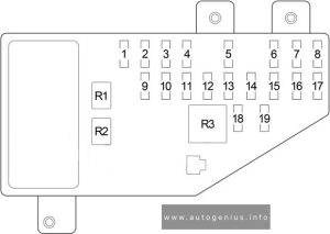
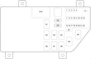
Type 1

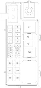
AMC Pacer - fuse box diagram - type 1
AMC Pacer – fuse box diagram – type 1
No.
A
Protected Component
1 20 Turn signal, back-up lights, radio, windshield washer
2 20 Blower motor, air conditioner clutch
3 4 Interlock module circuit, headlight warning buzzer, oil light indicator, park brake, brake failure circuit
4 4 Panel illumination lights
5 14 Interlock module circuit, windshield wiper, park, tail, license and side marker lights
6 20 Stop light and hazard warning flasher
7 9 Dome, courtesy, glove box, trunk and cargo lights, clock

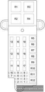
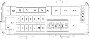
Type 2

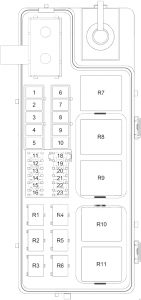
AMC Pacer - fuse box diagram - type 2
AMC Pacer – fuse box diagram – type 2
No.
A
Protected Component
1 10 Parking lights, key/headlight warning buzzer
2 15 Hazard warning, stoplights
3 10 Clock; dome and trunk lights
4 3 Cluster illumination
5  –
6 10 Radio, cigar lighter
7 25 Heater/A/C blower motor, A/C clutch
8 7.5 Gauges, Seat belt warning
9 20 Turn signals, backup lights, windshield washers
10  –
11 30 Power windows
12 25 Heated rear window

Circuit Breaker:

  • Headlights — 20 amp. circuit breaker in headlight switch.
  • Windshield Wiper – 8.25 amp. circuit breaker for windshield wipers and 4.5 amp. breaker for tail gate window wiper, both located at left side of brake support bracket.
  • Power Windows & Tailgate Switches — 20 amp. circuit breakers located in instrument panel.

WARNING: Terminal and harness assignments for individual connectors will vary depending on vehicle equipment level, model, and market.

Honda Insight (2010 – 2014) – fuse box diagram

Honda Insight (2010 – 2014) – fuse box diagram

Year of production: 2010, 2011, 2012, 2014

Passenger Compartment

Honda Insight - fuse box diagram - pasenger compartment
Honda Insight – fuse box diagram – pasenger compartment


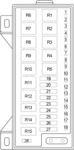
  1. Fuse Box
  2. Tire Pressure Monitoring System (TPMS) Control Unit
  3. Gauge Control Module
  4. Gauge Control Module
  5. Supplemental Restraint System (SRS) Unit
  6. Electronic Power Steering (EPS) Control Unit
  7. Hatch Release Actuator Relay

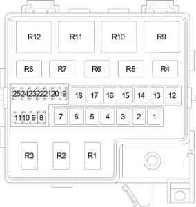
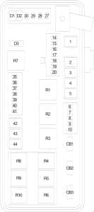
Passenger Compartment Fuse Box

Honda Insight - fuse box diagram - pasenger compartment fuse box
Honda Insight – fuse box diagram – pasenger compartment fuse box


No.
A
Protected Component
1 15 Audio-Navigation Unit (With Navigation), Audio Unit (Without Navigation), Cargo Area Light, Ceiling Light, Data Link Connector (DLC), Gauge Control Module, Immobilizer-Keyless Control Unit, HandsFreeLink Control Unit, Individual Map Light, Multiplex Integrated Control Unit (MICU) (+B BACK UP), Motor Control Module (MCM)
2 7.5 Tire Pressure Monitoring System (TPMS) Control Unit
3 20 Power Window Master Switch
4  –
5 10 Back-up Light, Multiplex Integrated Control Unit (MICU)
6 10 Supplemental Restraint System (SRS) Unit
7 10 Powertrain Control Module – PCM (VBSOL)
8 7.5 Occupant Detection System (ODS) Unit, Front Passenger’s Airbag Cutoff Indicator, Supplemental Restraint System (SRS) Unit
9  –
10 7.5 A/C Compressor Clutch Relay, Blower Motor Relay, Climate Control Unit, Fan Control Relay (A/C Diode A), Optional Connector, Power Mirror Switch, Radiator Fan Relay (A/C Diode A), Rear Window Defogger Relay, Recirculation Control Motor
11 7.5 EPS Control Unit (IG1), VSA Modulator-control Unit (IG1), Yaw Rateacceleration Sensor (With VSA), ABS Modulator-Control Unit (MTR) (Without VSA)
12 10 DC-DC Converter, Evaporative Emission Control (EVAP) Canister Purge Valve, Powertrain Control Module – (Idle Stop Switch), Mass Air Flow (MAF) Sensor, Secondary Heated Oxygen Sensor (HO2S)
13 20 Accessory Power Socket
14 7.5 Audio-Navigation Unit (With Navigation), Audio Unit (Without Navigation), Key Interlock Solenoid, HandsFreeLink Control Unit, MICU (ACC), Optional Connector
15 7.5 Daytime Running Light, Multiplex Integrated Control Unit (MICU)
16 10 Rear Window Wiper Motor
17 20 Front Passenger’s Power Window Motor, Front Passenger’s Power Window Switch Light
18 20 Right Rear Power Window Motor, Power Window Master Switch, Right Rear Power Window Switch Light
19 20 Left Rear Power Window Motor, Power Window Master Switch, Left Rear Power Window Switch Light
20 15 Fuel Pump (PGM-FI Main Relay No.2 (’12-’14)), Immobilizer-Keyless Control Unit, Powertrain Control Module – PCM (IG1) (’12-’14)
21 15 Washer Motor, Multiplex Integrated Control Unit (MICU)
22 7.5 Electrical Load Detector (ELD), Gauge Control Module, Multiplex Integrated Control Unit – MICU (IG1 METER), Motor Control Module (MCM), Shift Lock Solenoid, Tire Pressure Monitoring System (TPMS) Control Unit
23 10 Turn Signal/Hazard Relay, Multiplex Integrated Control Unit (MICU)
24 10 Brake Pedal Position Switch, High Mount Brake Light, Left Brake Light, Right Brake Light, Horn Relay, Multiplex Integrated Control Unit (MICU), Powertrain Control Module (PCM)
25  –
26 10 Air Fuel Ratio (A/F) Sensor, Evaporative Emission Control (EVAP) Canister Vent Shut Valve, Fuse: No. 31 (7.5 A)
27 30 Power Door Lock, Multiplex Integrated Control Unit (MICU)
28 20 Headlamp (Main), Multiplex Integrated Control Unit (MICU)
29 10 Parking Light, Multiplex Integrated Control Unit (MICU)
30 30 Radiator Fan Motor (Radiator Fan Relay), A/C Condenser Fan Motor (Fan Control Relay) (’12-’14)
31 7.5 A/C Condenser Fan Relay (A/C Diode B)
32 10 Right Headlight (Low Beam)
33 20 Ignition Coil Relay, Fuses (Engine Compartment): No.1 (15 A), 2 (15 A)
34 10 Left Headlight (Low Beam)
35 15 Front Passenger’s Door Lock Actuator, Right Rear Door Lock Actuator
36 15 Driver’s Door Lock Actuator, Left Rear Door Lock Actuator
37 30 ABS Modulator-Control Unit (Without VSA), VSA Modulator-Control Unit
38 15 Driver’s Door Lock Actuator
39 15 Crankshaft Position (CKP) Sensor, Camshaft Position (CMP) Sensor, Electronic Throttle Control System (ETCS) Control Relay, Injectors, Powertrain Control Module – PCM (IGP), PGM-FI Main Relay No.1, PGM-FI Main Relay No.2 (Fuel Pump)
40  –
41  –
42 10 Motor Control Module (MCM), MCM Relay No.1, MCM Relay No.2
43 7.5 A/C Compressor (A/C Compressor Clutch Relay)
44 7.5 Starter Cut Relay, Powertrain Control Module – PCM (STS)
45 7.5 Hatch Release Actuator Relay, Hatch Release Actuator
46  –
47 30 A/C Condenser Fan Motor (A/C Condenser Fan Relay), Radiator Fan Motor (Fan Control Relay) (’10-’11)
48 10 Left Headlight (High Beam)
49 15 Front Passenger’s Door Lock Actuator, Right Rear Door Lock Actuator
50 15 Left Rear Door Lock Actuator
51 10 Right Headlight (High Beam)
52 15 Electronic Throttle Control System (ETCS) Control Relay, Powertrain Control Module – PCM (IG1ETCS)
53 10 Intelligent Power Unit (IPU) Module Fan (Motor Control Module (MCM) Relay No.2), Motor Power Inverter (MPI) Module (Motor Control Module (MCM) Relay No.2)
54  –
55 10 Left Power Mirror Defogger, Right Power Mirror Defogger
56 30 Front Wiper, Multiplex Integrated Control Unit (MICU)
57 30 Blower Motor (Blower Motor Relay)
58 30 ABS Modulator-Control Unit (Without VSA), VSA Modulator-Control Unit
59 30 Without Power Mirror Defogger: Rear Window Defogger Relay (Lower Rear Window Defogger, Upper Rear Window Defogger, Noise Reduction Condenser)
40 With Power Mirror Defogger: Rear Window Defogger Relay (Lower Rear Window Defogger, Upper Rear Window Defogger, Noise Reduction Condenser, Fuse: No.55 (10 A))
60 50 Ignition switch
30 Headlamp Washer
Relay
R1 Power Window
R2 Blower Motor
R3 Air Fuel Ratio (A/F) Sensor
R4 Lighting
R5 Ignition Coil
R6 PGM-FI Main No.1
R7 Electronic Throttle Control System (ETCS) Control
R8 Rear Window Defogger
R9 Driver’s Door Unlock
R10 Starter Cut
R11  –
Honda Insight - fuse box diagram - pasenger compartment
Honda Insight – fuse box diagram – pasenger compartment


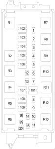
  1. Immobilizer-Keyless Control Unit
  2. Climate Control Unit
  3. Audio-Navigation Unit (With Navigation), Audio Unit (Without Navigation)
  4. HandsFreeLink Control Unit
Honda Insight - fuse box diagram - pasenger compartment
Honda Insight – fuse box diagram – pasenger compartment


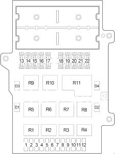
  1. Motor Control Module (MCM)
  2. Motor Control Module (MCM) Relay No.1
  3. Motor Control Module (MCM) Relay No.2

Engine Compartment

Honda Insight - fuse box diagram - engine compartment
Honda Insight – fuse box diagram – engine compartment


  1. ABS Modulator-Control Unit (Without VSA), VSA Modulator-Control Unit
  2. Powertrain Control Module (PCM)
  3. Relay Box No.1
  4. Relay Box No.2

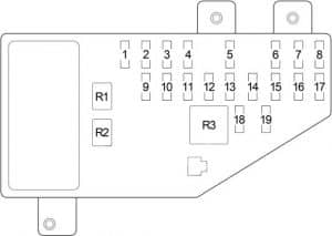
Engine Compartment Relay Box No.1

Honda Insight - fuse box diagram - engine compartment relay box no. 1
Honda Insight – fuse box diagram – engine compartment relay box no. 1
No.
A
Protected Component
1 15 Exhaust Side Ignition Coils
2 15 Intake Side Ignition Coils
Relay
R1 Fan Control
R2 PGM-FI Main No.2 (Fuel Pump)

Engine Compartment Relay Box No.2

Honda Insight - fuse box diagram - engine compartment relay box no. 2
Honda Insight – fuse box diagram – engine compartment relay box no. 2
No.
Protected Component
R1 A/C Condenser Fan
R2 Radiator Fan
R3 A/C Compressor Clutch

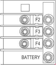
Battery Terminal Fuse Box

Honda Insight - fuse box diagram - battery terminal fuse box
Honda Insight – fuse box diagram – battery terminal fuse box

These fuses are not serviceable; replace the battery terminal fuse box as an assembly.

No.
A
Protected Component
1 100 DC-DC Converter, Lighting Relay, Power Window Relay, Driver’s Door Unlock Relay, Fuses: No. 1, 2, 3, 9, 17, 18, 19, 25, 26, 27, 28, 29, 30, 32, 33, 34, 37, 38, 39, 40, 41, 42, 43, 45, 46, 47, 52, 53, 57, 58, 59, 60
2 60 Electronic Power Steering (EPS) Control Unit
3 20 Fuses: 23, 24


WARNING: Terminal and harness assignments for individual connectors will vary depending on vehicle equipment level, model, and market.
Iveco EuroCargo 6 to 26T (2003) – fuse box diagram

Iveco EuroCargo 6 to 26T (2003) – fuse box diagram

Year of production: 2003

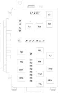
Fuse assembly

Iveco EuroCargo - fuse box diagram
Iveco EuroCargo – fuse box diagram
Position Position Rating Function Power supply
7000/3 1 30 Heated windscreen +30
2 30 Heated windscreen +30
3
4
5
6
7000/1 1 10 Auxiliary heater +30
2 10 Cigaret lighter/Headlight washer/Ceiling light +30
3 10 Fog light/Rotating lamps +30
4 10 Conditioner/Adjustable heated mirrors +30
5 10 Heated seat +15/1
6 10 Reserving lights +15/1
7000/2 1 20 Diesel fuel heating/Loading gate/Diesel fuel prefilter heating/ Window regulator +30
2 20 Sunroof +30
3 20 Trailer ABS +30
4 20 ABS +30
5 5 ABS – ECAS +15/1
6 5 ABS +30

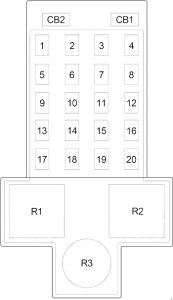
Fuse box

Iveco EuroCargo - fuse box diagram
Iveco EuroCargo – fuse box diagram
No.
A
Protected Component
1 5 Body Control (15) / MICO tachograph / Instruments Cluster
2 5 Cab uncoupled / Immobilizer / Sensor for presence of water in the diesel fuel filter / Head-lamp trim corrector / Bed lights
3 5 MICO tachograph / Body Control (Left low-beam lamp – Right high-beam lamp)
4 5 Body builders
5 5 EDC7
6 5 Trailer takeoff (+15) / Chassis body builder takeoff (+15)
7 10 Central locking / Auxiliary heater / Fridge / Radio
8 10 Body Control (Right low-beam lamp – Left high-beam lamp)
9 10 Cab body builders (+15)
10 10 Body Control (left sidelights and stop lights)
11 10 Body Control (indicators – emergency lights)
12 10 Horn
13 10 Window regulators / Heated windscreen
14 20 Windscreen defrosting electric heater / Conditioner
15 20 Body Control (windscreen wiper — windscreen washer)
16 20 Brake air drier / Adjustable heated rearview mirrors / Control unit
17 10 External light body builders (+58)
18 5 nstruments Cluste
19 10 EDC
20 10 Body Control (right sidelights and rear fog light

WARNING: Terminal and harness assignments for individual connectors will vary depending on vehicle equipment level, model, and market.
Honda Fit (2006 – 2008) – fuse box diagram

Honda Fit (2006 – 2008) – fuse box diagram

Year of production: 2006, 2007, 2008

Passenger Compartment

Honda Fit - fuse box diagram - passenger compartment
Honda Fit – fuse box diagram – passenger compartment
  1. Fuse Box

Passenger Compartment Fuse Box

Honda Fit - fuse box diagram - passenger compartment box
Honda Fit – fuse box diagram – passenger compartment box
No.
A
Circuit
1 10 Back-up Lights, A/T Reverse Relay
2  –
3 10 Gauge Control Module, Keyless Receiver Unit, Security Control Unit, Electronic Power Steering (EPS) Control Unit, Imoes Unit, Tire Pressure Monitoring System (TPMS) Control Unit Control Unit
4 10 Gauge Control Module (Turn Signal/Hazard Circuit)
5  –
6 30 Windshield Wiper Motor, Windshield Washer Motor, Rear Window Washer Motor
7 10 Occupant Detection System (ODS) Unit, Supplemental Restraint System (SRS) Unit
8 7.5 Daytime Running Lights Control Unit
9 20 Rear Window Defogger
10 7.5 Left Mirror, Right Mirror, Rear Window Defogger Switch Indicator Light, Rear Window Defogger Relay, Blower Motor Relay, Radiator Fan Relay, A/C Compressor Clutch Relay, A/C Condenser Fan Relay
11 15 ECM/PCM, Immobilizer Control Unit-Receiver, Fuel Pump
12 10 Power Window Relay, Power Window Master Switch, Rear Window Wiper Motor
13 10 Supplemental Restraint System (SRS) Unit
14 15 PGM-FI Main Relay No.1, PGM-FI Main Relay No.2, ECM/PCM
15 20 Left Rear Window Motor
16 20 Right Rear Window Motor
17 20 Front Passenger’s Window Motor
18 10 Daytime Running Lights Control Unit
7.5 Tire Pressure Monitoring System (TPMS) Control Unit
19  –
20  –
21 20 Fog Lights
22 10 Taillight Relay, Illumination Lights, Left Front Side Marker/Parking Light, Right Front Side Marker/Parking Light, Left Taillight, Right Taillight, License Plate Light, Left Rear Side Marker Light/Taillight, Right Rear Side Marker Light/Taillight
23 10 Air Fuel Ratio (A/F) Sensor, Evaporative Emission Control (EVAP) Canister Vent Shut Valve
24  –
25 7.5 ABS Modulator-Control Unit
26 7.5 Audio Unit, Gauge Control Module, Key Interlock Solenoid
27 15 Accessory Power Socket
28 20 Driver’s Door Lock Actuator, Front Passenger’s Door Lock Actuator, Left Rear Door Lock Actuator, Right Rear Door Lock Actuator, Tailgate Lock Actuator
29 20 Driver’s Window Motor, Power Window Master Switch
30  –
31 7.5 Air Fuel Ratio (A/F) Sensor Relay
32 15 Throttle Actuator Control Module
33 15 Ignition Coil Relay
Relay
R1 Starter Cut
R2 Power Window
R3 Blower Motor
R4 A/T Reverse
R5 Door Lock
R6 Driver’s Door Unlock
R7 Passenger’s Door Unlock / Tailgate Unlock
R8 Taillight
R9 Ignition Coil
R10 PGM-FI Main No.2 (Fuel Pump)
R11 PGM-FI Main No.1
R12 Throttle Actuator Control Module
R13 Rear Window Defogger
R14 Air Fuel Ratio (A/F) Sensor
R15 Fog Light
Honda Fit - fuse box diagram - passenger compartment
Honda Fit – fuse box diagram – passenger compartment
  1. Security Control Unit
  2. Electronic Power Steering (EPS) Control Unit
  3. Tire Pressure Monitoring System (TPMS) Control Unit
  4. Daytime Running Lights Control Unit
  5. Audio Unit
  6. Throttle Actuator Control Module
  7. Low Beam Cut Relay
  8. Daytime Running Lights Relay
  9. Imoes Unit
  10. Keyless Receiver Unit

Engine Compartment

Honda Fit - fuse box diagram - engine compartment
Honda Fit – fuse box diagram – engine compartment
  1. Fuse Box

Engine Compartment Fuse Box No.1

Honda Fit - fuse box diagram - engine compartment box
Honda Fit – fuse box diagram – engine compartment box
No.
A
Protected Component
1 80 Battery, Power Distribution
2 60 Electronic Power Steering (EPS) Control Unit
3 50 Ignition Switch
4 30 ABS Modulator-Control Unit
5 40 Blower Motor
6 40 Fuses: No. 14, 15, 16, 17, 28, 29
7 30 Fuses: No. 18, 21
8 10 Keyless Receiver Unit, Gauge Control Module, Security Control Unit, Immobilizer Control Unit-Receiver, Audio Unit, Imoes Unit
9 30 Fuses: No. 22, 23
10 30 Radiator Fan Motor
11 30 A/C Condenser Fan Motor, A/C Compressor Clutch
12 20 Right Headlight
13 20 Left Headlight, High Beam Indicator
14 10 Gauge Control Module (Turn Signal/Hazard Circuit)
15 30 ABS Modulator-Control Unit
16 15 Horn Relay, Horn, ECM/PCM, Brake Lights, High Mount Brake Light
Relay
R1 Electrical Load Detector (ELD)
R2 Radiator Fan
R3 Horn
R4 Headlight
R5 A/C Condenser Fan
R6 A/C Compressor Clutch

WARNING: Terminal and harness assignments for individual connectors will vary depending on vehicle equipment level, model, and market.
Honda Civic (2006 – 2011) – fuse box diagram

Honda Civic (2006 – 2011) – fuse box diagram

Year of production: 2006, 2007 2008, 2009, 2010, 2011

Passenger Compartment

Honda Civic - fuse box diagram - passenger compartment
Honda Civic – fuse box diagram – passenger compartment
  1. Fuse Box
  2. Gauge Control Module (Tach)
  3. Gauge Control Module (Speedo)
  4. except GX: Console Accessory Power Socket Relay
    Hybrid: Front Accessory Power Socket Relay
    GX: Starter Control Relay
  5. except GX: Front Accessory Power Socket Relay
    Hybrid: Console Accessory Power Socket Relay
    GX: Console Accessory Power Socket Relay
  6. GX: Front Accessory Power Socket Relay
  7. GX: Injector Control Module Relay
  8. SL (’09-’11): Fog Light Relay

Passenger Compartment Fuse Box

Honda Civic - fuse box diagram - passenger compartment fuse box
Honda Civic – fuse box diagram – passenger compartment fuse box
No.
A
Circuit
1 7.5 Power Mirror Switch Light (4-Door), Power Window Relay (without Key-off Operation)
2 15 except Hybrid: Camshaft Position (CMP) Sensor A, Engine/Powertrain Control Module (ECM/PCM), Immobilizer-Keyless Control Unit
15 Hybrid: Powertrain Control Module (PCM), Fuel Pump (PGM-FI Main Relay No.2), Immobilizer-Keyless Control Unit
3 10 Alternator, Engine/Powertrain Control Module (ECM/PCM), Evaporative Emission Control (EVAP) Canister Purge Valve, EVAP Canister Vent Shut Valve, Mass Air Flow (MAF) Sensor
10 DC-DC Converter, Electrical Load Detector (ELD), Evaporative Emission Control (EVAP) Canister Purge Valve, Mass Air Flow (MAF) Sensor, Powertrain Control Module (PCM), Brake Pedal Position Switch, Secondary Heated Oxygen Sensor (HO2S)
4 7.5 ABS or VSA Modulator-Control Unit, Yaw Rate-Lateral Acceleration Sensor (with VSA), Electric Power Steering (EPS) Control Unit
5 15 2-Door: Audio Amplifier
15 Driver’s Seat Heater, Front Passenger’s Seat Heater, Seat Heater Relay
6  –
7 7.5 Tire Pressure Monitoring System (TPMS) Control Unit
8  –
9 7.5 Occupant Detection System (ODS) Unit, Supplemental Restraint System (SRS) Unit, Passenger’s Airbag Cut-Off Indicator
10 7.5 Gauge Control Module (Tach), Power Window Master Switch (2-Door with Auto Up/Auto Down), Back-Up Light Switch (M/T), Shift Lock Solenoid (A/T), Multiplex Integrated Control Unit (MICU), Tire Pressure Monitoring System (TPMS) Control Unit, BCM Module (Hybrid), Interface Box
11 10 Supplemental Restraint System (SRS) Unit
12 10 Right Headlight (High Beam)
13 10 Left Headlight (High Beam)
14 7.5 Audio Unit Light, Dash Lights Brightness Controller Light, Hazard Warning Switch Light, Heater Control Panel Light/HVAC Control Unit Light, Moonroof Switch Light, Passenger’s Airbag Cut-Off Indicator, Select/Reset Switch Light, A/T Gear Position Indicator Panel
Light, Audio Remote Switch Light, Cruise Control Combination Switch Light, Driver’s Seat Heater Switch Light, HFL-Voice Control
Switch Light, Interface Box, Passenger’s Seat Heater Switch Light, VSA OFF Switch Light
15 7.5 Parking Lights, Taillights, License Plate Lights, Side Marker Lights
16 10 Right Headlight (Low Beam)
17 10 Left Headlight (Low Beam)
18 20 High Beam, Multiplex Integrated Control Unit (MICU)
19 15 Parking Lights, Multiplex Integrated Control Unit (MICU)
20  –
21 20 Low Beam, Multiplex Integrated Control Unit (MICU)
22 7.5 Hybrid: A/C Compressor Driver
23 7.5 Starter Switch Signal, Powertrain Control Module (PCM)
24 20 Moonroof Control/Motor
25 20 Power Door Lock, Multiplex Integrated Control Unit (MICU)
26 20 Driver’s Window Motor (Power Window Master Switch)
27  –
28 15 Rear/Console Accessory Power Socket
29 15 Front Accessory Power Socket
30 20 4-Door: Front Passenger’s Window Motor
20 2-Door: Moonroof Switch, Moonroof Control Unit/Motor, Passenger’s Window Motor
31  –
32 20 4-Door: Right Rear Window Motor, Moonroof Switch, Moonroof Control Unit/Motor
33 20 4-Door: Left Rear Window Motor
34  –
35 7.5 Audio Unit, Front Accessory Power Socket, Rear/Console Accessory Power Socket, Stereo Amplifier (2-Door), HandsFreeLink
Control Unit, Ignition Key Switch, Multiplex Integrated Control Unit (MICU), Interface Box
36 10 Heater Control Panel/HVAC Control Unit, Power Mirrors, Recirculation Control Motor, A/C Compressor Clutch Relay, Blower Motor Relay, Power Mirror Defogger Relay, Rear Window Defogger Relay, Cooling Fan Control Relay and Radiator Ran Relay (A/C Diode), AHB Buzzer (Hybrid), Servo Unit (Hybrid)
37 7.5 Daytime Running Light, Multiplex Integrated Control Unit (MICU)
38 30 Front Wiper, Multiplex Integrated Control Unit (MICU)
Relay
R1 Power Window
R2 Fuel Pump (PGM-FI Main 2)
R3 Starter Cut
Honda Civic - fuse box diagram - passenger compartment
Honda Civic – fuse box diagram – passenger compartment
  1. ’08-’11: Tire Pressure Monitoring System (TPMS) Control Unit
  2. Audio/Navigation Unit or Audio Unit
  3. Electric Power Steering (EPS) Control Unit
    GX: Injector Control Module
  4. 2-Door: Audio Amplifier
  5. Supplemental Restraint System (SRS) Unit
  6. ’09-’11: USB Adapter Unit
  7. Heating, Ventilation, and Air Conditioning System (HVAC) Control Unit or Heater Control Panel
  8. Immobilizer-Keyless Control Unit
  9. ’09-’11: HandsFreeLink Control Unit
  10. 4-Door: Audio Amplifier

Engine Compartment

Honda Civic - fuse box diagram - engine compartment
Honda Civic – fuse box diagram – engine compartment
  1. ABS or VSA Modulator Control Unit
  2. Hybrid: Fuse Box No.2
  3. Engine / Powertrain Control Module (ECM/PCM)
  4. Hybrid: Servo Unit
  5. Fuse Box No.1

Engine Compartment Fuse Box No.1

Honda Civic - fuse box diagram - engine compartment fuse box no. 1
Honda Civic – fuse box diagram – engine compartment fuse box no. 1
No.
A
Protected Component
1 100 Battery, Power Distribution
70 Electric Power Steering (EPS) Control Unit
2 50 Ignition Switch
80 except Hybrid: Fuses (Passenger Compartment): 5, 6, 7, 27, 28, 29, 31
80 ’06-’07 (Hybrid): Fuses (Passenger Compartment): 5, 6, 7, 27, 28, 29, 31
60 ’08-’11 (Hybrid): Fuses (Passenger Compartment): 5, 6, 7, 27, 28, 29, 31
3 30 ABS or VSA Modulator-Control Unit
30 except Hybrid: ABS or VSA Modulator-Control Unit
30 Hybrid: ABS Modulator-Control Unit
40 Hybrid: VSA Modulator-Control Unit
4 50 Fuses (Passenger Compartment): 18, 19, 20, 21
40 Fuses (Passenger Compartment): 24, 25, 26, 30, 32, 33
5 40 Servo Unit
6 20 A/C Condenser Fan Relay, A/C Condenser Fan Motor
7 20 M/T: Radiator Fan Relay, Radiator Fan Motor
30 A/T: Radiator Fan Relay, Radiator Fan Motor
8 30 4-Door: Rear Window Defogger Relay, Rear Window Defogger
40 2-Door: Rear Window Defogger Relay, Rear Window Defogger
9 40 Blower Motor Relay, Blower Motor
10 10 Hazard Lights, Multiplex Integrated Control Unit (MICU), Gauge Control Module (Speedo), Gauge Control Module (Tach),
11 15 Air Fuel Ratio (A/F) Sensor No.1, Engine/Powertrain Control Module (ECM/PCM), Vent Shut Solenoid (Hybrid)
12 15 Brake lights, Engine/Powertrain Control Module (ECM/PCM), Horn, Multiplex Integrated Control Unit (MICU)
13 15 Hybrid: Rear Ignition Coils
14 15 Hybrid: Front Ignition Coils
15 7.5 A/C Condenser Fan Relay
16  –
17 15 2-Door: Audio Amplifier
18 15 except Hybrid: Iqnition Coils, Engine/Powertrain Control Module (ECM/PCM)
20 Hybrid: Iqnition Coils, Powertrain Control Module (PCM)
19 15 Crankshaft Position (CKP) Sensor, Camshaft Position (CMP) Sensor B, Engine/Powertrain Control Module (ECM/PCM), Electronic Throttle Control System (ETCS) Control Relay, Injectors, PGM-FI Main Relay No.1 (Fl MAIN), PGM-FI Main Relay No.2 (Fuel Pump) (except Hybrid)
20 7.5 A/C Compressor Clutch Relay, A/C Compressor Clutch
21 15 Electronic Throttle Control System (ETCS) Control Relay, Engine/Powertrain Control Module (ECM/PCM)
22 7.5 Ceiling Light, Map Lights, Trunk Light, Auxiliary Electric Water Pump, Auxiliary Electric Water Pump Relay
23 10 Audio Unit, Data Link Connector (DLC), Gauge Control Module (Tach), Gauge Control Module (Speedo), Hazard Warning Switch, Immobilizer-Keyless Control Unit, Multiplex Integrated Control Unit (MICU), Motor Control Module (MCM) (Hybrid), BCM Module (Hybrid), HandsFreeLink Control Unit
Relay
R1 Radiator Fan
R2 A/C Condenser Fan
R3 Fan Control
R4 Electronic Throttle Control System (ETCS) Control
R5 Blower Motor
R6 Power Mirror Defogger
R7 PGM-FI Main (No.1)
R8 Rear Window Defogger
R9 PGM-FI Subrelay
R10 A/C Compressor Clutch
R11 Ignition Coil

ECM – Engine Control Module (with Manual Transmission)

PCM – Powertrain Control Module (with Automatic Transmission)

Engine Compartment Fuse Box No.2

Honda Civic - fuse box diagram - engine compartment fuse box no. 2
Honda Civic – fuse box diagram – engine compartment fuse box no. 2
No.
A
Protected Component
61 10 BCM Module, Motor Control Module (MCM) Relay No.2, Servo Unit
62 7.5 BCM Module, Motor Control Module (MCM) Relay No.1
63 15 Servo Unit
64  –
Relay
R1 Auxiliary Electric Water Pump
R2 Fuel Pump
Honda Civic - fuse box diagram
Honda Civic – fuse box diagram
  1. ’09-’11: USB Adapter Unit
  2. Hybrid: Motor Control Module (MCM) Relay No.1
  3. Hybrid: Motor Control Module (MCM) Relay No.2
  4. ’07-’10: XM Receiver (with Navigation)
  5. Hybrid: Motor Control Module (MCM)
  6. ’09-’11: HandsFreeLink Control Unit

WARNING: Terminal and harness assignments for individual connectors will vary depending on vehicle equipment level, model, and market.
Honda Accord (2008 – 2012) – fuse box diagram

Honda Accord (2008 – 2012) – fuse box diagram

Year of production: 2008, 2009, 2010, 2011, 2012

Passenger Compartment

Honda Accord - fuse box diagram - passenger compartment
Honda Accord – fuse box diagram – passenger compartment


  1. Fuse Box No.1
  2. Driver’s Junction Box No.2
  3. HandsFreeLink Control Unit
  4. Driver’s Junction Box No.1
  5. Gauge Control Module


Passenger Compartment Fuse Box No.1

Honda Accord - fuse box diagram - passenger compartment fuse box no. 1
Honda Accord – fuse box diagram – passenger compartment fuse box no. 1
No.
A
Circuit
1  –
2 7.5 Power Seat Control Unit
3 15 Washer Motor Relay
4 7.5 Windshield Wiper Motor Relay
5 7.5 Automatic Dimming Inside Mirror, Reverse Relay, Driver’s Multiplex Integrated Control Unit (MICU), Electrical Compass Unit, Gauge Control Module, Left Back-Up Light, Navigation Unit, Passenger’s Multiplex Integrated Control Unit (MICU), Right Back-Up Light, Shift Lock Solenoid (A/T), Tire Pressure Monitoring System (TPMS) Control Unit
6 7.5 VSA Modulator-Control Unit, Yaw Rate-Lateral Acceleration Sensor
7 15 Active Control Engine Mount (ACM) Control Relay (A/T), Alternator, Engine/Powertrain Control Module (ECM/PCM) (BKSWNC), PCM (VBSOL1) (A/T), Engine Mount Control Solenoid Valve (M/T), Electrical Load Detector (ELD), Engine Mount Control Unit (A/T), Evaporative Emission Control (EVAP) Canister Purge Valve, Reverse Lockout Solenoid (M/T)
8 7.5 3.5L: Starter, Engine/Powertrain Control Module (ECM/PCM) (STS)
9 20 Engine/Powertrain Control Module (ECM/PCM) (IG1), Fuel Pump, PGM-FI Main Relay No.2, Immobilizer-Keyless Control Unit
10 10 A/T: Powertrain Control Module (PCM) (VBSOL2)
11 10 Supplemental Restraint System (SRS) Unit
12 7.5 Occupant Detection System (ODS) Unit. Passenger’s Airbag Cutoff Indicator, Supplemental Restraint System (SRS) Unit
13  –
14 10 3.5L+A/T: Engine Mount Control Unit, Active Control Engine Mount (ACM) Control Relay
15 7.5 Daytime Running Lights, Driver’s Multiplex Integrated Control Unit (MICU)
16 7.5 A/C Condenser Fan Relay, Audio-HVAC Display/Subdisplay Unit, Blower Motor Relay, Climate Control Unit, Door Multiplex Control Unit (Power Window Master Switch), Driver’s Climate Control Switch, Driver’s Seat Heater Switch, FAN Control Relay, Front Passenger’s Climate Control Switch, Front Passenger’s Seat Heater Switch, HVAC Control Unit, Navigation Display Unit, Power Mirror Switch, Radiator Fan Relay, Rear Window Defogger Relay, Recirculation Control Motor, Seat Heater Relays (Seat Heater Switch)
17 7.5 Driver’s Multiplex Integrated Control Unit (MICU) (ACC Key Lock)
18 7.5 Audio Unit, Console Accessory Power Socket Relay, Front Accessory Power Socket Relay, HandsFreeLink Control Unit., Front Active Noise Cancellation Microphone, Front HFL-Navigation-ANC Microphone, Interface Dial, Key Interlock Solenoid (A/T), Navigation Display Unit, Navigation Unit
19 20 Driver’s Power Seat Front Up-Down Motor, Driver’s Power Seat Adjustment Switch, Driver’s Power Seat Slide Motor, Power Seat Control Unit (VMP1)
20 20 Moonroof Control Unit/Motor
21 20 Driver’s Power Seat Rear Up-Down Motor, Driver’s Power Seat Adjustment Switch, Driver’s Power Seat Recline Motor, Power Seat Control Unit (VMP2)
22 20 4-Door: Left Rear Power Window Motor (Left Rear Power Window Switch), Power Window Relay
23 15 Front Accessory Power Socket (Front Accessory Power Socket Relay)
24 20 Driver’s Power Window – Door Multiplex Control Unit (Power Window Master Switch)
25 10 Power Door Lock Relay, Driver’s Door Lock Actuator, Left Rear Door Lock Actuator, Trunk Lid Release Actuator, Trunk Lid Release Actuator Relay
26 10 Left Front Fog Light, Driver’s Multiplex Integrated Control Unit (MICU), Front Fog Light Relay
27 10 Left Front Parking Light, Left Front Side Marker Light, License Plate Light(s), Taillights, Taillight Relay, Driver’s Multiplex Integrated Control Unit (MICU)
28 10 Left Headlight High Beam
29 7.5 Tire Pressure Monitoring System (TPMS) Control Unit
30 10 Left Headlight Low Beam
31  –
Relay
R1 PGM-FI Main No.2 (Fuel Pump)
R2 Front Accessory Power Socket
R3 Starter Cut
Honda Accord - fuse box diagram - passenger compartment
Honda Accord – fuse box diagram – passenger compartment


  1. Navigation Display Unit
  2. Climate Control Unit
  3. Audio Amplifier
  4. Fuse Box No.2
  5. Audio/HVAC Subdisplay Unit
  6. Audio Unit


Passenger Compartment Fuse Box No.2

Honda Accord - fuse box diagram - passenger compartment fuse box no. 2
Honda Accord – fuse box diagram – passenger compartment fuse box no. 2
No.
A
Protected Component
1 10 Right Headlight High Beam
2 10 Right Front Parking Light, Passenger’s Multiplex Integrated Control Unit (MICU), Right Front Side Marker Light, Taillight Relay, Fuse (Passenger Compartment Fuse Box No.2): No. 6
3 10 Right Left Front Fog Light, Front Fog Light Relay, Passenger’s Multiplex Integrated Control Unit (MICU)
4 10 Right Headlight Low Beam
5  –
6 7.5 A/T Gear Position Indicator Panel Light (A/T), Ambient Light, Audio-HVAC Display/Subdisplay Unit Light, Climate Control Unit Light(, Driver’s Seat Heater Switch Light, Driver’s Climate Control Switch, Front Passenger’s Seat Heater Switch Light. Glove Box Light, Hazard Warning Switch/Passenger’s Airbag Cutoff Indicator Light, HomeLink Unit, HVAC Control Unit Light, Moonroof Switch Light, Navigation Display Unit, Navigation Unit, Passenger’s Climate Control Switch, Steering Wheel Switch Lights, VSA OFF Switch Light
7  –
8 20 Front Passenger’s Power Seat Recline Motor (Front Passenger’s Power Seat Adjustment Switch)
9 20 Front Passenger’s Power Seat Slide Motor (Front Passenger’s Power Seat Adjustment Switch)
10 10 Power Door Lock Relay, Front Passenger’s Door Lock Actuator, Right Rear Door Lock Actuator
11 20 4-Door: Right Rear Power Window Motor (Right Rear Power Window Switch)
12 15 Console Accessory Power Socket, Console Accessory Power Socket Relay
13 20 Front Passenger’s Power Window Switch
14  –
15 20 Audio Amplifier
16  –
17  –
18 10 Driver’s Lumbar Support Motor (Driver’s Lumbar Support Switch)
19 15 Seat Heater Relays, Driver’s Seat Heater, Front Passenger’s Seat Heater
20  –
21  –
22  –
Honda Accord - fuse box diagram - passenger compartment
Honda Accord – fuse box diagram – passenger compartment


  1. Immobilizer-Keyless Control Unit
  2. Tire Pressure Monitoring System (TPMS) Control Unit
  3. Center Junction Box
  4. Supplemental Restraint System (SRS) Unit
  5. USB Adapter Unit
  6. Console Accessory Power Socket Relay
  7. V6+A/T: Engine Mount Control Unit


Engine Compartment

Honda Accord - fuse box diagram - engine compartment
Honda Accord – fuse box diagram – engine compartment


  1. Fuse Box
  2. M/T: Engine Control Module
    A/T: Powertrain Control Module
  3. VSA Modulator Control Unit

Engine Compartment Fuse Box

Honda Accord - fuse box diagram - engine compartment fuse box
Honda Accord – fuse box diagram – engine compartment fuse box
No.
A
Protected Component
1.1 120 3.5L: Battery, Power Supply
100 2.4L: Battery, Power Supply
1.2 40 Fuse (Passenger Compartment Fuse Box No.2): No. 8, 9, 10, 11, 12, 13
2.1  –
2.2 40 VSA Modulator Control Unit
2.3 30 VSA Modulator Control Unit
2.4 40 Fuse (Passenger Compartment Fuse Box No.2): No. 15, 17, 18, 19
2.5  –
2.6  –
3.1 50 Ignition Switch
3.2 40 2.4L (LX-S, LX-P PZEV, LX (’11-’12)): Fuse (Passenger Compartment Fuse Box No.1): No. 18, 19, 20, 21, 22, 23, 24, 25
3.3 30 Fuse (Passenger Compartment Fuse Box No.2): No. 1, 2, 3, 4
3.4 60 3.5L: 2.4L (except ↑): Fuse (Passenger Compartment Fuse Box No.1): No. 18, 19, 20, 21, 22, 23, 24, 25
3.5 30 Fuse (Passenger Compartment Fuse Box No.1): No. 26, 27, 28, 29, 30
3.6 30 3.5L: Radiator Fan Relay, Radiator Fan Motor
30 2.4L: A/C Condenser Fan Motor, A/C Condenser Fan Relay
3.7 30 Windshield Wiper High/Low Relay, Windshield Wiper Motor Intermittent Relay, Windshield Wiper Motor, Windshield Wiper Motor Relay
3.8 30 3.5L: A/C Condenser Fan Relay, A/C Condenser Fan Motor
30 2.4L: Radiator Fan Relay, Radiator Fan Motor
4 40 Rear Window Defogger Relay, Glass Antenna Coil, Noise Reduction Condenser
5 20 2.4L: Sub Fan Motor
6  –
7  –
8 40 Blower Motor, Blower Motor Relay
9 15 Hazard Warning Switch, Driver’s Multiplex Integrated Control Unit (MICU)
10 20 Brake Pedal Position Switch, Driver’s Multiplex Integrated Control Unit (MICU), Engine/Powertrain Control Module (ECM/PCM), High Mount Brake Light, Horn Relay, Horns, Left Brake Light, Right Brake Light
11  –
12  –
13 15 Ignition Coil Relay, Ignition Coils
14 15 3.5L: PGM-FI Subrelay, Evaporative Emission Control (EVAP) Canister Vent Shut Valve, Front Air Fuel Ratio (A/F) Sensor (Bank 1, Sensor 1), Front Secondary Heated Oxygen Sensor (HO2S) (Bank 1, Sensor 2), Rear Air Fuel Ratio (A/F) Sensor (Bank 2, Sensor 1), Rear Secondary Heated Oxygen Sensor (HO2S) (Bank 2, Sensor 2), Fuse (Engine Compartment Fuse Box): No. 21
15 2.4L: PGM-FI Subrelay, Air Fuel Ratio (A/F) Sensor, Engine/Powertrain Control Module (ECM/PCM)
15 10 Audio Unit, Audio-HVAC Display/Subdisplay Unit, Data Link Connector (DLC), Driver’s Door Courtesy Light (4-Door), Driver’s Multiplex Integrated Control Unit (MICU) (VBU), Front Active Noise Cancellation Microphone, Front HFL-Navigation-ANC Microphone, Front Passenger’s Door Courtesy Light (4-Door), Gauge Control Module, HandsFreeLink Control Unit, Immobilizer-Keyless Control Unit, Navigation Display Unit, Navigation Unit. Passenger’s Multiplex Integrated Control Unit (MICU) (VBU), Power Seat Control Unit, Power Window Master Switch
16 7.5 Ceiling Light, Driver’s Vanity Mirror Light, Front Individual Map Light, HomeLink Unit, Ignition Key Light, Passenger’s Vanity Mirror Light, Trunk Light
17 15 Crankshaft Position (CKP) Sensor, Camshaft Position (CMP) Sensor, Engine/Powertrain Control Module (ECM/PCM) (IGP), Electronic Throttle Control System (ETCS) Control Relay, Injectors, Mass Airflow (MAF) Sensor, PGM-FI Main Relay No.1, PGM-FI Main Relay No.2 (Fuel Pump)
18 15 Electronic Throttle Control System (ETCS) Control Relay, Engine/Powertrain Control Module (ECM/PCM)
19 7.5 3.5L: Engine/Powertrain Control Module (ECM/PCM) (VBUM)
20 7.5 A/C Compressor Clutch, A/C Compressor Clutch Relay
21 7.5 3.5L: Radiator Fan Relay
7.5 2.4L: A/C Condenser Fan Relay
Relay
R1 Blower Motor
R2 Horn
R3 PGM-FI Main No.1
R4 PGM-FI Sub
R5 Ignition Coil
R6 Electronic Throttle Control System (ETCS) Control
R7  –
R8 Rear Window Defogger
R9 A/C Compressor Clutch
Honda Accord - fuse box diagram
Honda Accord – fuse box diagram


  1. Navigation Unit
  2. Moonroof Control Unit/Motor
  3. XM Receiver
  4. Electrical Compass Unit


WARNING: Terminal and harness assignments for individual connectors will vary depending on vehicle equipment level, model, and market.
Honda Civic (1980 – 1983) – fuse box diagram

Honda Civic (1980 – 1983) – fuse box diagram

Year of production: 1980, 1981, 1982, 1983

Passenger Compartment Fuse Box

Honda Civic - fuse box diagram - passenger compartment
Honda Civic – fuse box diagram – passenger compartment
No.
A
Circuit
2 10 Right Headlight Low Beam
3 10 Left Headlight Low Beam
4 10 Right Headlight High Beam, High Beam Indicator Light
5 10 Left Headlight High Beam
6 10 Regulator, Fuel Pump Cut-Off Relay, Primary Cut-Off Solenoid, Vacuum Holding Solenoid Valve, EGR Control Solenoid Valves, Speed Sensor, Power Valve Control Solenoid Valve, Control Switch Solenoid Valve, Idle Compensation Unit (Manual Only), Idle Compensation Solenoid Valve (Manual Only), Control Unit (1300 5-Speed Only), T/C Solenoid Valve (1300 5-Speed Only), Upshift Indicator (1300 5-Speed Only)
7 15 Wiper & Washer Motor
8 10 Turn Signal Relay & Lights, Back-Up Lights, Gauges, Warning Lights, Seat Belt Buzzer
9 10 Interior Light, Trunk Light, Cigarette Lighter, Clock, Key Buzzer
10 15 Brakelights, Horn, Hazard Flasher/Relay
11 15 Taillights, Side Marker Lights, Parking & License Lights, Gauge Lights, Ignition Switch Light, Heater Panel Light, A/T Console Light (Automatic Only)
12 15 Rear Window Defroster
13 15 Heater Motor
14 15 Cooling Fan Motor
15 10 Radio
16 10 Cranking Solenoid Valve, Cranking Leak Solenoid Valve

Engine Compartment

Honda Civic - fuse box diagram - engine compartment
Honda Civic – fuse box diagram – engine compartment

Fuse panel is located in engine compartment beside battery

No.
A
Circuit
1 55 Main Fuse

WARNING: Terminal and harness assignments for individual connectors will vary depending on vehicle equipment level, model, and market.
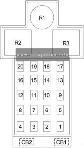
Honda CR-X (1988 – 1991) – fuse box diagram

Honda CR-X (1988 – 1991) – fuse box diagram

Year of production: 1988, 1989, 1990, 1991

Passenger compartment fuse box

Honda C-RX - fuse box - passenger compartment
Honda C-RX – fuse box – passenger compartment
No. A Circuits
1 10 Integrated Control unit, Combination Switch, Gauge Assembly, Back-Up Lights Switch, Shift Position Console Switch, Clock (’90), Shift Lock Solenoid (’90), Interlock Control Unit (’90), Automatic Seat Belts
2 10 Starter Solenoid, PGM-FI Main Relay, PGM-FI Electronic Control Unit, Integrated Control Unit
3 20 Power Door Locks
4 10 Right Headlights High Beam, High Beam Indicator Light, Daytime Running Lights Relay
5 10 Left Headlight High Beam
6 30 Sun Roof Motor
7 10 Rear Lights
8 10 Integrated Control Unit, Interioe & Exterior Lighting
9
10 10 Left Headlight Low Beam
11 10 Right Headlight Low Beam
12 15 Integrated Control Unit, Luggage Compartment Light, Dome Light, Igniotion Switch, Clock, Radio, Cigarette Lighter
13 15 Power Windows, Windshield Wipers & Washer, Sun Roof Relay (’90), Integrated Control Unit, Combination Switch (’90 CRX)
20 Power Windows, Windshield Wipers & Washer, Sun Roof Relay (’90), Integrated Control Unit, Combination Switch (’90 CRX)
14 10 Civic: Gauge Assembly, Engine Sensor & Controls
10 Wagon, CRX: Gauge Assembly, Engine Sensor & Control, PGM-FI Main Relay, PGM-FI ECU, Fuel Pump, ELD Unit, EACV
15 15 Cooling Fan Motor (except 4WD A/T Wagon), Cooling Fan Relay
16 10 Daytime Running Lights
17 10 Radio, Cigarette Lighter Relay (’90)
18 10 Rear Window Defogger, Power Door Mirrors, Air Conditioning
19 30 Blower Motor
20 20 Right Front Power Window
21 20 Left Front Power Window
22 20 Right Rear Power Window
23 20 Left Rear Power Window

Engine Compartment Fuse Box

Honda CT X - fuse box diagram - engine compartment
Honda CT X – fuse box diagram – engine compartment
No. A Circuits
1 60 Power Distribution
2 50 Dash Fuse Box
3 40 Dash Fuse Box, Exterior Lighting
4 10 PGM-FI Electronic Control Unit, Hazard Lights, A/T Control Unit (Wagon), Integrated Control Unit (’90), Automatic Shoulder Belts (’90)
5 15 Horns, Brakelights, A/T Control Unit (Wagon), Key Interlock Solenoid (A/T Only), Seat Belt Retractors (’90)
6 20 Rear Window Defogger
7 15 PGM-FI Main Relay
8 15 A/C Compressor Clutch, Condenser Fan Relay

WARNING: Terminal and harness assignments for individual connectors will vary depending on vehicle equipment level, model, and market.

Honda CR-X (1984 – 1987) – fuse box diagram

Honda CR-X (1984 – 1987) – fuse box diagram

Year of production: 1984, 1985, 1986, 1987

Passenger Compartment Fuse Box

Honda Civic - fuse box diagram - passenger compartment
Honda Civic – fuse box diagram – passenger compartment
No.
A
Circuit
1 10 Brake Warning System, Charging System
2 15 Wipers & Washers, Sun Roof
3 10 Back-Up Lights, Clock & Gauges, Seat Belt Warning, Tachometer & Warning Indicators, Turn Lights (CRX), Upshift Indicator (CRX), 4WD Indicator
4 10 Emission Controls, Radiator Fan, Alternator Control Unit (’84 CRX 1300), Upshift Indicator (’84 CRX 1300), Charge Indicator (’86-’87 Civic), Charging System (’86-’87 CRX), 4WD Controls
5 10 Headlights
6 10 Headlights
7 10 Headlights
8 10 Headlights
9 15 Brakelights, Horn
10  –
11 15 Trunk/Hatch Light, Interior Light, Key Warning, Clock & Radio, Cigarette Lighter, Front Marker Lights (’86-’87)
12 15 Dash & Console Lights, Front Marker Lights (’84-’85), Rear Marker Lights, License Light, Park Lights, Taillights, Emission Control Unit (’86-’87 Wagon)
13 15 Air Conditioner, Radiator Fan
14 20 Air Conditioner, Blower & Heater Controls, Rear Window Defogger
15 10 Radio
16 20 Air Conditioner, Radiator Fan, Sun Roof
30 ’86-’87 (CRX): Air Conditioner, Radiator Fan, Sun Roof
17 20 Rear Window Defogger
18 15 ’86-’87 (CRX): Emission Controls
19 15 Civic Wagon: Hatch Release

Engine Compartment

Honda CR-X - fuse box diagram - engine compartment
Honda CR-X – fuse box diagram – engine compartment

Fuse panel is located in engine compartment beside battery

No.
A
Circuit
1 55 Main Power Distribution & Hazard Fuse
2 45 Ignition Switch
3 45 Dash Fuse Box, Headlights

WARNING: Terminal and harness assignments for individual connectors will vary depending on vehicle equipment level, model, and market.
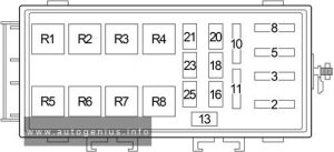
Honda Civic (1984 – 1987) – fuse box diagram

Honda Civic (1984 – 1987) – fuse box diagram

Year of production: 1984, 1985, 1986, 1987

Passenger Compartment Fuse Box

Honda Civic - fuse box diagram - passenger compartment
Honda Civic – fuse box diagram – passenger compartment
No.
A
Circuit
1 10 Brake Warning System, Charging System
2 15 Wipers & Washers, Sun Roof
3 10 Back-Up Lights, Clock & Gauges, Seat Belt Warning, Tachometer & Warning Indicators, Turn Lights (CRX), Upshift Indicator (CRX), 4WD Indicator
4 10 Emission Controls, Radiator Fan, Alternator Control Unit (’84 CRX 1300), Upshift Indicator (’84 CRX 1300), Charge Indicator (’86-’87 Civic), Charging System (’86-’87 CRX), 4WD Controls
5 10 Headlights
6 10 Headlights
7 10 Headlights
8 10 Headlights
9 15 Brakelights, Horn
10  –
11 15 Trunk/Hatch Light, Interior Light, Key Warning, Clock & Radio, Cigarette Lighter, Front Marker Lights (’86-’87)
12 15 Dash & Console Lights, Front Marker Lights (’84-’85), Rear Marker Lights, License Light, Park Lights, Taillights, Emission Control Unit (’86-’87 Wagon)
13 15 Air Conditioner, Radiator Fan
14 20 Air Conditioner, Blower & Heater Controls, Rear Window Defogger
15 10 Radio
16 20 Air Conditioner, Radiator Fan, Sun Roof
30 ’86-’87 (CRX): Air Conditioner, Radiator Fan, Sun Roof
17 20 Rear Window Defogger
18 15 ’86-’87 (CRX): Emission Controls
19 15 Civic Wagon: Hatch Release

Engine Compartment

Honda Civic - fuse box diagram - engine compartment
Honda Civic – fuse box diagram – engine compartment

Fuse panel is located in engine compartment beside battery

No.
A
Circuit
1 55 Main Power Distribution & Hazard Fuse
2 45 Ignition Switch
3 45 Dash Fuse Box, Headlights

WARNING: Terminal and harness assignments for individual connectors will vary depending on vehicle equipment level, model, and market.