Ford E-Series E-350 E350 (1995 – 2014) – fuse box diagram

Ford E-Series E-350 E350 (1995 – 2014) – fuse box diagram

Year of production: 1995, 1996, 1997, 1998, 1999, 2000, 2001, 2002, 2003, 2004, 2005, 2006, 2007, 2008, 2009, 2010, 2011, 2012, 2013, 2014

Fuses and circuit breakers specification

Ford E-Series E-150 - fuse box
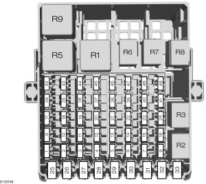
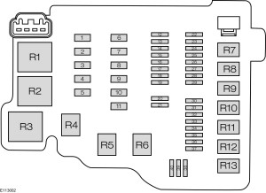
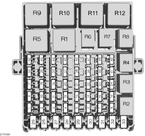
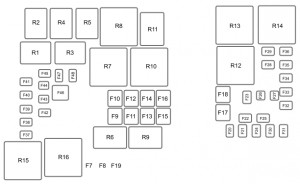
Ford E-Series E-350 – fuse box
Fuse/CB Ampere rating [A] Description
1 15 Brake pressure switch, DLC, PSOM, speed control, stop/hazard/turn lamp
2 30 Wiper control module, windshield wiper motor
3 Not used
4 20 Flash-to-pass, instrument illumination, license lamps, head and park lamps
5 15 Air bag module, auxiliary battery relay, back-up lamps, daytime runnin lamps (DRL) module, hazard lamps, shift lock actuator, transmission control switch, turn lamps
6 20 Accessory tap, anti-theft module, illuminated entry, remote keyless entry module, speed control, trailer battery charge relay
7 10 Anti-theft module, transmission range sensor, park/neutral position module (PCM)
8 15 Anti-theft indicator, courtesy lamp switch, dome/map lamp, illuminated entry, power mirrors, radio memory, remote keyless entry module, visor lamps
9 15 Air conditioner switch
10 25 Cigar lighter, power amplifier, rear power outlet
11 15 Headlamp switch, radio
12 20 CB Anti-theft module, power door locks, memory lock module
13 5 Instrument panel illumination lamps
14 20 CB Power windows
15 20 Air bad module
16 30 Modified vehicle power, power lumbar seats
17 20 Programmable speedometer/odometer module (PSOM), rear anti-lock brake system (RABS)
18 15 Instrument panel warning lamps, warning chime


Circuit protected Location Size
Alternator Starter motor relay 18 GA
Alternator Starter motor relay 12 GA (2)
Glow plugs right bank (diesel) Starter motor relay 14 GA
Glow plugs left bank (diesel) Starter motor relay 14 GA
Powertrain control module (diesel) Starter motor relay 16 GA
20 GA
Ignition switch Power distribution box 60 A fuse
Trailer tow Power distribution box 40 A fuse
Trailer tow Power distribution box 30 A fuse
Fuse panel Power distribution box 60 A fuse
Aux. panel Power distribution box 50 A fuse
Blower motor Power distribution box 60 A fuse
Modified Vehicle Power distribution box 50 A fuse
Electric brake Power distribution box 20 A fuse
Driver’s power seat/lumbar Power distribution box 50 A fuse
Turn signal – RH (trailer tow) Power distribution box 10 A fuse
Turn signal – LH (trailer tow) Power distribution box 10 A fuse
Running lights (trailer tow) Power distribution box 10 A fuse
Horn Power distribution box 15 A fuse
Trailer tow & aux. batt. relay Power distribution box 60 A fuse
Fuel pump (gas engine only) Power distribution box 30 A fuse
Powertrain control module Power distribution box 30 A fuse
Underhood lamp Power distribution box 15 A fuse

Power distibution box

Ford E-Series E-150 - power distribution box
Ford E-Series E-350 – power distribution box

Non-fuse panel circuit protection

Circuit protected Type of protection Location
Glow plug right bank 14 Gauge Fuse link Starter motor relay
Glow plug left bank 14 Gauge Fuse link Starter motor relay
Alternator 18 Gauge Fuse link Starter motor relay
Alternator 12 Gauge Fuse link (2) Starter motor relay
Disel PCMRealy/KAM 16 Gauge20 GaugeFuse link Starter motor relay

WARNING: Terminal and harness assignments for individual connectors will vary depending on vehicle equipment level, model, and market.

Ford E-Series E-250 E250 (1995 – 2014) – fuse box diagram

Ford E-Series E-250 E250 (1995 – 2014) – fuse box diagram

Year of production: 1995, 1996, 1997, 1998, 1999, 2000, 2001, 2002, 2003, 2004, 2005, 2009, 2007, 2008, 2009, 2010, 2011, 2012, 2013, 2014

Fuses and circuit breakers specification

Ford E-Series E-150 - fuse box
Ford E-Series E-250 – fuse box
Fuse/CB Ampere rating [A] Description
1 15 Brake pressure switch, DLC, PSOM, speed control, stop/hazard/turn lamp
2 30 Wiper control module, windshield wiper motor
3 Not used
4 20 Flash-to-pass, instrument illumination, license lamps, head and park lamps
5 15 Air bag module, auxiliary battery relay, back-up lamps, daytime runnin lamps (DRL) module, hazard lamps, shift lock actuator, transmission control switch, turn lamps
6 20 Accessory tap, anti-theft module, illuminated entry, remote keyless entry module, speed control, trailer battery charge relay
7 10 Anti-theft module, transmission range sensor, park/neutral position module (PCM)
8 15 Anti-theft indicator, courtesy lamp switch, dome/map lamp, illuminated entry, power mirrors, radio memory, remote keyless entry module, visor lamps
9 15 Air conditioner switch
10 25 Cigar lighter, power amplifier, rear power outlet
11 15 Headlamp switch, radio
12 20 CB Anti-theft module, power door locks, memory lock module
13 5 Instrument panel illumination lamps
14 20 CB Power windows
15 20 Air bad module
16 30 Modified vehicle power, power lumbar seats
17 20 Programmable speedometer/odometer module (PSOM), rear anti-lock brake system (RABS)
18 15 Instrument panel warning lamps, warning chime
Circuit protected Location Size
Alternator Starter motor relay 18 GA
Alternator Starter motor relay 12 GA (2)
Glow plugs right bank (diesel) Starter motor relay 14 GA
Glow plugs left bank (diesel) Starter motor relay 14 GA
Powertrain control module (diesel) Starter motor relay 16 GA
20 GA
Ignition switch Power distribution box 60 A fuse
Trailer tow Power distribution box 40 A fuse
Trailer tow Power distribution box 30 A fuse
Fuse panel Power distribution box 60 A fuse
Aux. panel Power distribution box 50 A fuse
Blower motor Power distribution box 60 A fuse
Modified Vehicle Power distribution box 50 A fuse
Electric brake Power distribution box 20 A fuse
Driver’s power seat/lumbar Power distribution box 50 A fuse
Turn signal – RH (trailer tow) Power distribution box 10 A fuse
Turn signal – LH (trailer tow) Power distribution box 10 A fuse
Running lights (trailer tow) Power distribution box 10 A fuse
Horn Power distribution box 15 A fuse
Trailer tow & aux. batt. relay Power distribution box 60 A fuse
Fuel pump (gas engine only) Power distribution box 30 A fuse
Powertrain control module Power distribution box 30 A fuse
Underhood lamp Power distribution box 15 A fuse

Power distibution box

Ford E-Series E-150 - power distribution box
Ford E-Series E-250 – power distribution box

Non-fuse panel circuit protection

Circuit protected Type of protection Location
Glow plug right bank 14 Gauge Fuse link Starter motor relay
Glow plug left bank 14 Gauge Fuse link Starter motor relay
Alternator 18 Gauge Fuse link Starter motor relay
Alternator 12 Gauge Fuse link (2) Starter motor relay
Disel PCMRealy/KAM 16 Gauge20 GaugeFuse link Starter motor relay

WARNING: Terminal and harness assignments for individual connectors will vary depending on vehicle equipment level, model, and market.
Ford E-Series E-150 (1992 – 1996) – fuse box diagram

Ford E-Series E-150 (E150; E 150) (1992 – 1996) – fuse box diagram

Year of production: 1992, 1993, 1994, 1995, 1996

Fuses and circuit breakers specification

Ford E-Series E-150 - fuse box
Ford E-Series E-150 – fuse box
Fuse/CB Ampere rating [A] Description
1 15 Brake pressure switch, DLC, PSOM, speed control, stop/hazard/turn lamp
2 30 Wiper control module, windshield wiper motor
3 Not used
4 20 Flash-to-pass, instrument illumination, license lamps, head and park lamps
5 15 Air bag module, auxiliary battery relay, back-up lamps, daytime runnin lamps (DRL) module, hazard lamps, shift lock actuator, transmission control switch, turn lamps
6 20 Accessory tap, anti-theft module, illuminated entry, remote keyless entry module, speed control, trailer battery charge relay
7 10 Anti-theft module, transmission range sensor, park/neutral position module (PCM)
8 15 Anti-theft indicator, courtesy lamp switch, dome/map lamp, illuminated entry, power mirrors, radio memory, remote keyless entry module, visor lamps
9 15 Air conditioner switch
10 25 Cigar lighter, power amplifier, rear power outlet
11 15 Headlamp switch, radio
12 20 CB Anti-theft module, power door locks, memory lock module
13 5 Instrument panel illumination lamps
14 20 CB Power windows
15 20 Air bad module
16 30 Modified vehgivle power, power lumbar seats
17 20 Programmable speedometer/odometer module (PSOM), rear anti-lock brake system (RABS)
18 15 Instrument panel warning lamps, warning chime


Circuit protected Location Size
Alternator Starter motor relay 18 GA
Alternator Starter motor relay 12 GA (2)
Glow plugs right bank (diesel) Starter motor relay 14 GA
Glow plugs left bank (diesel) Starter motor relay 14 GA
Powertrain control module (diesel) Starter motor relay 16 GA
20 GA
Ignition switch Power distribution box 60 A fuse
Trailer tow Power distribution box 40 A fuse
Trailer tow Power distribution box 30 A fuse
Fuse panel Power distribution box 60 A fuse
Aux. panel Power distribution box 50 A fuse
Blower motor Power distribution box 60 A fuse
Modified Vehicle Power distribution box 50 A fuse
Electric brake Power distribution box 20 A fuse
Driver’s power seat/lumbar Power distribution box 50 A fuse
Turn signal – RH (trailer tow) Power distribution box 10 A fuse
Turn signal – LH (trailer tow) Power distribution box 10 A fuse
Running lights (trailer tow) Power distribution box 10 A fuse
Horn Power distribution box 15 A fuse
Trailer tow & aux. batt. relay Power distribution box 60 A fuse
Fuel pump (gas engine only) Power distribution box 30 A fuse
Powertrain control module Power distribution box 30 A fuse
Underhood lamp Power distribution box 15 A fuse


Power distibution box

Ford E-Series E-150 - power distribution box
Ford E-Series E-150 – power distribution box

Non-fuse panel circuit protection

Circuit protected Type of protection Location
Glow plug right bank 14 Gauge Fuse link Starter motor relay
Glow plug left bank 14 Gauge Fuse link Starter motor relay
Alternator 18 Gauge Fuse link Starter motor relay
Alternator 12 Gauge Fuse link (2) Starter motor relay
Disel PCMRealy/KAM 16 Gauge20 GaugeFuse link Starter motor relay


WARNING: Terminal and harness assignments for individual connectors will vary depending on vehicle equipment level, model, and market.
 

Ford Contour (1996 – 2000) – fuse box diagram

Ford Contour (1996 – 2000) – fuse box diagram

Year of production: 1996, 1997, 1998, 1999, 2000

Power distribution box fuses and relays

Ford Contour - fuse box - power distribution box
Ford Contour – fuse box – power distribution box

Fuses

Fuse Ampere rating [A] Description
1 80 Main power supply
2 60 Engine cooling fan
3 60 ABS braking system
4 20 Daytime running lights, ignition
5 15 Fog lamp
6 Not used
7 30 ABS braking system
8 30 Air pump
9 20 EEC module
10 20 Ignition switch
11 3 EEC memory
12 15 Hazard flasher, horn
13 15 HEGO sensor
14 15 Fuel pump
15 10 Right low beam
16 10 Left low beam
17 10 Right high beam
18 10 Left high beam


Relays

Relay Relay color Description
R1 white Daytime running lights (Canada)
R2 black High speed engine cooling fan
R3 blue A/C wide open throttle
R4 yellow A/C clutch relay
R5 dark green Engine cooling fan
R6 yellow Starter
R7 brown Horn
R8 brown Fuel pump
R9 white Low beam
R10 white High beam
R11 brown PCM module
D1 black Reverse voltage protection


Instrument panel fuse

Ford Contour - fuse box -instrument panel fuses
Ford Contour – fuse box -instrument panel fuses

Fuses

Fuse Ampere rating [A] Description
19 7,5 Heated rear view mirrors
20 10 CB Wipers
21 40 Power windows
22 7,5 ABS module
23 15 Backup lamps
24 15 Brakelamps
25 20 Door locks
26 7,5 Main light
27 15 Cigar lighter
28 30 Power seats
29 30 Rear window defrost
30 7,5 Engine management system
31 7,5 Instrument panel illumination
32 7,5 Radio
33 7,5 Left-hand parking lamps
34 7,5 Courtesy lamps
35 7,5 Right-hand parking lamps
36 10 Air bag
37 30 Blower motor
38 Not used


Relays

Relay Color Description
R12 white Courtesy lights
R13 yellow Rear window defroster
R14 yellow Heater fan motor
R15 green Wipers
R16 black Ignition
D2 black Reverse voltage protection
Relays outside the fuse box
R17 Not used
R18 black Express down windows
R19 blue Speed control cut-out
R20 Not used
R21 Not used
R22 white Fog lamps
R23 black Turn signal
R24 white Left panic alarm flasher
R25 white Right panic alarm flasher
R26 Not used
R27 Not used
R28 Not used
R29 brown Door lock control

WARNING: Terminal and harness assignments for individual connectors will vary depending on vehicle equipment level, model, and market.
Ford Bronco 5th Generation (1992 – 1996) – fuse box diagram

Ford Bronco 5th Generation (1992 – 1996) – fuse box

Year of production: 1992, 1993, 1994, 1995, 1996

Fuse panel

Ford Bronco 5th generation - fuse box
Ford Bronco 5th generation – fuse box


Fuse/CB Ampere rating [A] Desciption
1 30 Heater/air conditioner blower
2 30 Wiper/washer
3 Not used
4 15 Exterior lamps, instrument illumination, keyless entry, warning buzzer/chime module
5 10 Air bag restraint
6 15 Air conditioner clutch, remote/keyless entry
7 15 Rear window defrost, turn lamps
8 15 Courtesy/lamps, electric outside mirrors, engine compartment lamp, keyless entery, speedometer, sun visior mirror illumination, warning buzzer/chime module
9 25 Power point
10 4 Instrument illumination
11 15 Radio, radio display dimmer
12 20 Circuit breaker Electronic shift motor 4-wheel drive, power door locks, power lumbar, tailgate power window
13 15 Anti-lock brakers, brake shift interlock, speed control, stop/hazard lamps, stop sense for electronic engine control
14 20 Circuit breaker Power window, tailgate power window: instrument panel switch
15 Not used
16 15 Cigarette lighter
17 10 Electronic transmission, gauges, tachometer, warning buzzer/chime module, warning indicators
18 10 Air bag restraint, automatic day/night mirror, brake shift interlock, electronic shift module 4-wheel drive, overhead console, speedometer


Power distribution box

Ford Bronco 5th generation - power distribution
Ford Bronco 5th generation – power distribution


Fuse/CB/relay Ampere rating [A] Description
1 20 Audio power
2 30 Anit-lock brakes
3 30 Headlamps flash-t0-pass, daytime running lamps (Canada only), horn, speed control
4 25 Trailer back-up lamps, trailer running lamps
5 15 Anit-lock brakes, back-up lamps, daytime running lamp module (DRL) (Canada only), speed control, trailer battery charge relay
6 10 Trailer right-hand stop/turn lamp
7 10 Trailer left-hand stop/turn lamp
8 30 maxi Anti-lock brakes
9 20 maxi Fuel pump relay coil, powertrain control system
10 20 maxi Instrument panel fuses (15,18), starter relay coil
11 Not used
12 Diode Powertrain control system raly
13 50 maxi Instrument panel fuses (5,9,13)
14 30 maxi Rear window defroster
15 50 maxi Instrument panel fuses (1,7), power netword box: fuse 5
16 20 maxi Fuel pump feed
17 50 maxi Alternator charge lamp, instrument panel fuses (2,6,11,14,17), power network box: fuse 22
18 30 maxi Trailer battery charge
19 40 maxi Headlamps
20 50 maxi Instrument panel fuses (4,8,12,16)
21 30 maxi trailer brake feed
22 20 maxi Distributor pickup, ignition coil, powertrain control system relay coil, thick film integrated (TFI) module
Relay 1 Powertrain control system
Relay 2 Fuel pump
Relay 3 Horn
Relay 4 trailer tow running lamps
relay 5 Anti-lock brake system (ABS) pump motor

WARNING: Terminal and harness assignments for individual connectors will vary depending on vehicle equipment level, model, and market.
Ford Aspire (1993 – 2000) – fuse box diagram

Ford Aspire (1993 – 2000) – fuse box diagram

Year of production: 1993, 1994, 1995, 1996, 1997, 1998, 1999, 2000

Main fuse block

Ford Aspire - main fuse block
Ford Aspire – main fuse block
Fuse Fuse name Ampere rating [A] Circuit protected
1 COOLING FAN 30 Cooling fan motor, condenser fan motor, magnetic clutch
2 ABS 60 Anti-lock braking system
3 MAIN 80 Air bag diagnostic monitor, anti-lock brake system control unit, anti-lock brake system relay, audio system, backup lamp, brake system unit, blower motor relay, cargo lamp, central processing unit, cigarette lighter, cooling fan relay, daytime running lamps relay, flasher unit, front side marker lamp, front wiper and washer, hazard lamp, horn, ignition coil, illumination (A/C switch, panel, rear defroster switch, upshift indicator), instrument cluster warning lights (air bag readiness, anti-lock brake system, brake system, charging, check engine, fuel, oil pressure, rear defroster, safety belt, tachometer), interior lamp, license plate lamp, powertrain control module, rear defroster, rear defroster relay, rear wiper and washer, tail lamp, tail lamp relat, turn signal lamp, stop lamp
4 EGI INJ 30 Air bag diagnostic monitor, powertrain control module
5 HEAD 30 Headlamps


Fuse panel in the instrument panel

Ford Aspire - fuse box
Ford Aspire – fuse box – instrument panel
Fuse Fuse name Ampere rating [A] Circuit protected
1 ENGINE 10 Air bag system, anti-lock brake system, anti-lock brake system relay, blower motor relay, cooling fan relay, ignition main relay
2 METER 15 Back-up lamps, central processing unit, flasher unit, instrument cluster warning lights (air bag readiness, anti-lock brake, brake system, charging check engine, oil pressure, safety belt, rear defroster, upshift), intrument cluster gauges (fuel, shift-lock actuator, tachometer, turn signal indicator), turn signal lamps, rear defroster relay
3 DEFOG 20 Rear window defroster
4 20 Spare fuse
5 15 Spare fuse
6
7 F.FOG 15 Front fog lamps
8
9
10 WIPER 20 A/C switch, A/C relay, condenser fan motor, front windshield wipers and washer
11 R. WIPER 15 Blower motor unit, daytime running lamps system, rear windshield wiper and washer
12 BLOWER 30 Circuit breaker Vlimate control blower motor
13 HAZARD 15 Hazard warning flasher
14 STOP 15 Anti-lock brake system unit, brakelamps, cargo lamp, horn
15 TAIL 15 Front side marker lamps, instrument panel illumination, license plate lamps, parking lamps, tail lamps, turnsignal lamp
16 CIGAR 15 Audio system, cigar lighter
17
18
19 ROOM 10 Audio system, back-up lamps, central processing unit, interior courtesy lamp, powertrain control module

Circuit Breaker

Ford Aspire - fuse box diagram - circuit breaker
Ford Aspire – fuse box diagram – circuit breaker

Colors and amperage rating of standard fuses

Fuse ampere rating [A] Color
10 Red
15 Blue
20 Yellow
30 Light green
30 FL Pink
40 Green
60 FL Yellow
80 FL Black
100 FL Blue

WARNING: Terminal and harness assignments for individual connectors will vary depending on vehicle equipment level, model, and market.
Ford Aerostar Second Generation (1991 – 1997) – fuse box diagram (USA)

Ford Aerostar Second Generation (1991 – 1997) – fuse box diagram (USA)

Year of productions: 1991, 1992 ,1993, 1994, 1995, 1996, 1997

Fuse box specification – under instrument panel on driver’s side)

Ford Aerostar - fuse box
Ford Aerostar – fuse box


Fuse Amere rating [A] Circuit protected
1 15 Brake shift interlock, hazard flashers, indicator lamps (turn signal), speed control, stop lamps
2 6 Windshield wiper/washer
3 Not used
4 15 Daytime running lamps (DRL), Headlamp ON warning chime, Instrument panel, illumination, license lamps, parking lamps, rear anti-lock brakes, side marker lamps, underhood lamps
5 15 Airbag module, back-up lamps, brake shift interlock, daytime running lamps module (DRL), rear defrister switch, turn signal flasher, turn signal indicator
6 20 Air conditioning clutch, door ajar realay, illuminated entery timer, speed control amplifier
7 20 Rear anti-lock brake system (RABS) module
8 15 Cargo lamp, courtesy lamp, dome lamp, glove box lamp, illuminated entry, instument panel courtesy lamps, power mirrors, programmable, speedmeter/odometer module (PSOM), radio, reading lamps, stepwell lamp, visor vanity lamps
9 30 Auxiliary air conditioning relay, blower motor, front air conditioning
10 15 Air bag module
11 15 Premium sound amp, radio
12 30 Flash-to-pass, high beam indicator, horn, power lumbar
13 5 Instrument and control illumination
14 20 Power window motors
15 15 All wheel drive (AWD) and indicator
16 20 Front cigar lighter, rear cigar lighter
17 10 Programmable speedometer/odometer module (PSOM)
18 15 Indicator lamps, instrument cluster gauges, low oil relay, transmission control switch, warning chime


Relay

Relay Location Color Description
18 GA. Fuse Link Starter motor relay Brown Auxiliary heater or A/C
12 GA. Fuse Link Starter motor relay Gray Alternator
20 GA. Fuse Link Starter motor relay Blue Trailer
18 GA. Fuse Link Starter motor relay Brown Heated backlite/Power Locks
16 GA. Fuse Link Starter motor relay Black Headlamp switched feed
22A Circ. Brkr. Integral with headlamp switch Headlamps and high beam indicator
16 GA. Fuse Link Starter motor relay Black Igniyion switch feed
20 GA. Fuse Link Starter motor relay Blue Powertrain Control Module
20 GA. Fuse Link Starter motor relay Blue PCM KAM

WARNING: Terminal and harness assignments for individual connectors will vary depending on vehicle equipment level, model, and market.
Ford Crown Victoria First Generation (1992 – 1997) – fuse box diagram

Ford Crown Victoria First Generation (1992 – 1997) – fuse box diagram

Year of production: 1992, 1993, 1994, 1995, 1996, 1997

Passenger compartment fuse panel

Ford Crown Victoria -Second Generation -fuse box in passeneger compartment
Ford Crown Victoria -First Generation -fuse box in passeneger compartment
Fuse/relay Ampere rating [A] Circuit protected
1 10 Ignition (START) – Starter relay coil, DTRS
2 7,5 Power mirrors, Mirror switch, Keypad switch, Decklid switch, Adjustable pedal switch, Driver’s door module, Cluster
3 5 Ignition (START) – Audio mute, Police power distribution box (PDB) (Police vehicles only)
4 10 Lighting control module (LCM) (switch illumination), Autolamp sensor
5 7,5 Ignition (ON/ACC) – LCM
6 7,5 LCM
7 10 Ignition (ON/ACC) – Wiper module
8 10 Electronic automatic temperature control (EATC) module (vehicles equipped with EATC only)
9 7,5 Ignition (ON/ACC) – Door lock switch illumination, Heated seat switch illumination, Radio, Antenna, Electrochromatic mirror, Window relay coil, Decklid relay coil and Police ON/ACC relay coil (Police vehicles only)
10 15 Hazards (non-Police vehicles only)
20 Hazards (Police vehicles only)
11 15 Ignition (ON) – Turn signals
12 15 Audio
13 10 Ignition (ON) – rear air suspension module (RASM), Cluster
14 15 Taxi, Adjustable pedals
15 10 Ignition (ON) – EATC module, A/C mode switch (vehicles equipped with manual A/C only), A/C blower relay coil
16 20 On-board diagnostics (OBD II)
17 10 Ignition (ON) – A/C mode switch (vehicles equipped with manual A/C), Blend door, Heated seat modules
18 15 LCM (interior lighting)
19 10 LCM (Left-hand low beam)
20 10 Ignition (ON/START) – Back-up lamps, Anti-lock brake system (ABS)
21 10 LCM (Right-hand low beam)
22 10 Ignition (ON/START) – Restraint control module (RCM), Occupant classification sensor (OCS), Passenger airbag deactivation indicator (PADI)
23 15 Multi-function switch (Flash-to-pass), LCM (High beams)
24 10 Ignition (ON/START) – Passive anti-theft system (PATS) module, Powertrain control module (PCM) relay coil, Fuel relay coil, Ignition relay coil
25 15 LCM (Park lamps, corner lamps, license lamps)
26 10 Ignition (ON/START) – Cluster, LCM, Overdrive cancel switch, Traction control switch
27 Not used
28 7,5 Brake signal, LCM (brake transmission shift interlock), ABS
29 2 Hazard in (Police vehicles only)
30 2 Battery saver (Police vehicles only)
31 2 Key in (LCM)
32 2 Hazard out (Police vehicles only)
33 10 Fire suppression module (if equipped) (Police vehicles only)
K101 Full ISO relay Window relay, Decklid (Police vehicles only)

Power distribution box in engine compartment

Ford Crown Victoria -Second Generation -power distribution box in engine compartment
Ford Crown Victoria -First Generation -power distribution box in engine compartment
Fuse/relay Ampere rating [A] Circuit protected
1 30* Ignition switch
2 20* Spot lights (Police vehicles only)
3 10* Powertrain control module (PCM) – keep alive power, Canister vent
4 20* Fuel relay feed
5 10* Rear air suspension module (RASM)
6 15* Alternator regulator
7 30* PCM relay feed
8 20* Driver’s door module (DDM)
9 15* Ignition coil relay feed
10 20* Horn relay feed
11 15* A/C clutch relay feed
12 20* Audio (Subwoofer)
25* Police tray lamps (Police vehicles only)
13 20* Instrument panel power point
14 20* Stop lamp switch
15 15* Foglamps (Grand Marquis only), Police accessory battery feed 1 (Police vehicles only)
16 20* Heated seats (Grand Marquis only), Police accessory battery feed 2 (Police vehicles only)
17 10* Commercial R/A (Crown Victoria only)
18 10* Commercial R/A (Crown Victoria only)
19 15* Injectors
20 15* PCM
21 15* Powertrain loads and sensors
22 20* Police power distribution box (PDB) outputs (Police vehicles only)
23 20* Police PDB outputs (Police vehicles only)
24 10* Heated mirrors, Rear defrost indicator
101 40** Blower relay feed
102 50** Cooling fan
103 50** Instrument panel (I/P) fuse box feed #1, I/P fuses 10, 12, 14, 16 and 18
104 50** Instrument panel (I/P) fuse box feed #2, I/P fuses 2, 4, 6, 8, 19, 21, 23 and 25
105 30** Starter relay feed
106 40** Anti-lock brake system (ABS) module (Pump)
107 40** Rear defroster relay feed
108 20** Cigar lighter (Non-police vehicles only), Police accessory battery feed 3 (Police vehicles only)
109 20** ABS module (Valves)
110 30** Wiper module
111 50** Police PDB or Police accessory battery feed (Police vehicles only)
112 30** Air suspension compressor (non-Police vehicles only)
40** Police PDB relay feed (Police vehicles only)
113 50** Police light bar or Police right-hand kick panel accessory battery feed (Police vehicles only)
114 50** Police PDB or Police accessory battery feed (Police vehicles only)
115 50** Rear power point or Police right-hand kick panel accessory battery feed (Police vehicles only)
116 Not used
117 Not used
118 50** Rear power point or Police right-hand kick panel accessory battery feed (Police vehicles only)
201 1⁄2 ISO relay A/C clutch
202 Not used
203 1⁄2 ISO relay Ignition coil
204 1⁄2 ISO relay PCM
205 1⁄2 ISO relay Foglamps (Grand Marquis only)
206 1⁄2 ISO relay Fuel
207 Not used
208 Not used
209 1⁄2 ISO relay Horn
301 Full ISO relay Starter
302 Full ISO relay Air compressor (non-Police vehicles only), RUN/ACC relay (Police vehicles only)
303 Full ISO relay Blower
304 Full ISO relay Rear defrost relay
501 Not used
502 Diode PCM
503 Not used
601 20A Circuit breaker Power seats, Lumbar, Decklid (Police vehicles only)
602 20A Circuit breaker RUN/ACC relay feed – Windows, Decklid (Police vehicles only)
* Mini fuse ** Cartridge fuse

WARNING: Terminal and harness assignments for individual connectors will vary depending on vehicle equipment level, model, and market.
Ford Transit Fifth generation (2015) – fuse box diagram (USA version)

Ford Transit Fifth generation – fuse box diagram (fuse specification chart) – USA version


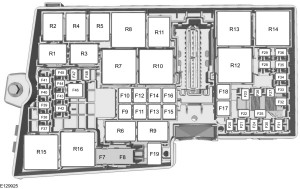
Engine compartment fuse box

Ford Transit 5th generation - fuse box -engine bay (USA version)
Ford Transit 5th generation – fuse box -engine bay (USA version)
Fuse Ampere rating [A] Circuit protected
F1 10 Selective Catalytic Reduction – Diesel
F2 15 Selective Catalytic Reduction – Diesel
F3 15 Selective Catalytic Reduction – Diesel
F4 10 Selective Catalytic Reduction – Diesel
F5 3 Diesel particulate filter vaporizer, glow plug monitor
F6 3 Anti-lock brake system, stability assist, ignition.
F7 7,5 Powertrain control module
F8 20 Cooling fan – Gasoline
F9 30 Left-hand windshield wiper
F10 30 Right-hand windshield wiper
F11 10 Air conditioning clutch
F12 20 Diesel particulate filter vaporizer glow plug
F13 Not used
F14 3 Selective Catalytic Reduction – ignition – Diesel
F15 Not used
F16 Not used
F17 Not used
F18 40 Anti-lock brake system, stability assist pump
F19 30 Starter solenoid
F20 60 Glow plugs
F21 60 Ignition relay 3
F22 40 Selective Catalytic Reduction relay feed
F22 40 Electric vacuum pump relay feed
F23 10 PROTECTED CIRCUIT FUSE
F24 10 Fuel injection pump – Diesel
20 Fuel injection pump – Gasoline
F25 15 Throttle control unit – Diesel.
10 PROTECTED CIRCUIT FUSE – Gasoline
F26 20 PROTECTED CIRCUIT FUSE
F27 Not used
F28 7,5 Crankcase sensor – Diesel.
10 Injection power – Gasoline 3.7L
F29 3 Ignition feed – Audio – Gasoline
7,5 Crank case ventilation heater – Diesel
F30 60 Single cooling fan
40 Twin cooling fan
F31 40 Twin cooling fan 2 – Gasoline
F32 30 Windshield wiper motor
60 Windshield dual wiper motors
F33 20 Start-Stop auxiliary water pump
F34 Not used
F35 20 Powertrain control system supply – Gasoline
15 Powertrain control system supply – Diesel
F36 20 Mass air flow sensor – Gasoline
15 Mass air flow sensor, NOX sensor 1, 2 – Diesel
F37 7,5 Volume Control Valve
F38 20 Air conditioning clutch – Gasoline
7,5 Air conditioning clutch – Diesel


Relay Circuits switched
R1 Ignition 3
R2 Not used
R3 Not used
R4 Not used
R5 Cooling fan – Gasoline
R6 Windshield wiper – on and off
R7 Windshield wiper – low and high speed
R8 Electrical Vacuum Pump – Gasoline
R9 Starter motor
R10 Air conditioning clutch
R11 Fuel vaporizer system glow plug
R12 Fuel injection pump
R13 Not used
R14 Not used
R15 Low and high speed cooling fan
R16 Selective Catalytic Reduction – Diesel
R17 Powertrain control module
R18 High speed cooling fan


Passenger Compartment Fuse Panel

Ford Transit 5th generation - fuse box -passenger compartment (USA version)
Ford Transit 5th generation – fuse box -passenger compartment (USA version)
Fuse Ampere rating [A] Circuits protected
F1 10 Airbag module
F2 4 Anti-lock brake system with electronic stability control, parking brake
F3 Not used
F4 10 Trailer tow back-up lamp relay
F5 20 Cutaway body connectors
F6 Not used
F7 Not used
F8 40 AC power outlet socket
F9 30 Trailer brake module
F10 30 Driver power seat
F11 30 Passenger power seat
F12 30 Trailer tow park lamp relay
F13 25 Anti-lock brake system with electronic stability control valves
F14 5 Powertrain control module B+ relay
F15 40 Powertrain control module power relay
F16 40 Body control module power feed
F17 40 Ignition relay 3
F18 40 Modified vehicle connections
F19 Not used
F20 5 Heated exterior mirror relay
F21 10 Modified vehicle ignition connections
F22 15 Passenger compartment fuse panel
F23 7,5 Air conditioning control module.
F24 10 Cutaway body connectors
F25 7,5 Interior lighting.
F26 10 Heated exterior mirrors
F27 20 Heated rear window
F28 20 Heated rear window
F29 10 Rear parking aid camera, lane keeping system, electro mirror
F30 Not used
F31 10 Trailer brake ignition feed
F32 10 Interior lighting
F33 Not used
F34 Not used
F35 5 Power folding mirrors
F36 20 Horn
F37 7,5 SYNC module0
F38 5 Blower motor, horn relay, windshield wiper relay
F39 7,5 Remote keyless entry, battery, power windows, rear heating, ventilation and air conditioning
F40 40 Front blower motor
F41 40 Rear blower motor
F42 40 Heated rear window
F43 30 Trailer socket
F44 60 Auxiliary power points
F45 40 Trailer connectors B+ supply
F46 30 Power windows
F47 20 Cigar lighter socket
F48 20 Rear auxiliary power points.
F49 20 Front auxiliary power points.
F50 60 Ignition relay 1
F51 60 Ignition relay 2
F52 40 Modified vehicle connections
F53 40 Modified vehicle connections


Relay Circuits switched
R1 Not used (spare)
R2 Auxiliary power points
R3 Trailer tow parking lamp
R4 Ignition 2
R5 Power windows
R6 Ignition 1
R7 Horn
R8 Trailer tow back-up lamp
R9 Front blower motor
R10 Rear blower motor
R11 Heated rear window, heated exterior mirrors
R12 Not used
R13 Modified vehicle connections


Pre-fuse Box

Ford Transit 5th generation - pre fuse box - (USA version)
Ford Transit 5th generation – pre fuse box – (USA version)
Fuse Ampere rating [A] Circuits protected
C 470 Engine compartment fuse box, starter motor, alternator
D 100 Passenger compartment fuse panel, body control module fuse box
E 40 Powertrain control module, anti-lock brake system
F 200 Passenger compartment fuse panel
G 100 Passenger compartment fuse panel
H 80 Positive temperature coefficient heater
J Not used
K 100 Engine junction box feed
L 100 Passenger compartment fuse panel
M 60 Passenger compartment fuse panel supply
N 60 Passenger compartment fuse panel supply
P 60 Auxiliary power point 1
R 60 Auxiliary power point 2
S 60 Auxiliary power point 3


Fuse Fuse ranting Circuits protected
F1 Not used
F2 Not used
F3 Not used
F4 Not used
F5 20 R4 relay power
F6 20 R3 relay power
F7 20 R2 relay power
F8 20 R4 relay power
F9 Not used
F10 Not used
F11 Not used
F12 3 Switch power


Relay Circuit switched
R1 Upfitter 1
R2 Upfitter 2
R3 Upfitter 3
R4 Upfitter 4
R5 Not used
R6 Not used
R7 Not used

Body Control Module

Ford Transit 5th generation - fuse box -control module - (USA version)
Ford Transit 5th generation – fuse box -control module – (USA version)
Fuse Ampere rating [A] Circuits protected
F1 15 Central locking system 2
F2 15 Central locking system 1
F3 15 Ignition switch
F4 5 Parking assist control module, brake transmission shift interlock
F5 5 Rain sensor module
F6 15 Windshield washer pump
F7 Not used
F8 Not used
F9 10 Right-hand high beam
F10 10 Left-hand high beam
F11 25 Right-hand exterior lamps, left-hand position lamps
F12 Not used
F13 15 On-board diagnostic, battery saver
F14 25 Turn signal indicator, power windows delayed accessory, lane departure sensor heated windshield pad
F15 25 Left-hand exterior lamps, right-hand position lamps. High mounted stoplamp
F16 20 Audio unit, navigation unit
F17 7,5 Instrument panel cluster, heater control
F18 10 Headlamp switch module, steering wheel module, stoplamp switch supply
F19 5 Front control/display interface module
F20 5 Ignition passive anti-theft system
F21 3 Accessory relay, customer access feed

WARNING: Terminal and harness assignments for individual connectors will vary depending on vehicle equipment level, model, and market.
Ford Focus Electric – fuse box diagram (USA version)

Ford Focus Electric – fuse box diagram (USA version)


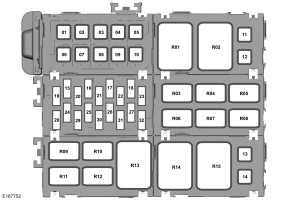
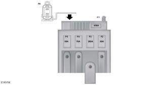
Pre-fuse box

Ford Focus Electric - pre fuse box - USA version
Ford Focus Electric – pre fuse box – USA version


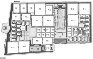
Fuse Ampere rating [A] Circuit protected
F1 80 Electronic power assist steering
F2 150 12 volt battery charge.
F3 100 Power distribution box
F4 50 Body control module (KL30A supply)
F5 70 High voltage battery coolant element one and two
F6 70 Load compartment fuse box.
F7 Not used
F8 50 Electric fan control module.
F9 50 Body control module (KL30B supply)
F10 40 High voltage battery coolant element three.


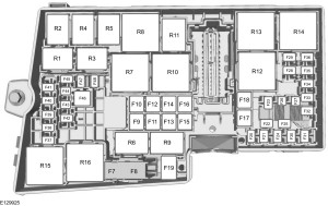
Lift the release lever at the rear of the cover to remove it.


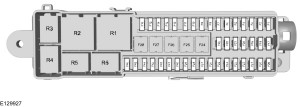
Fuse Ampere rating [A] Circuit protected
F7 40** Anti-lock brake system, stability control (KL30V)
F8 30** Anti-lock brake system, stability control (KL30P)
F9 Not used
F10 40** Blower motor module
F11 40** Brake vacuum pump
F12 40** Electric motor control relay
F13 40** Battery charging control module
F14 40** Coolant heater one.
F15 30** Body control module (KL30C supply)
F16 40** Coolant heater two
F17 Not used
F18 20** Windshield wiper
F19 5* Anti-lock brake system, stability control (KL15)
F20 15* Horn
F21 5* Stop lamp switch
F22 15* Battery monitoring system
F23 5* Relay coils
F24 5* Lighting control switch module
F25 Not used
F26 10* Powertrain control module
F27 15* Charge port light ring
F28 5* Vacuum pump monitor
F29 Not used
F30 5* Transmission control module (12V supply)
F31 10* Smart data link/on-board diagnostic connector
F32 10* Coolant valve, air conditioning solenoid, chiller solenoid
F33 10* Powertrain control module/A/C compressor PSR feedback
F34 15 High voltage battery
F35 Not used
F36 20* Coolant pump
F37 5* Vehicle audible signal for pedestrians
F38 15* Powertrain control module (KL15 supply)
F39 Not used
F40 5* Electronic power assist steering
F41 20* Body control module (KL15 supply)
F42 Not used
F43 15* Daytime running light
F44 Not used
F45 Not used
F46 Not used
F47 Not used
F48 5* Mechanical relay coil fuse.
*Mini fuses**Cartridge fuses


Relay Relay type Circuit switched
R1 Not used.
R2 Micro relay Horn
R3 Not used
R4 Micro relay High voltage battery
R5 Not used
R6 Not used
R7 Power relay Coolant heater element three
R8 Power relay Coolant heater element one and two.
R9 Not used
R10 Mini relay Brake vacuum pump
R11 Not used
R12 Power relay Electronic fan control module
R13 Mini relay Blower motor.
R14 Mini relay Electric motor control
R15 Power relay Brake vacuum pump mechanical relay
R16 Power relay Ignition


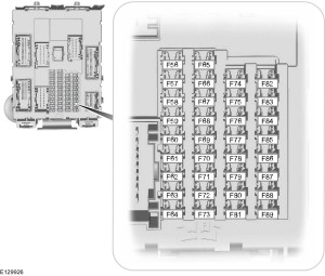
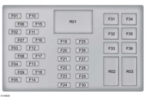
Passenger compartment fuse box

Ford Focus Electric - fuse box - passenger compartment - USA version
Ford Focus Electric – fuse box – passenger compartment – USA version


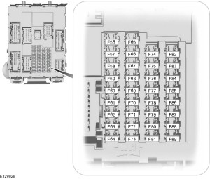
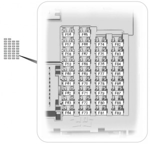
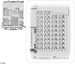
Fuse Ampere rating Circuit protected
F56 Not used
F57 Not used
F58 Not used
F59 Not used
F60 10 Interior lamp, driver door switch pack, glove compartment lamp, ambient lighting lamp
F61 20 Front cigar lighter socket, rear auxiliary power points
F62 Not used
F63 Not used
F64 Not used
F65 10 Luggage compartment lid release
F66 Not used
F67 7,5 Global positioning sensor, SYNC.
F68 Not used
F69 5 Instrument panel cluster
F70 Not used
F71 7,5 Air conditioning
F72 7,5 Steering wheel control module
F73 7,5 Smart data link module
F74 15 High beam headlamp
F75 Not used
F76 10 Reversing lamp
F77 20 Washer pump
F78 5 Ignition switch, push button ignition switch
F79 15 Audio unit, hazard flasher switch, door lock buttons
F80 Not used
F81 5 Radio frequency receiver
F82 20 Washer pump (ground)
F83 20 Central locking (ground)
F84 20 Driver door unlock (ground), double locking ground (ground)
F85 7,5 Heated seats switch
F86 10 Restraint system, passenger airbag deactivation system
F87 Not used
F88 Not used
F89 Not used


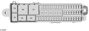
Luggage Compartment Fuse Box

Ford Focus Electric - fuse box - luggage compartment - USA version
Ford Focus Electric – fuse box – luggage compartment – USA version


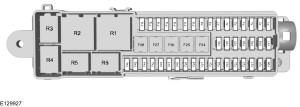
Fuse Ampere rating [A] Circuit protected
F1 5* Cellphone passport module
F2 Not used
F3 5* Keyless vehicle door handles
F4 25* Front power window (left), central locking (front left), power folding mirror (left), heated exterior mirror (left)
F5 25* Front power window (right), central locking (front right), power folding mirror (right), heated exterior mirror (right)
F6 25* Rear left door module (KL30 supply)
F7 25* Rear right door module (KL30 supply)
F8 5* Ignition relay
F9 25* Driver power seat
F10 25* Heated rear window
F11 5* High voltage battery (12V B+)
F12 Not used
F13 Not used
F14 Not used
F15 Not used
F16 Not used
F17 Not used
F18 Not used
F19 Not used
F20 Not used
F21 Not used
F22 Not used
F23 Not used
F24 Not used
F25 Not used
F26 Not used
F27 Not used
F28 Not used
F29 5* High voltage battery (12V B+)
F30 5* Parking aid module
F31 Not used
F32 Not used
F33 15* Rear wiper motor
F34 15* Heated seat (driver)
F35 15* Heated seat (front passenger)
F36 Not used
F37 Not used
F38 Not used
F39 Not used
F40 Not used
F41 Not used
F42 Not used
F43 Not used
F44 Not used
F45 Not used
F46 Not used
*Mini fuses**Cartridge fuses


Relay Relay type Circuit switched
R1 Power relay Rear KL15E.
R2 Mini relay Heated rear window
R3 Micro relay Rear window wiper
R4 Not used
R5 Not used
R5 Not used

WARNING: Terminal and harness assignments for individual connectors will vary depending on vehicle equipment level, model, and market.