Mercedes E class w123 – 280E (1977) – fuse box diagram

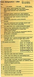
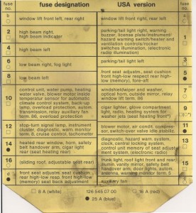
Mercedes w123 – 280E (1977) – USA Version – fuse box diagram

Mercedes w123 (280E) -fuse box
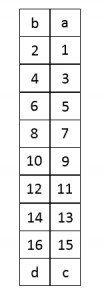
Fuse Ampere rating [A] Colour Description
a 16 red Power windows a front right/rear left
b 16 red Power windows a front left/rear right
c 16 red Auxiliary fan
25 blue Auxiliary heating
d 16 red Sliding roof
1 8 white Parking/tail lights right, license plate/instrument/hazard warning switch/heater and ventilation controls/(rocker switches, shift indicator), illumination, side marker lamps
2 8 white Standing light left and right, clock, trunk light, roof light front and rear, hazard warning system, warning monitor term. SF, (automatic anenna)
3 8 white Parking/tail light left
4 8 white Cigar lighter, glove compartmentlight
16 red Radio, seat heating front
5 8 white Air conditioning compressor switch over valve idle stabilization
6 16 red Windshield wiper and washer, optical horn
7 8 white High beam right, high beam indicator
8 16 red Heated rear window
25 blue Seat heating rear
9 8 white High beam left
10 16 red Blower motor
11 16 red Low beam right, fog light
12 8 white Stop lamp, turn signal lamp, instrument cluster, relay auxiliary fan term. 86, (relay power window term. 86 cruise control)
13 8 white Low beam left
14 8 white Back-up lamp, carburetor heater, idle cut-off valves, emission control, warning monitor term. 15, automatic transmission, horn, (fanfares)


WARNING: Terminal and harness assignments for individual connectors will vary depending on vehicle equipment level, model, and market.

Kia Cerato / Spectra – fuse box diagram

Kia Cerato (Spectra) – fuse box diagram

Kia Cerato - fuse box diagram
Kia Cerato – fuse box diagram

Fuse box in engine compartment

Description Fuse rating [A] Protected component
ATM 20
Automatic transaxle control
ECU1 10
Engine control unit
STOP 15 Stop light
F/WIPER 20 Front wiper
R/FOG 10
Rear fog light
F/FOG 15
Front fog light
LO HDLP 15
Headlight (low)
HI HDLP 15
Headlight (high)
A/CON 10
Air conditioner
F/PUMP 15
Fuel pump
T/OPEN 10
Trunk lid opener
FOLD 10
Outside rearview mirror folding
HORN 10 Horn
DEICE 15 Deicer
INJ 15 Injection
SNSR 10 O2 sensor
ECU2 30
Engine control unit
SPARE 10
spare fuse
SPARE 15
spare fuse
SPARE 20
spare fuse
SPARE 30
spare fuse
ABS2 30
Anti-lock brake system
ABS1 30
Anti-lock brake system
IP B+ 50
In panel B+
BLOWER 30
Blower
IGN2 30
Ignition
IGN1 30
Ignition
RAD 30
Radiator fan
COND 20
Condenser fan
ALT 120 Alternater (petrol)
140 Alternater (diesel)
ATM Automatic transaxle control relay
WIPER
Wiper relay
F/FOG
Front fog light relay
LO HDLP
Headlight relay (low) 
HI HDLP
Headlight relay (high)
A/CON
Air conditioner relay
F/PUMP
Fuel pump
DRL
Daytime running light relay
COND2
Condenser fan relay
HORN
Horn relay
MAIN
Main relay
START
Start motor relay
RAD
Radiator fan relay
COND
Condenser fan relay


Fuse box – driver-side knee bolster

Description Fuse rating [A] Protected component
START 10
Start motor
SRF/D_LOCK 20
Sunroof, Door lock
RR FOG 10
Hazard warning flasher
HAZARD 10
Hazard warning flasher
A/CON 10
Air conditioner
CLUSTER 10
Cluster
RKE 10
Remote keyless entry
S/HTR 20
Seat warmer
C/LIGHTER 15
Cigar lighter
A/BAG 15
Air bag
R/WIPER 15
Rear wiper
AUDIO 10 Audio
ABS 10
Anti-lock brake system
ACC/PWR 15
Accessory / Power socket
ROOM 15
Room lamp
IGN 10
Ignition
ECU 10
Engine control unit
TAIL RH 10
Tail light (right)
T/SIG 10
Turn signal light
RR/HTR 30
Rear window defroster
P/WDW LH 25
Power window (left)
HTD/MIRR 10
Outside rearview mirror heater 
P/WDW RH 25
Power window (right)
TAIL LH 10
Tail light (left)
RR/HTR
Rear window defroster relay
RESISTOR
Resistor
P/WDW
Power window relay
ACC/PWR
Accessory / Power socket relay
TAIL
Tail light relay

WARNING: Terminal and harness assignments for individual connectors will vary depending on vehicle equipment level, model, and market.
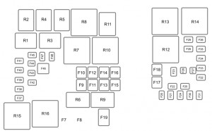
Ford Fiesta (1995 – 1999) – fuse box diagram

Ford Fiesta (1995 – 1999) – fuse box diagram

Year of production: 1995, 1996, 1997, 1998, 1999

Central fusebox in passenger compartment

Ford Fiesta mk4 fuse box - passenger compartment
Ford Fiesta mk4 fuse box – passenger compartment


Fuse Ampere rating [A] Circuit protected
F1 15 Cigar lighter
F2 20 Interior lights, clock, radio memory
F3 Not used
F4 15 Heated rear sensor/exterior mirrors
F5 20 Horn, alarm
F6 10 LH sidelights
F7 10 RH sidelight
F8 15 Central locking, electric mirrors
F9 15 Seat hight adjustment
F10 15 Heated front seats
F11 30 Central locking, electric windows
F12 20 Wiper motor, screen washer pump
F13 15 Brake light, instrument panel
F14 10 Air bag
F15 10 Heated mirror
F16 30 Heater blower motor
F17 15 Direction indicators
F18 15 Ignition
F19 10 Engine management, alarm, radio
F20 30/10 Head washer (Skandinavia only),  Dim/dip (RHD only)
F21 Not used
F22 10 Diagnostic plug
F41 10 Rear fog light (depending on country)
F42 10 Rear fog light (depending on country)
F43 10 Daytime running lights (Scandinavia only). High beam locking diode (RHD only)
F44 20 Door locking module
F45 15 Luggage compartment release (central locking only)

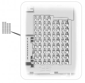
 Auxiliary fusebox in engine bay

Ford-fiesta-mk4-fuse-box-engine-bay


Fuse Ampere rating [A] Circuit protected
F1 Protection diode for EEC V relay
F2 Not used
F3 Not used
F23 10 LH main beam
F24 10 PH main beam
F25 10 LH low beam
F26 10 RH low beam
F27 10 Lambda sensor (petrol)
15 Fuel heater (diesel)
F28 15 Engine management
F29 20 Reversing lights/compressor cluch (a/c)
F30 3 ABS module
F31 30 ABS module
F32 3 EEC Vignition module
F33 30 ABS module
F34 25 Transmission
F35 10 Fuel pump (petrol)
3 PATS module (diesel engine)
F36 60 Engine management, blowe, fuel pump, glow plug (diesel)
F37 40 Heated windscreen
F38 60 Central locking, heated rear screen
F39 60 Headlight washer
F40 60 Ignition lock

WARNING: Terminal and harness assignments for individual connectors will vary depending on vehicle equipment level, model, and market.
Volkswagen Golf mk5 – fuse box diagram

VW Golf mk5  – fuse box

Fuse box in passenger compartment

Volkswagen Golf 5 – fuse box passenger compartment
Fuse Ampere rating [A] Protected circuit
1 10 Data Link Connector (DLC)
2 10 Ani-lock breake system (ABS)
3 10 Power steering
4 5 Heated seats, heater/air conditioning (A/C)
5 5 Breake pedal position (BPP) switch, clutch position potentiometr
6 5 Databus connection, engine management, instrumention control module
7 5 Headlamp level control module
8 5 Interrior rear view mirror
9 5 Four wheel drive control module
10 5 Telephone
11 5 Trailer control module
12 10 Door function control module, driver, passenger
13 10 Data Link Connector (DLC), light switch
14 10 Breake pedal position (BPP) switch
15 7,5 Multifunction control module 1
16 10 Heater/air conditioning (A/C)
17 5 Audio system, windscreen wiper rain sensor
18 30 Parking aid control module
19 Not used
20 5 Ani-lock breake system (ABS) – Taves Mk60
21 Not used
22 40 Heater/air conditioning (A/C)
23 30 Electric windows
24 20 Cigarette lighter
25 25 Multifunction control module 1
26 30 Charging socket
27 15 Engine management
28 Not used
29 10 Engine management
30 5 Airbag
31 5 Reversing lamp
32 30 Electric windows
33 25 Sunroof
34 15 Electric seats
35 5 Alarm system
36 20 Headlamp washers
37 30 Heated seats
38 Not used
39 Not used
40 40 Heater/air conditioning (A/C)
41 20 Rear screen wash/wipe system
42 20 Windscreen washers
43 15 Trailer control module
44 20 Trailer control module
45 15 Trailer control module
46 5 Heater/air conditioning (A/C), windscreen washers jet heaters
47 5 Heater/air conditioning (A/C)
48 7,5 Electric seats, steering column adjustment
49 5 Light switch


Fuse box in engine compartment

Volkswagen Golf mk5 - fuse box engine compartment
Volkswagen Golf mk5 – fuse box engine compartment
Fuse Ampere rating [A] Protected cirucuit
F1 30 Ani-lock breake system (ABS)
F2 30 Ani-lock breake system (ABS)
F3 20 Multifunction control module 2
F4 5 Multifunction control module 2
F5 20 Horn
F6 20 Engine management
F7 5 Breake pedal position (BPP) switch, clutch position potentiometr
F8 10 Engine coolant blower motor control module, engine management
F9 10 Engine management
F10 10 Engine management
F11 25 Engine management – petrol
30 Engine management – diesel
F12 15 Engine management
F13 20 Automatic transmission (AT)
F14 Not used
F15 40 Starter motor
F16 15 Steering column function control module
F17 10 Instrument panel
F18 Not used
F19 15 Audio system, navigation system
F20 10 Telephone
F21 Not used
F22 Not used
F23 10 Cruise control
F24 10 Databus connection
F25 Not used
F26 5 Engine management – diesel
10 Engine management – petrol
F27 10 Cranckcase breather heater
F28 20 Automatic transmission (AT)
F29 20 Engine management
F30 20 Heater/air conditioning (A/C)
F31 25 Windscreen wipers
F32 10 Engine management
F33 15 Fuel lift pump
F34 Not used
F35 Not used
F36 Not used
F37 Not used
F38 10 Headlamps adjustment
F39 5 Engine oil temperature sensor, instrument panel
F40 20 Fascia fuse box /relay plate (F1 – F11/F29 – F31)
F41 Not used
F42 5 Engine management – petrol
10 Engine management – diesel
F43 Not used
F44 Not used
F45 Not used
F46 Not used
F47 40 Multifunction control module 1
F48 40 Multifunction control module 1
F49 Not used
F50 40 Audio system
F51 50 Glow plug control module
F52 50 Multifunction control module 1
F53 50 Fascia fuse box /relay plate 1 (F32 – F37), fascia fuse box /relay plate 2 (F4)
F54 Not used

Relays

Relays Description
1 Ignition main circuits relay 2
2 Starter motor relay
3 Fuel pump relay – 1,4 (BCA)/1,6 (BGU)
4 Ignition main circuits relay 1


WARNING: Terminal and harness assignments for individual connectors will vary depending on vehicle equipment level, model, and market.

Volkswagen Golf mk3 – fuse box diagram

VW Golf mk3 – fuse box

Volkswagen Golf mk3 – fuse box
Volkswagen Golf mk3 - separate relays above fuse/relay panel
Volkswagen Golf mk3 – separate relays above fuse/relay panel

Fuse arrangement according to the numbers on fuse panel from left to right)

Fuse Ampere rating  [A] Circuits protected
1 10 Headlight, low beam, left
2 10 Headlight, low beam, right
3 10 Instrument panel lights, license plate lights
4 15 Rear window wiper (wagon)
5 15 Windshield wiper/washer
6 20 Fresh air fan
7 10 Side marker and taillights, right
8 10 Side marker and taillights, left
9 20 Rear window defogger
10 Open
11 10 Headlight, high beam, left
12 10 Headlight, high beam, right
13 10 Horn
14 15 Back-up lights, heated windshield washer nozzles
15 10 Deceleration fuel cut-off, fuel pump after run
16 15 Instrument cluster lights, glove compartment light
17 10 Emergency flashers
18 20 Fuel pump, oxygen sensor heater
19 30 Radiator cooling fan, A/C relay
20 10 Brake lights
21 15 Interior lights, cigarette lighter, digital clock
22 10 Radio

Relay location on fuse/relay panel

R1 A/C relay
R2 Rear window wiper (wagon)
R3 Open
R4 Load reduction relay
R5 Low coolant level control unit
R6 Emergency flasher relay
R7 Open
R8 Intermittent wash wipe relay
R9 Seat belt warning system control unit
R10 Open
R11 Horn relay
R12 Fuel pump relay
Separate relays above fuse/relay panel
R13 Back-up light fuse (auto. trans.)
R14 Radiator cooling fan after run control unit
R15 ABS hydraulic pump relay
R16 ABS relay
R17 Open
R18 Open
R19 A/C relay
R20 Starter cut-outback-up light relay
R21 ABS hydraulic pump fuse/power window fuse
R22 ABS valves fuse
R23 Cruise control fuse/automatic shoulder belt system fuse
R24 Open

Connections and plugs on fuse/relay panel

Volkswagen Vento - fuse box (connections and plugs)
Volkswagen Vento – fuse box (connections and plugs)
Symbol Description
A1 Headlight wiring harness (yellow)
A2 Headlight wiring harness (yellow)
B Open
C Headlight wiring harness (yellow)
D Optional equipment wiring harness (green)
E Instrument wiring harness (green)
F Engine compartment wiring harness, right (white)
G1 Engine compartment wiring harness, right (white)
G2 Engine compartment wiring harness, right (white)
H1 Steering column switch wiring harness (red)
H2 Steering column switch wiring harness (red)
J Steering column switch wiring harness (red)
K Rear wiring harness (black)
L Rear wiring harness (black)
M Rear wiring harness (black)
N A/C wiring harness (green)
P Rear window defroster wiring harness (blue)
Q Instrument wiring harness (blue)
R Light switch wiring harness (blue)
S Engine compartment wiring harness, right (white)
T Two-point connector (green)
U1 Instrument cluster wiring harness (blue)
U2 Instrument cluster wiring harness (blue)
V Multi-function indicator wiring hamess (green)
W Six-point connector (green)
X Warning lamp wiring harness (green)
Y Single connector, terminal 30
Z1 Single connector
Z2 Single connector, terminal 31
30 Single connector, terminal 30
30B Single connector
31 Single connector, terminal 31

WARNING: Terminal and harness assignments for individual connectors will vary depending on vehicle equipment level, model, and market.

Volkswagen Vento – fuse box diagram

VW Vento – fuse box

Volkswagen Vento fuse box
Volkswagen Vento - separate relays above fuse/relay panel
Volkswagen Vento – separate relays above fuse/relay panel

Fuse arrangement according to the numbers on fuse panel from left to right)

Fuse Ampere rating  [A] Circuits protected
1 10 Headlight, low beam, left
2 10 Headlight, low beam, right
3 10 Instrument panel lights, license plate lights
4 15 Rear window wiper (wagon)
5 15 Windshield wiper/washer
6 20 Fresh air fan
7 10 Side marker and taillights, right
8 10 Side marker and taillights, left
9 20 Rear window defogger
10 Open
11 10 Headlight, high beam, left
12 10 Headlight, high beam, right
13 10 Horn
14 15 Back-up lights, heated windshield washer nozzles
15 10 Deceleration fuel cut-off, fuel pump after run
16 15 Instrument cluster lights, glove compartment light
17 10 Emergency flashers
18 20 Fuel pump, oxygen sensor heater
19 30 Radiator cooling fan, A/C relay
20 10 Brake lights
21 15 Interior lights, cigarette lighter, digital clock
22 10 Radio

Relay location on fuse/relay panel

R1 A/C relay
R2 Rear window wiper (wagon)
R3 Open
R4 Load reduction relay
R5 Low coolant level control unit
R6 Emergency flasher relay
R7 Open
R8 Intermittent wash wipe relay
R9 Seat belt warning system control unit
R10 Open
R11 Horn relay
R12 Fuel pump relay
Separate relays above fuse/relay panel
R13 Back-up light fuse (auto. trans.)
R14 Radiator cooling fan after run control unit
R15 ABS hydraulic pump relay
R16 ABS relay
R17 Open
R18 Open
R19 A/C relay
R20 Starter cut-outback-up light relay
R21 ABS hydraulic pump fuse/power window fuse
R22 ABS valves fuse
R23 Cruise control fuse/automatic shoulder belt system fuse
R24 Open

Connections and plugs on fuse/relay panel

Volkswagen Vento - fuse box (connections and plugs)
Volkswagen Vento – fuse box (connections and plugs)
Symbol Description
A1 Headlight wiring harness (yellow)
A2 Headlight wiring harness (yellow)
B Open
C Headlight wiring harness (yellow)
D Optional equipment wiring harness (green)
E Instrument wiring harness (green)
F Engine compartment wiring harness, right (white)
G1 Engine compartment wiring harness, right (white)
G2 Engine compartment wiring harness, right (white)
H1 Steering column switch wiring harness (red)
H2 Steering column switch wiring harness (red)
J Steering column switch wiring harness (red)
K Rear wiring harness (black)
L Rear wiring harness (black)
M Rear wiring harness (black)
N A/C wiring harness (green)
P Rear window defroster wiring harness (blue)
Q Instrument wiring harness (blue)
R Light switch wiring harness (blue)
S Engine compartment wiring harness, right (white)
T Two-point connector (green)
U1 Instrument cluster wiring harness (blue)
U2 Instrument cluster wiring harness (blue)
V Multi-function indicator wiring hamess (green)
W Six-point connector (green)
X Warning lamp wiring harness (green)
Y Single connector, terminal 30
Z1 Single connector
Z2 Single connector, terminal 31
30 Single connector, terminal 30
30B Single connector
31 Single connector, terminal 31

WARNING: Terminal and harness assignments for individual connectors will vary depending on vehicle equipment level, model, and market.

Volkswagen Passat B4 (1993 – 1996) – fuse box diagram

VW Passat B4 (1993 – 1996) – fuse box diagram

Year of production: 1993, 1994, 1995, 1996

Fuse box

Volkswagen Passat B4 – fuse box


Volkswagen Passat B3 - separate relays above fuse/relay panel
Volkswagen Passat B4 – separate relays above fuse/relay panel

Fuse arrangement according to the numbers on fuse panel from left to right)

Fuse Ampere rating  [A] Circuits protected
1 10 Headlight, low beam, left
2 10 Headlight, low beam, right
3 10 Instrument panel lights, license plate lights
4 15 Rear window wiper (wagon)
5 15 Windshield wiper/washer
6 20 Fresh air fan
7 10 Side marker and taillights, right
8 10 Side marker and taillights, left
9 20 Rear window defogger
10 Open
11 10 Headlight, high beam, left
12 10 Headlight, high beam, right
13 10 Horn
14 15 Back-up lights, heated windshield washer nozzles
15 10 Deceleration fuel cut-off, fuel pump after run
16 15 Instrument cluster lights, glove compartment light
17 10 Emergency flashers
18 20 Fuel pump, oxygen sensor heater
19 30 Radiator cooling fan, A/C relay
20 10 Brake lights
21 15 Interior lights, cigarette lighter, digital clock
22 10 Radio

Relay location on fuse/relay panel

R1 A/C relay
R2 Rear window wiper (wagon)
R3 Open
R4 Load reduction relay
R5 Low coolant level control unit
R6 Emergency flasher relay
R7 Open
R8 Intermittent wash wipe relay
R9 Seat belt warning system control unit
R10 Open
R11 Horn relay
R12 Fuel pump relay
Separate relays above fuse/relay panel
R13 Back-up light fuse (auto. trans.)
R14 Radiator cooling fan after run control unit
R15 ABS hydraulic pump relay
R16 ABS relay
R17 Open
R18 Open
R19 A/C relay
R20 Starter cut-outback-up light relay
R21 ABS hydraulic pump fuse/power window fuse
R22 ABS valves fuse
R23 Cruise control fuse/automatic shoulder belt system fuse
R24 Open

Connections and plugs on fuse/relay panel

Volkswagen Passat B3 - fuse box (connections and plugs)
Volkswagen Passat B4 – fuse box (connections and plugs)
Symbol Description
A1 Headlight wiring harness (yellow)
A2 Headlight wiring harness (yellow)
B Open
C Headlight wiring harness (yellow)
D Optional equipment wiring harness (green)
E Instrument wiring harness (green)
F Engine compartment wiring harness, right (white)
G1 Engine compartment wiring harness, right (white)
G2 Engine compartment wiring harness, right (white)
H1 Steering column switch wiring harness (red)
H2 Steering column switch wiring harness (red)
J Steering column switch wiring harness (red)
K Rear wiring harness (black)
L Rear wiring harness (black)
M Rear wiring harness (black)
N A/C wiring harness (green)
P Rear window defroster wiring harness (blue)
Q Instrument wiring harness (blue)
R Light switch wiring harness (blue)
S Engine compartment wiring harness, right (white)
T Two-point connector (green)
U1 Instrument cluster wiring harness (blue)
U2 Instrument cluster wiring harness (blue)
V Multi-function indicator wiring hamess (green)
W Six-point connector (green)
X Warning lamp wiring harness (green)
Y Single connector, terminal 30
Z1 Single connector
Z2 Single connector, terminal 31
30 Single connector, terminal 30
30B Single connector
31 Single connector, terminal 31

WARNING: Terminal and harness assignments for individual connectors will vary depending on vehicle equipment level, model, and market.

Volkswagen Golf 2 CE2 (from 1989) – fuse box

VW Golf 2 CE2 (from 1989) – fuse box

CE2 Fusebox Fuses & Relays

Volkswagen Golf mk2 CE2 - fuse box
Volkswagen Golf mk2 CE2 – fuse box

Fuse Ampere rating [A] Description
1 10 Headlight, low beam, left
2 10 Headlight, low beam, right
3 10 Instrument panel lights, license plate lights
4 15 Glove compartment light, rear wiper
5 15 Wiper/washer
6 20 Fresh air blower, Air conditioning
7 10 Rear light, sidelight, right
8 10 Rear light, sidelight, left
9 20 Rear window defogger
10 15 Fog lights
11 10 Headlight, high beam, left, High beam indicator light
12 10 Headlight, high beam, right
13 10 Horn, Radiator cooling fan after run relay
14 15 Reverse lights, heated washer jets
15 10 Engine electronics, stabilizer valve, cold start valve
16 15 Instrument panel warning lights, MFA
17 10 Hazard switch, indicators
18 20 Fuel pump, oxygen sensor heater
19 30 Radiator cooling fan, air conditioning
20 10 Brake lights, cruise control
21 15 Interior lights, dash clocks, boot light, central locking
22 10 Radio, cigarette lighter


Relay Desciption
1 Air conditioning
2 Rear Wiper
3 ECU relay
4 Load reduction/x-over relay
5 Low coolant level control unit or Open
6 Emergency flashers
7 Headlight washers
8 Intermittent wipers
9 Seat belt/lights on warning relay
10 Fog lights
11 Horn
12 Fuel pump (fuel injection) Glow plugs (diesel)
13 Radiator cooling fan after run (except 16-valve) 2.0 16-valve: Starter interlock relay
14 Automatic gearbox, coolant temperature indicator, starter interlock relay (except 2.0 16-valve) 2.0 16-valve: Radiator cooling fan after run
15 ABS pump relay
16 ABS relay
17 Heated seat control unit, driver
18 Heated seat control unit, passenger, or Electric seat circuit breaker
19 Automatic gearbox
20 Open
21 Electric window relay, ABS hydraulic pump fuse
22 ABS valves fuse
23 Air conditioning, power seat fuse
24 Electric window fuse

CE2 Fusebox – Rear Connections

Volkswagen Golf mk2 CE2 - fuse box - rear connection
Volkswagen Golf mk2 CE2 – fuse box – rear connection
A1 Yellow 8 pin Headlight wiring harness
A2 Yellow 8 pin Headlight wiring harness
B Green 6 pin Headlight washer wiring harness
C Yellow 8 pin Headlight or wiper motor wiring harness
D Green 12 pin Miscellaneous equipment, varies (A/C, A/T, heated seats, seat belt warning, etc.)
E Green 5 pin Instrument or brake light wiring harness
F White 10 pin Engine compartment/engine management, wiring harness, right side (position 10 open)
G1 White 12 pin Engine compartment/engine management, right side
G2 White 12 pin Engine compartment/engine management, right side (position 12 open)
H1 Red 10 pin Steering column switch wiring harness
H2 Red 8 pin Steering column switch wiring harness (position 8 open)
J Red 10 pin Steering column switch wiring harness
K Black 12 pin Rear wiring harness
L Black 8 pin Rear/Parking brake wiring harness (position 8 open)
M Black 6 pin Rear/fuel tank wiring harness
N Green 6 pin Air conditioning wiring harness
P Blue 10 pin Rear window defroster/fog light wiring harness
Q Blue 6 pin Fresh air blower fan wiring harness (position 10 open)
R Blue 10 pin Light switch wiring harness
S White 5 pin Engine compartment/wiper motor wiring harness, right side
T Green 2 pin Individual circuits
U1 Blue 14 pin Instrument cluster wiring harness
U2 Blue 14 pin Instrument cluster wiring harness
V Green 4 pin Steering column switch Multi-function indicator wiring harness
W Green 6 pin Miscellaneous optional equipment, varies with vehicle type
X Green 8 pin Warning lamp wiring harness
Y 1 pin 4 single point connectors for terminal 30 circuit (some may be bridged with red connector)
Z1 1 pin Single point connector
Z2 1 pin Single point connector for terminal 31 circuit
30 1 pin Single point connector for terminal 30 circuit (may be bridged to 30B with red connector)
30B 1 pin Single point connector (may be bridged to 30 with red connector)

WARNING: Terminal and harness assignments for individual connectors will vary depending on vehicle equipment level, model, and market.

Volkswagen Passat B3 (1988 – 1993) – fuse box diagram

VW Passat B3 – fuse box diagram

Year of productions: 1988, 1989, 1990, 1991, 1992, 1993

Fuse box

Volkswagen Passat B3 – fuse box


Volkswagen Passat B3 - separate relays above fuse/relay panel
Volkswagen Passat B3 – separate relays above fuse/relay panel

Fuse arrangement according to the numbers on fuse panel from left to right)

Fuse Ampere rating  [A] Circuits protected
1 10 Headlight, low beam, left
2 10 Headlight, low beam, right
3 10 Instrument panel lights, license plate lights
4 15 Rear window wiper (wagon)
5 15 Windshield wiper/washer
6 20 Fresh air fan
7 10 Side marker and taillights, right
8 10 Side marker and taillights, left
9 20 Rear window defogger
10 Open
11 10 Headlight, high beam, left
12 10 Headlight, high beam, right
13 10 Horn
14 15 Back-up lights, heated windshield washer nozzles
15 10 Deceleration fuel cut-off, fuel pump after run
16 15 Instrument cluster lights, glove compartment light
17 10 Emergency flashers
18 20 Fuel pump, oxygen sensor heater
19 30 Radiator cooling fan, A/C relay
20 10 Brake lights
21 15 Interior lights, cigarette lighter, digital clock
22 10 Radio

Relay location on fuse/relay panel

R1 A/C relay
R2 Rear window wiper (wagon)
R3 Open
R4 Load reduction relay
R5 Low coolant level control unit
R6 Emergency flasher relay
R7 Open
R8 Intermittent wash wipe relay
R9 Seat belt warning system control unit
R10 Open
R11 Horn relay
R12 Fuel pump relay
Separate relays above fuse/relay panel
R13 Back-up light fuse (auto. trans.)
R14 Radiator cooling fan after run control unit
R15 ABS hydraulic pump relay
R16 ABS relay
R17 Open
R18 Open
R19 A/C relay
R20 Starter cut-outback-up light relay
R21 ABS hydraulic pump fuse/power window fuse
R22 ABS valves fuse
R23 Cruise control fuse/automatic shoulder belt system fuse
R24 Open

Connections and plugs on fuse/relay panel

Volkswagen Passat B3 - fuse box (connections and plugs)
Volkswagen Passat B3 – fuse box (connections and plugs)
Symbol Description
A1 Headlight wiring harness (yellow)
A2 Headlight wiring harness (yellow)
B Open
C Headlight wiring harness (yellow)
D Optional equipment wiring harness (green)
E Instrument wiring harness (green)
F Engine compartment wiring harness, right (white)
G1 Engine compartment wiring harness, right (white)
G2 Engine compartment wiring harness, right (white)
H1 Steering column switch wiring harness (red)
H2 Steering column switch wiring harness (red)
J Steering column switch wiring harness (red)
K Rear wiring harness (black)
L Rear wiring harness (black)
M Rear wiring harness (black)
N A/C wiring harness (green)
P Rear window defroster wiring harness (blue)
Q Instrument wiring harness (blue)
R Light switch wiring harness (blue)
S Engine compartment wiring harness, right (white)
T Two-point connector (green)
U1 Instrument cluster wiring harness (blue)
U2 Instrument cluster wiring harness (blue)
V Multi-function indicator wiring hamess (green)
W Six-point connector (green)
X Warning lamp wiring harness (green)
Y Single connector, terminal 30
Z1 Single connector
Z2 Single connector, terminal 31
30 Single connector, terminal 30
30B Single connector
31 Single connector, terminal 31

WARNING: Terminal and harness assignments for individual connectors will vary depending on vehicle equipment level, model, and market.

Volkswagen Jetta mk2 – fuse box diagram

VW Jetta mk2 – fuse box

Volkswagen Jetta mk2 – fuse box

Fuses/relays panel

Fuse Ampere rating  [A] Protected circuit
1 10 Headlight, Low Beam, Left
2 10 Headlight, Low Beam, Right
3 10 License plate lights
4 15 Rear Window Wiper And Washer System
5 15 Windshield Wiper/Washer
6 20 Fresh Air Blower, A/C
7 10 Tail Lights, Right
8 10 Tail Lights, Left
9 20 Rear Window Defogger
10 15 Fog Lights
11 10 Headlight, High Beam, Left
12 10 Headlight, High Beam, Right
13 10 Horn
14 15 Back-Up Lights
15 10 Engine Electronics
16 15 Power Sunroof, Front Map/Reading Light
10 Emergency Flashers
18 20 Fuel Pump (FP), Heated Oxygen Sensor Control Module
19 30 Coolant Fan, A/C Relay
20 10 Brake Lights
21 15 Interior Lights, Clock, Luggage Compartment light
22 10 Cigarette Lighter, Radio, Luggage Compartment Release

Connections and plugs on rear of fuse/relay panel

Volkswagen Corrado - connections and plugs on fuse/relay panel
Volkswagen Corrado – connections and plugs on fuse/relay panel
A1 Yellow 8 pin Headlight wiring harness
A2 Yellow 8 pin Headlight wiring harness
B Green 6 pin Headlight washer wiring harness
C Yellow 8 pin Headlight or wiper motor wiring harness
D Green 12 pin Miscellaneous equipment, varies (A/C, A/T, heated seats, seats belt warning, etc.)
E Green 5 pin Instrument or brake light wiring harness
F White 10 pin Engine compartment/engine management, wiring harness, right side (position 10 open)
G1 White 12 pin Engine compartment/engine management, right side
G2 White 12 pin Engine compartment/engine management, right side (position 12 open)
H1 Red 10 pin Steering column switch wiring harness
H2 Red 8 pin Steering column switch wiring harness (position 8 open)
J Red 10 pin Steering column switch wiring harness
K Black 12 pin Rear wiring harness
L Black 8 pin Rear/Parking brake wiring harness (position 8 open)
M Black 6 pin Rear/fuel tank wiring harness
N Green 6 pin Air conditioning wiring harness
P Blue 10 pin Rear window defroster/fog light wiring harness
Q Blue 6 pin Fresh air blower fan wiring harness (position 10 open)
R Blue 10 pin Light switch wiring harness
S White 5 pin Engine compartment/wiper motor wiring harness, right side
T Green 2 pin Individual circuits
U1 Blue 14 pin Instrument cluster wiring harness
U2 Blue 14 pin Instrument cluster wiring harness
V Green 4 pin Steering column switch Multi-function indicator wiring harness
W Green 6 pin Miscellaneous optional equipment, varies with vehicle type
X Green 8 pin Warning lamp wiring harness
Y n/a 1 pin 4 single point connectors for terminal 30 circuit (some may be bridged with red connector)
Z1 n/a 1 pin Single point connector
Z2 n/a 1 pin Single point connector for terminal 31 circuit
30 n/a 1 pin Single point connector for terminal circuit (may be bridged to 30B with red connector)
30B n/a 1 pin Single point connector for terminal 30 circuit (may be bridged to 30 with red connector)

WARNING: Terminal and harness assignments for individual connectors will vary depending on vehicle equipment level, model, and market.