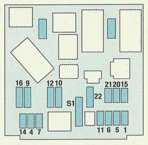
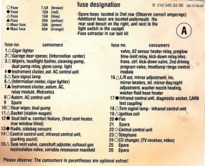
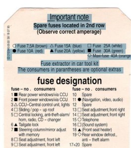
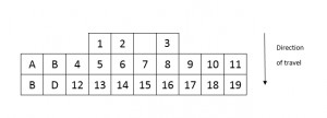
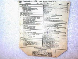
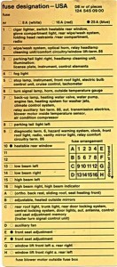
Mercedes C Class w204 (2008 – 2014) – fuse box diagram

Mercedes Benz C Class w204 (Third Generation 2008-2014) – fuse box diagram

Year of production: 2008, 2009, 2010, 2011, 2012, 2013, 2014

Model: C180, C200, C250, C280, C300, C350, C63, AMG

Fuse box table

Description Fuse number
A/C System Heater 12
ABS/ASR/BAS/ESP 1,6,13,14,16,20,21
AC in rear Compartment 119
Adaptive Damping System 12,17
Airbag system 8,15,37,77
Ambient Lighting 2,3,39,41
Antenna Module 46
Anti Thef Alarm 46
Auto Dimming Rear View Mirror 17
Automatic Transmission 16,33
Brake lights 21
CD Charger 43
Ceiling Lamps 17
Central Display 11
Central Locking 2,3
 Cigar lighter 71
COMAND 26
Control Unit Height adjustment 69
Cortesy Lights/Warnings lamps 2,3,39,41
Diagnostic socket 16
Engine electronics 6,19,22,23,24,25,27,32,75
Exterior Lamp Switch 18
Exterior Mirror Function 2,3
Fanfare Horn 13,31a,31b
Fuel pump 4,6,19,23,27,42
Garage Door Opener 17
Glove compartment light 21
Hazard warning flashers 18
Headlamp flasher 13
Headlamp range adjustment 29,30
Heated rear window 49
Ignition lock 19,27
Instrument cluster 5,28
Interior motion sensor 46
KEYLESS-GO 74
Make-up mirror lamp 17
Mobile phone 21
Multi-contour seats 60
Multi-function steering wheel 13
NECK-PRO 37
Panoramic glass roof 17
PARKTRONIK system 12,59
Power window, front 2,3
Power window, rear 39,41
PRESAFE safety system 50,51
Radio system 26,84
Rain sensor 17
Reading lamps 17
Rear compartment 86
Rearwindow sunstade 12
Rear windscreen wash system 38
Remote tailgate closing 61
Satellite radio 26,84
Seat adjustment, front 2,3,44,45,116,126
Seat heating, driver 12
Seat heating, front passenger 12
Socket front 9,71,78
Socket, lead compartment 72
Socket, rear 76
Sound system 67
Starter 6,7,19,27
Steering lock 19,27
Steering wheel adjustment 2,116
Switch illumination 2,3,12,17,39,41
TELE AID 83,87
Tilting/Sliding sunroof 17
Tire pressure monitoring system 70
Tow-away protection 46
Trailer brake 53
Trailer hitching 53,54,56,57,58
Turn signal lamp 13
TV Tuner 85
Windshield washer lamp 13
Windshield wiperd, rear 13
Windshield wipers, front 10,13

Fuse rating

 Fuse number Ampere Colour
16,59,70,77 5 Beige
4,5,8,11,12,13,14,15,18,21,27,28,46,54,60,83,84,85,87,119 7,5 Brown
6,29,30,33 10 Red
9,22,24,25,31,38,56,71,72,74,76,117 15 Blue
7,19,23,26,42,57,75 20 Yellow
1 25 White
2,3,10,17,44,45,53,58,116,126 30 Green
20,32,49,61,67 40 Amber
50,51 50 Red

Mercedes Class C w204 – fuse box engine compartment

Mercedes Class C w204 – fuse box engine compartment

Mercedes Class C w204 – fuse box – luggage compartment


Mercedes Class C w204 – fuse box – luggage compartment


Mercedes Class C w204 – fuse box – passenger compartment


Mercedes Class C w204 – fuse box – passenger compartment

WARNING: Terminal and harness assignments for individual connectors will vary depending on vehicle equipment level, model, and market.

Ford Mustang (2003 – 2012) – fuse box diagram

Ford Mustang (2003 – 2012) – fuse box diagram

Year of production: 2003, 2004, 2005, 2006, 2007, 2008, 2009, 2010, 2011, 2012

Passenger junction box

Ford Mustang V – fuse box – passenger junction


Fuse Ampere rating [A] Description
1 20 Cigar lighter
2 20 Engine controls
3 Not used
4 10 Right-hand low beam headlamp
5 15 Instrument cluster, Traction control switch
6 20 Starter motor relay
7 15 GEM, Interior lamps
8 20 Engine controls
9 30 Mach 460 subwoofers
10 10 Left-hand low beam headlamp
11 15 Back-up lamps
12 2 Heated PCV
13 15 Electronic flasher
14 Not used
15 15 Power lumbar
16 Not used
17 15 Speed control servo, Shift lock actuator
18 15 Electronic flasher
19 15 Power mirror switch, GEM, Anti-theft relay, Power door locks, Door ajar switches
20 15 Convertible top switch
21 5 Instrument cluster and engine control memory
22 Not used
23 15 A/C clutch, Defogger switch
24 30 Climate control blower motor
25 25 Luggage compartment lid release
26 30 Wiper/Washer motor, Wiper relays
27 20 Radio
28 15 GEM, Overdrive cancel switch
29 15 Anti-lock Brake System (ABS) module
30 15 Daytime Running Lamps (DRL) module
31 10 Data link connector
32 15 Radio, GEM
33 15 Stop lamp switch, Speed control deactivation switch
34 20 Instrument Cluster, CCRM, Data link connector, Securilock transceiver module
35 15 Shift lock actuator, Powertrain Control Module (PCM), Speed control servo, ABS module
36 15 Air bag control module
37 5 Adjustable illumination
38 20 High beams
39 5 GEM
40 Not used
41 15 Brake lamp
42 Not used
43 20 CB Power windows
44 Not used


Engine junction box


Ford Mustang V – fuse box – engine junction


Fuse/Relay Location Ampere rating [A] Description
Relay 1 Fog lamp interrupt
Relay 2 Interval wiper
Relay 3 Wiper HI/LO
Relay 4 Starter
Relay 5 Fog lamps
1
50** (4.6l)
30 CB (3.8l)
Electric cooling fan motor
2 30** Headlamps
3 40** Starter motor relay, Ignition switch
4 40** Ignition switch
5 40** Ignition switch
6 40** Instrument cluster, Powertrain Control Module (PCM)
7 Not used
8 50** Anti-lock Brake System (ABS) module
9 20** Auxiliary power point
10 30** Parklamps
11 30** Rear window defrost control
12 40** Power locks
13 30* MACH 1000 left amplifiers
14 20* Fuel pump
15 30* MACH 1000 right amplifiers
16 20* Horn
17 20* ABS
18 30* Power seat
19 10* Intercooler pump (Cobra only)
20 20* Alternator
21 Not used
22 Not used
23 Not used
24 20* A/C pressure
25 Not used
26 30** PCM
27 20** Daytime Running Lamps (DRL) module, Foglamp relay
28 25 CB Convertible top circuit breaker
29 Not used
* Mini Fuses** Maxi Fuses

WARNING: Terminal and harness assignments for individual connectors will vary depending on vehicle equipment level, model, and market.

Ford Mustang (1993 – 2004) – fuse box diagram

Ford Mustang (1993 – 2004) – fuse box diagram

Year of production: 1993, 1994, 1995, 1996, 1997, 1998, 1999, 2000, 2001, 2002, 2003, 2004

Passenger junction box


Ford Mustang IV – fuse box – passenger junction


Fuse Ampere Rating [A] Description
1 15 Turn signal lamps,Back-up lamps,Airbag module,DRL module,

Overdrive cancel.

Brake shift solenoid,

Heated backlite relay coil,

Conv. top relay module (shut-off)

2 30 Windshield wiper and washer systems
3 Not used
4 10 Airbag module (aux. pwr.)
5 15 Headlamp switch.Exterior lamps,Cluster illum.
6 15 Clock (illum.),Speed controlo amp.Air conditionning clucht coil,RKE module (shut-off),

Anti-thef module (shut-off)

7 10 ABS
8 10 Chime for keys in ignition,Courtesy lamps,Engine compartment lamp,Glove compartment lamp,

Power mirrors,

Radio (MCM),

Imstrument cluster (MCM).

Clock,

Trunk lamp,

Anti-thef (door open sig)

9 15 Hazard warning,Stoplamps,Brake shift interlock sol.
10 15 IMRC (Cobra only)
11 15 Radio
12 20 CB Deck lid release,Door locks
13 10 Instrument panel,Illumination lamps,PRNDL illum.,Ashtray illum.
14 20 CB Power windows
15 10 Low oil module,Lowe coolant module,Safety belt chime,Cluster warning lamps,

Cluster gauges

16 20 Flash-to-pass,Fog lamps,Anti-thef module,Low beams,

Ext. lamps

17 30 Air conditioning and heaster blower motor
18 20 Generator warning lights,EEC pwr. relay coil


Engine junction box


Ford Mustang IV – fuse box – engine junction


Fuse Ampere rating [A] Description
IGN SW 40 Turn signal lampsBackup lampsAir bag module

DRL module

Overdrive cancel

Brake shift solenoid

Heated backlight relay coil

Convertible top relay coil

Illuminated entry module (shut-off)

HEGO (4.6l only)

ABS

Low oil module

Low coolant module

Safety belt chime

Cluster warning lamps

Cluster gauges

Transmission shift module (4.6l only)

Generator warning lights

EEC power relay coil

Ignition coil

TFI module (4.6l only)

Starter relay

IGN SW 40 Windshield washer and wiper systemClock (illumination)Speed control amp.

Air conditining cluch coil

RKE module (shut-off)

Anti-thef module (shut-of)

Radio

Power windows

Htd Backlite
40 Rear windows defrost
Fuel Pump 20 Electric fuel pump
IGN SW 40 Air conditioning and heater blower motor
Fan 60 Elec. drive fan
Hd lps 50 HeadlampsAir bag module (aux. pwr.)Chime for kay in ignition

Courtesy lamps

Engine compartment lamp

Glove compartment lamp

Power mirrors

Radio (MCM)

Instrument cluster (MCM)

Clock

Trunk lamp

Anti-thef (door open sig.)

Flash-to-pass

Low beams

Ext. lamps

Deck lid release

Door locks

EEC 20 EEC power
ABS 60 Anti-lock brakes
Power Seats 25 Power seats
DRL 20 Daytime runing lights
Int. Lamps 25 Interior lamps
AUDIO 25 Radio amplifierSubwoofer amplifier
ALT 20 Generator regulator
Cigar Lighter 30 Cigar lighterPower point
Convertible TOP 30 CB Convertible top
Thermactor 30 Thermactor (Cobra models)

WARNING: Terminal and harness assignments for individual connectors will vary depending on vehicle equipment level, model, and market.

Ford Fiesta (1988 – 1997) – fuse box diagram

Ford Fiesta (1988 – 1997) – fuse box diagram

Year of production: 1988, 1989, 1990, 1991, 1992, 1993, 1994, 1995, 1996, 1997

Ford Fiesta MK3 – pre – 1992 models – fuse box


Ford Fiesta MK3 – fuse box diagram
Fuse Rating [A] Circuits protected
1 3 Electronic engine control system
2 15 Interior light, cigarette lighter, clock and radio memory
3 20 Central locking system
4 30 Heated rear window element
5 10 Dim-dip lighting
6 10 Left-hend side lights and rear fog lights
7 10 Right-hand side lights
8 10 Left-hand dipped beam
9 10 Right-hand dipped beam
10 15 Left-hand main beam and right-hand auxiliary driving light
11 15 Right-hand main beam and right-hand auxiliary driving light
12 20 Heater fan motor and reversing light
13 30 Radiator cooling fan motor
14 15 Front foglights (XR2i only)
15 15 Horn
16 20 Wiper motor and windscreen/tailgate washer pump
17 10 Brake stop lights, instrument illumination and instrument warning
18 30 Electrically operated windows
19 20 Electric fuel pomp
20 10 Oxygen sensor (vehicles with catalytic converter)
21 10 Left-hand direction indicators
22 10 Right-hand direction indicators
Additional fuses behind main fuse board
23 Unused
24 10 Rear fog lights
25 10 Rear fog lights
26 15 Tailgate remote release
27 30 Heated windscreen
28 30 Heated windscreen

Relays (pre – 1992 models)

No Circuits controlled
I Heated rear window
II Windscreen wiper delay
III CFI (fuel injection) delay relay
IV Not used on UK model
V Ignition switch
VI Automatic transmission starter inhibitor/electric fuel pump (bridge fitted to carburettor engines without automatic transmission)
VII Headlight main beam
VIII Dim-dip lighting
IX Not used on UK model
X Not used on UK model
XI Heated windscreen
XII Ani-lock braking system
A Idle speed control (automatic transmission) two-tone horn (where fitted)
B Not used on UK model
C Front foglights (XR2i)
D Headlight dipped beam
E Dim-dip lighting


Ford Fiesta MK3 – 1992 models onward – fuse box


Fuse Rating [A] Circuits protected
1 3 Electronic engine control system
2 15 Interior light, cigarette lighter, clock and radio memory
3 20 Central locking system
4 30 Heated rear window element
5 10 Dim-dip lighting
6 10 Left-hend side lights and rear fog lights
7 10 Right-hand side lights
8 10 Left-hand dipped beam
9 10 Right-hand dipped beam
10 15 Left-hand main beam and right-hand auxiliary driving light
11 15 Right-hand main beam and right-hand auxiliary driving light
12 20 Heater fan motor and reversing light
13 30 Radiator cooling fan motor
14 15 Front foglights (XR2i only)
15 15 Horn
16 20 Wiper motor and windscreen/tailgate washer pump
17 10 Brake stop lights, instrument illumination and instrument warning
18 30 Electrically operated windows
19 20 Electric fuel pomp
20 10 Oxygen sensor (vehicles with catalytic converter)
21 10 Left-hand direction indicators
22 10 Right-hand direction indicators
Additional fuses behind main fuse board
23 –* Unused
10** Rear fog lights
24 –* Unused
10** Rear fog lights
25 15 Tailgate remote release, anti-thef warning system
26 30 Heated windscreen
27 30 Heated windscreen
28 20* Full-length sunroof
30** Automatic tranmission starter inhibitor
29 10 Air bag
* Pre-1994 models** 1994 models onward

Relays  1992 models onward

No Circuits controlled
I Heated rear window
II Windscreen wiper delay
III CFI (fuel injection) delay relay or EFI supply relay (fuel injection)
IV Not used on UK model
V Ignition switch
VI Automatic transmission starter inhibitor, anti-thef warning system
VII Headlight main beam
VIII Anti-lock braking system and/or dim-dip lighting
IX Not used on UK model
X Not used on UK model
XI Heated windscreen
XII Ani-lock braking system
A Idle speed control (automatic transmission) two-tone horn (where fitted)
B Fuel pump
C Front foglights (XR2i, RS Turbo an RS 1800)
D Headlight dipped beam
E Dim-dip lighting
F Not used on UK models

WARNING: Terminal and harness assignments for individual connectors will vary depending on vehicle equipment level, model, and market.

Kia Sorento – fuse box diagram

Kia Sorento – fuse box diagram

Year of production:

Inner fuse panel

Kia Sorento Second Generation – inner fuse panel
 Description Fuse rating [A] Protected component
 MODULE 2 10 Instrument cluster (IND./MICOM), Steering Angle Sensor, Alternator, Smart Key Control Module, A/V & Navigation Head Unit, STOP_SW, SI_ECU, HLLD, LH/RH
 MODULE 1 7,5 SPORT MODE SW/KEY_SOL, SPORT_MODE_SW
 A/BAG IND 10 Instrument cluster (IND), Digital clock
A/BAG 15 SRS Control Module, PODS Module
START 7,5 E/R Fuse & Relay Box (Real – Start, Sub Start, Burglar Alarm), PDM
WIPER RR 15 ICM Relay Box (Rear Wiper Relay), Rear Wiper Motor, Multifunction Switch (Wiper)
WIPER FRT 25 E/R Fuse & Relay Box (Wiper (Low) Relay), Front Wiper Motor, Multifunction Switch (Wiper)
MODULE 3 10 ESC Off Switch, Front A/C Control Module, instrument Cluster, Audio, MTS, A/V & Navigation Head Unit, Tire Pressure Monitoring Module, Power Window Main Switch, 4WD ECU, P_WDW_PASS_SW_IMS, Rear Parking Assist SNSR, FRT_DRV_SEAT_EXT, FRT_PASS_SEAT_EXT, CONSOLE_EXTN, IPM (BCM IG1)
A/CON 7,5 Front A/C Control Module, Active Incar Sensor, Cluster Ionize, ICM Relay Box (Rear A/C Relay) E/RFuse & Relay Box (Blower Relay)
AMP 30 AMP
P/OUTLET 1 15
P/OUTLET 2 20 LUGGAGE_POWER_OUTLET, FRT_POWER_OUTLET_DRV
BLOWER RR 20 ICM Relay Box (Rear A/C Relay)
P/WDW LH 25 Driver Power Window Relay, Power Window Main Switch, Rear Power Window Switch LH, Driver Safety Power Window Module
P/WDW RH 25 Passenger Power Window Relay, Power Window Main Switch, Passenger Power Window Switch, Rear Power Window Switch RH
DR LOCK 20 Door Lock/Unlock Relay, ICM Relay Box (Two Turn Unlock Relay), Driver/Passenger Door Lock Acutator, Rear Door Lock Acutator LH/RH, ICM Relay Box (T/GATE LATCH Relay)
SMART KEY 4 10 PDM, Start Stop Button Switch, FOB Holder
S/HTR FRT 20 FRT_DVR_SEAT_EXT, FRT_PASS_SEAT_EXT
P/SEAT DRV 30 Driver Power Seat Switch, Driver Lumbar Support Switch
P/SEAT PASS 20 Passenger Power Seat Switch
HTD STRG 15 Steering wheel heater
F/LID 15 Fuel Filler Door Switch
MODULE 4 10 O/S Mirror Switch, Power Window Switch, E/R Fuse & Relay Box (POWER OUTLET RLY), Digital Clock, MTS, Audio, A/V & Navigation Head Unit
 HTD MIRR 15 Driver/Passenger Power Outside Mirror, Front A/C Control Module
SMART_KEY_1 25 SMART_KEY/SMK_UNIT
SMART_KEY_2 7,5 Smart Key Control Module
SMART_KEY_3 7,5 Smart Key Control Module
S/HEATER RR 15 ICM Relay Box (RR SEAT WARMER LH RLY), ICM Relay Box (RR SEAT WARMER RH RLY)
INTERIOR LAMP 10 DR_SCUFF_LP_DRV, DR_SCUFF_LP_PASS, DR_WARNG_SW, S_VISOR_LP_LH/RH, OHC_LAMP, ROOM_LP, RL/RR_PERSONAL_LAMP, CARGO_LAMP
MULTIMEDIA 15 Audio, A/V & Navigation Head Unit, MTS
MEMORY 10 OBD_II, Front A/C Control Module, TPMS, Digital Clock, INSIDE_MIRR, S_WARMER_SW_LH/RH, AIR_VENT_SEAT_SW_LH/RH, CLUSTER, O_S_MIRR_SW, P_WDW_MAIN_SW, FRT_DRV_SEAT_EXT, P_WDW_PASS_SW


Engine compartment fuse panel

Kia Sorento Second Generation – fuse box – engine compartment


Description Fuse rating [A] Protected component
MULTI FUSE I/P B+2 60 IPM (Fuse – S/HTR FRT, P/SEAT SUN ROOF-1 25A),IPS (FOG LH/RH, TAIL LAMP LH),ARISU LH (HEAD LAMP LOW LH, HEAD LAM HI LH, TURN SIG RL, TURN SIG FL)
BLOWER 40 Blower Relay
RR HTD 40 Rear Defogger Relay
ABS 1 40 ESC Control Module, Multipurpose Check Connector
ABS 2 40 ESC Control Module, Multipurpose Check Connector
I/P B+3 60 SMART_KEY-1 25ASMART_KEY-4 10AMODULE-1 7,5ASUNROOF-2 25A(FUSE SW RLY, INTERIOR LAMP 10A : DR_SCUFF_LP_PASS, DR_WARNG_SW, S_VISOR_LP_LH/RH, OHC_LAMP, ROOM_LP, RL/RR_PERSONAL_LAMP, CARGO-LAMP,MULTIMEDIA 15A: Audo A/V & Navigation Head Unit, MTSMEMORY 10A: OBD_II, Front A/C Control Module, TMPS, Digital Clock, INSIDE_MIRR, S_WARMER_SW_LH/RH, AIR_VENT_SEAT_SW_LH/RH, CLUSTER, O_S_MIRR_SW, P_WDW_MAIN_SW, FRT_DRV_SEAT_EXT, P_WDW_PASS_SW)
I/P B+1 50 AMP 30AP/WDW LH 25AP/WDW RH 25AS/HEATER RR 15A
MDPS 80 MDPS_ECU
C/FAN 60 E/R Fuse & Relay Box (C/FAN RLY)
 FUSE IGN 2 40 Start Relay, W/O Smart Key – Ignition Switch, With Smart Key – E/R Fuse & Relay Box (ING2 Relay)
TRAILER 30 Trailer Power Outlet
IGN 1 40 W/O Smart Key – Ignition Switch, With Smart Key – E/R Fuse & Relay Box (ING1 Relay, ACC Relay)
HORN 15 Horn Relay
DEICER 15 Front Wiper Deicer Relay
I/P B+4 50 IPM (DR LOCK – 20A, BLOWER RR – 20A, FUEL LID – 15A)IPS (TAIL LAMP RH, TAIL INT LAMP)ARISU RH (HEAD LAMP LOW RH, HEAD LAMP HI RH, TURN SIG RR, TURN SIG FR)
ABS 7,5 ESC Control Module, Multipurpose Check Connector
B/UP LP 7,5 Back-up Lamp Relay (A/T), Back-up Lamp Switch (M/T)
4WD 20 4WD_ECU
B/A HORN 15 B/A RLY
SENSOR 5 7,5 PCM
TCU 15 Transaxle Range Switch, PCM
EMS BOX A/CON 10 E/R Fuse & Relay Box (BLOWER RLY, Front A/C Control Module)
AC INVERTER 30 AC_INVERTER_UNIT
POWER OUTLET 25 E/R Fuse & Relay Box (POWER OUTLET RLY), RR_P_OUTLET, FRT_POWER_OUTLET_PASS
P/TAILGATE 30 PTGM
H/LAMP RH 10 E/R Fuse & Relay Box (H/LAMP RH RLY), H_LP-RH
AMS 10 E/R Fuse & Relay Box (WIPER LO RLY), PCM
EMS 40 EMS BOX (MAIN RLY: IGN_COIL – 20A, ECU_1 – 20A, SNSR_1 – 10A, SNSR_2 – 10A, ECU_2 – 10A, INJECTOR_1 – 10A), F/PUMP 15A, ECU_4 – 15A
SENSOR 1 10 Theta: Purge Control Solenoid Valve, Oli Control Valve #1/2, Variable Intake Maniford Valve,             Crankshaft Position Sensor, Oxygen Sensor Up/DownLambda: PCM, Oxygen Sensor #1/2/3/4
SENSOR 2 10 Theta: C/FAN RLY, Canister Close ValveLambda:  C/FAN RLY, PCM, Canister Close Valve, oil Control Valve #1/2 (Exhaust), Oil                         Control Valve #1/2 (Intake), Purge Control Solenoid Valve, Variable Intake                               Maniford Valve #1/2, Immobilizer Module
ECU 1 20 PCM
F/PUMP 15 Fuel Pump Relay
IGN_COIL 20 Theta: IG_COIL_CAPACITOR, IG_COIL_1/2/3/4Lambda: CONDENSOR1/2, IGN_COIL_HARN_LAG, GN_COIL_2/4/6
INJECTOR_1 10 Theta: Immobilizer Module, F/PUMP RLYLambda: PCM, F/PUMP RLY
ECU 4 15 Theta: PCMLambda: PCM, IDB

WARNING: Terminal and harness assignments for individual connectors will vary depending on vehicle equipment level, model, and market.

Kia Ceed – fuse box diagram

Kia Ceed – fuse box diagram

Year of production:

Inner fuse panel

Description Fuse rating [A] Protected component
START 10
Start motor relay
A/CON SW 10 Air-conditioning system
HTD MIRR 10 Outside review mirror defroster
SEAT HTR 15 Seat warmer
A/CON 10 Air-conditioning system
HEAD LAMP 10 Headlight
FR WIPER 25 Wiper (front)
RR WIPER 15 Rear wiper
DRL OFF Daytaime running light off
RR FOG 10 Fog light (rear)
P/WDW (LH) 25 Power window (left)
CLOCK 10 Clock
C/LIGHTER 15 Cigar lighter
DR LOCK 20 Sunroof, ICM relay box
DEICER 20 Front deicer relay
STOP 15 Stop lamp switch
ROOM LP 15 Room lamp
AUDIO 15 Audio, Trip Computer
T/LID 15 Rear hatch
SAFETY P/WDW RH 25 Safety power window (right)
SAFETY P/WDW LH 25 Safety power window (left)
P/WDW (RH) 25 Power window (right)
P/OUTLET 15 Electrical power socket
T/SIG 10 Switch module
A/BAG IND 10 Air bag indicator
CLUSTER 10 Cluster
A/BAG 15 Air bag
SPARE 15 Spare fuse
TAIL RH 10 Tail light (right)
TAIL LH 10 Tail light (left)


Engine compartment fuse panel


Description Fuse rating [A] Protected component
ALT 125/150 (DIESEL) Alternator
MDPS 80 MDPS control module
ABS 2 20 Anti-lock brake system
ABS 1 40 Anti-lock brake system
B+.1 50 In panel B+
RR HTD 40 Outside rearview mirror defroster
BLOWER 40 Blower
C/FAN 40 Condenser fan
B+.2 50 In panel B+
IGN 2 40 Ignition switch
IGN 1 30 Ignition switch
ECU 30 Engine control unit
SPARE1 20 Spare fuse
FR FOG 15 Fog light relay (front)
A/CON 10 Air conditioner relay
HAZARD 15 Hazard warning light
F/PUMP 15 Fuel pump relay
ECU.1 10 Engine control unit
ECU.3 10 ngine control unit
ECU.4 20 ngine control unit
INJ 15 Air conditioner relay, Injector
SNSR.2 10 Sensor
HORN 15 Horn relay
ABS 10 Anti-lock brake system
 ECU.2 10 Condenser, Ignition coil
B/UP 10 Back-up light
H/LP LO-RH 10 Headlight (low beam-right)
H/LP LO-LH 10 Headlight (low-left)
H/LP HI 20 Headlight relay (high beam)
SNSR.1 10 Oxygen sensor
SPARE 10 Spare fuse
SPARE 15 Spare fuse
SPARE 20 Spare fuse


Engine compartment fuse panel (Diesel only)


Description Fuse rating Protected component
GLOW PLUG 80 Glow plug
PTC HEATHER#1 50 PTC heather 1
PTC HEATHER#2 50 PTC heather 2
PTC HEATHER#3 50 PTC heather 3
FUEL FILTER HEATHER 30 Fuel filter heather

WARNING: Terminal and harness assignments for individual connectors will vary depending on vehicle equipment level, model, and market.

Kia Magentis (2001 – 2005) – fuse box diagram

Kia Magentis (2001 – 2005)  – fuse box diagram

Also called:

  • Kia Optima
  • Kia Optima Regal

Year of production: 2001, 2002, 2003, 2004, 2005

Central fusebox in passenger compartment

Kia Magentis mk1 – fuse box – passeneger compartment


Description Fuse rating [A] Protected compartment
RR HTD IND 10 Rear window defroster, outside rear view mirror heater
HAZARD 10 Hazard ligths, turn signal lights
RR FOG 15 Rear fog light
A/CON 10 Air condition system
ETACS 10 ETACS, keyless entry system, door lock system
DR LOCK 15 Power door lock
P/SEAT (DRIVE) 25 Power seat
 T/LID OPEN 15 Remote trunk lid
STOP LP 10 Stop lights
H/LP 10 Head light
A/BAG IND 15 Air-bag
T/SIG 10 Turn signal lights
 A/CON SW 10 Air conditioning system
 ACC SOCKET 15 Power outlet
S/HTR 15 Seat heater
A/BAG 15 Air-bag
B/UP 10 Backup lights
CLUSTER 10 Cluster
START 10 Engine switch
FRT HTD 15 Windows defroster
P/SEAT (PASS) 25 Power seat
SP4 15 Spare fuse
D/CLOCK 10 Digital clock
TAIL (LH) 10 Position lights, license plate lights. tail lights
AUDIO 10 Audio
WIPER 20 Wiper
ROOM LP 10 Dome lights, front door edge warning lightes
TAIL (RH) 10 Position lights, license plate lights. tail lights
C/LIGHTER 15 Cigar lighter
EPS 10


Fuse box in engine compartment

Kia Magnetis mk1 – fuse box- engine compartment


Description Description Fuse rating [A] Protected compartment
COND FAN 20 Condenser fan
PWR WIND 40 Power window
ABS 2 20 ABS
IGN-SW-1 30 Ignition switch
ABS 1 40 ABS
IGN-SW-2 30 Ignition switch
RAD FAN MTR 30 Radiator fan motor
1 FUEL PUMP 20 Fuel pump
2 HD LP LO 15 Headlights (LO)
3 ABS 10 ABS
4 INJECTOR 10 Injector
5 A/C COMPR 10 Air-con compresor
6 ATM RLY 20 ATM Relay
7 ECU RLY 30 Engine control unit relay
8 IG COIL 20 Ignition coil
9 O2SNSR 15 Oxygen sensor
10 ECU 15 Engine control unit
11 HORN 10 Horn
12 HEAD LP HI 20 Headlights (HI)
13 HEAD LP WASH 20
14 DRL 15 DRL
15 FR FOG 15 Front fog lights
16 DIODE-1 Diode – 1
17 SPARE 30 Spare fuse
18 SPARE 20 Spare fuse
19 SPARE 15 Spare fuse
20 SPARE 10 Spare fuse
21 DIODE-2 Diode – 2
22 BLOWER 30 Blower
23 PWR FUSE-2 30 Power fuse 2
24 PWR AMP 20 Power amp
25 SUNROOF 15 Sunroof
26 TAIL LP 20 Tail lights
27 PWR FUSE-1 30 Power fuse – 1
28 ECU 10 ECU
29 RR HTD 30 Rear window defroster

WARNING: Terminal and harness assignments for individual connectors will vary depending on vehicle equipment level, model, and market.

Ford Fiesta (2002 – 2008) – fuse box diagram

Ford Fiesta (2002 – 2008) – fuse box diagram

Year of production: 2002, 2003, 2004, 2005, 2006, 2007, 2008

Central fusebox in passenger compartment

Ford Fiesta MK5 – fuse box – passenger compartment
Fuse Rating [A] Circuit protected
F1 15 Cigar lighter
F2 20 Interior lights, clock, radio memory
F3 Not used
F4 15 Heated rear screen/exterior mirrors
F5 20 Horn, alarm
F6 10 LH sidelight
F7 10 RH sidelight
F8 15 Central locking, electric windows
F9 15 Seat height adjustment
F10 15 Heated front seats
F11 30 Central locking, electric windows
F12 20 Wiper motor, screen washer pump
F13 15 Break light, instrumental panel
F14 10 Air bag
F15 10 Heated mirrors
F16 30 Heated blower motor
F17 15 Direction indicators
F18 15 Ignition
F19 10 Engine management, alarm. radio
F20 30/10 Headlight washer (Skandinavia only) Dim/dip (RHD only)
F21 Not used
F22 10 Diagnostic plug
F41 10 Rear fog light (depending on county)
F42 10 Rear fog light (depending on county)
F43 10 Daytime running lights (Skandinavia only), High beam looking diode (RHD only)
F44 20 Door locking module
F45 15 Luggage compartment release (central locking only)


Auxiliary fusebox in engine bay

Ford Fiesta MK5 – fuse box – engine bay
Fuse Rating [A] Circuit protected
F1 Protection diode for EEC V relay
F2 Not used
F3 Not used
F23 10 LH main beam
F24 10 RH main beam
F25 10 LH low beam
F26 10 RH low beam
F27 10 Lambda sensor (Petrol)
15 Fuel heater (Diesla)
F28 15 Engine management
F29 20 Reversing lights/compressor clutch (a/c)
F30 3 ABS module
F31 30 ABS module
F32 3 EEC V ignition module
F33 30 ABS module
F34 25 Transmission
F35 10 Fuel pump (Petrol)
3 PATS module (Diesel)
F36 60 Engine management, blower, fuel pump, glow plug (Diesiel)
F37 40 Heated windscreen
F38 60 Central locking, heated rear screen
F39 60 Headlight washer
F40 60 Ignition lock

Earth locations

E1 Engine compartment LH side
E2 ‘A’ pillar passenger’s side
E3 Vehicle rear end LH side
E4 ‘A’ pillar driver’s side
E5 Vehicle rear end RH side
E6 ‘A’ pillar driver’s side
E7 On radiator LH side
E8 ‘A’ pillar passenger’s side
E9 LH ‘A’ pillar
E10 Engine compartment fron LH side
E11 Engine compartment fron RH side
E12 Under center console
E13 On steering column
E14 Cargo space door LH side (Courier)
E15 Cargo space door RH side (Courier
E16 In tailgate

WARNING: Terminal and harness assignments for individual connectors will vary depending on vehicle equipment level, model, and market.

Ford Mondeo (1996 – 2000) – fuse box diagram

Ford Mondeo (1996 – 2000) – fuse box diagram

Year of production: 1996, 1997, 1998, 1999, 2000

Engine compartment fuse box

Ford Mondeo - fuse box diagaram - engine compartment
Ford Mondeo – fuse box diagaram – engine compartment
Ford Mondeo - fuse box diagaram - engine compartment
Ford Mondeo – fuse box diagaram – engine compartment
Fuse Ampere rating [A] Protected components
F1 80 Main power supply to vehicle electrical system.
F2* 60 Engine cooling fan.
F3* 80 Diesel engine,ABS,heater blower,air conditioning
60 ABS,traction control heater blower,air conditioning
F4 20 Engine management,ignition,diesel engine heater.
F5 30 Heated windscreen. (left hand side)
F6 30 Heated windscreen. (right hand side)
F7 15 Battery sensor,auxiliary heater.
F8 Not used
F9 20 Engine management or cold advance. (diesel engine)
F10* 20 Ignition switch,light switch.
F11 3 Engine management,engine immobilisation system.
F12 20 Horn and hazard flasher warning system.
F13 20 HEGO sensor.
F14 15 Engine management,fuel pump
F15 7,5 Dipped beam headlight. (right hand side)
F16 7,5 Dipped beam headlight. (left hand side)
F17 7,5 Main beam headlight. (right hand side)
F18 7,5 Main beam headlight. (left hand side)
* should be changed by a ford dealer.


Relay Circuits switched
R1 Daytime running light (LHD)
R2 Engine cooling fan relay. (high speed)
R3 Air conditioning.
R4 Windscreen heater timer relay.
R5 Engine cooling fan relay.
R6 Starter.
R7 Horn.
R8 Fuel pump.
R9 Dipped beam headlights
R10 Main beam headlights.
R11 Engine management OR diesel cold start.


Fuses and relay box (Behind glove box)

Ford Mondeo - fuse box diagaram - passenger compartment
Ford Mondeo – fuse box diagaram – passenger compartment
Fuse Ampere rating [A] Protected components
F19 7,5 Brown. Heated rear screen,heated mirrors
F20 10 Front and rear wiper motors. (circuit breaker)
F21 40 Electrically operated windows, and sunroof.
F22 7,5 ABS,Traction control.
F23 15 Reverse lights,indicators,heated washer jets,air conditioning,diesel fuel heater,park interlock. (auto only)
F24 15 Brake lights.
F25 20 Central locking,double locking,diagnostic plug,park interlock. (auto only)
F26 30 Fog lights.
F27 15 Cigar lighter.
F28 30 Electric seats,heated,seats,headlamp washers,panic anti-theft alarm.
F29 30 Heated rear screen.
F30 7,5 Engine management,heater blower,instrument panel.
F31 7,5 Instrument panel illumination,radio,headlight levelling system.
F32 7,5 Engine immobilisation system.
F33 7,5 Side lights,tail lights. (left hand side)
F34 7,5 Interior lighting,electric mirror adjustment,clock.
F35 7,5 Side lights,tail lights. (right hand side)
F36 15 Radio,CD player,navigation system.
F37 30 Heater blower motor, Air con.
F38 7,5 Front air bags,side air bags.


Relay Circuits switched
R12 Interior lighting.
R13 Heated screens.
R14 Heater blower motor.
R15 Front wiper motor
R16 Ignition.


Auxiliary relays (outside of fuse boxes)

Relay Circuits switched
R17 Diesel glow plug. Battery tray.
R18 One touch switch. (drivers window) Drivers door.
R19 Speed limiter cut-off. Fuse box bracket.
R20 Headlight washer system. Module bulb holder.
R21 Rear screen wiper intermittent operation. Module bulb holder.
R23 Direction indicators. Steering column.
R24 Anti-theft alarm. (left hand side) Door lock module bracket
R25 Anti-theft alarm. (Right hand side) Door lock module bracket.
R26 Heated seats. Fuse box bracket Below instrument panel right.
R27 Instrument panel illumination cut off. (Scandinavia) Fuse box bracket Below instrument panel right.
R30 Instrument panel illumination cut off. (Scandinavia) Fuse box bracket Below instrument panel right.
R33 Air con. Fuse box bracket Below instrument panel right.
R34 Cigar lighter (Australia,New Zealand.)` Fuse box bracket Below instrument panel right.


Later MK2 engine bay fuse box lay out (Manufactured Dec ’99)

Fuse Ampere rating [A] Protected components
F1 NA
F2 7,5 Alternator
F3 20 Diesel engine heater
F4 NA
F5 NA
F6 3 Engine management system, engine immobilisation system(diesel engine)
F7 20 Horn, hazard flashe
F8 NA
F9 15 Fuel pump
F10 NA
F11 20 Engine management, ignition, daytime running lamps(Scandinavia), diesel fuel heater
F12 NA
F13 20 HEGO sensor
F14 NA
F15 7,5 Dipped beam headlight – RHS
F16 7,5 Dipped beam headlight – LHS
F17 7,5 Main beam headlight – RHS
F18 7,5 Main beam headlight – LHS
F39* 60 Diesel glow plugs
F40 20 Ignition, light switch
F41* 20 Engine management
F42 40 Heater blower
F43 NA
F44 NA
F45* 60 Ignition
F46* 30 Heated windscreen RHS
F47* 30 Heated windscreen LHS
F48 NA
F49* 60 Engine cooling fan
F50 NA
F51* 60 ABS
F52* 60 Main power supply to vehicle electrical systems
* should be changed by a ford dealer.


Relay Circuits switched
R1 Fuel pump
R2 Engine management
R3 Air conditioning
R4 Dipped beam headlights
R5 Main beam headlights
R6 Horn
R7 Starter
R8 ngine cooling fan relay – high speed
R9 Engine cooling fan relay
R10 Windscreen heater timer relay
R11 Daytime running lights(Scandinavia)

WARNING: Terminal and harness assignments for individual connectors will vary depending on vehicle equipment level, model, and market.

Ford Mondeo (2000 – 2007) – fuse box diagram

Ford Mondeo (2000 – 2007) – fuse box diagram

Year of production: 2000, 2001, 2002, 2003, 2004, 2005, 2006, 2007

Engine compartment fuse box

Ford Mondeo MK3 – fuse box- engine bay
Fuse Ampere rating [A] Protected components
F1 30 ABS
F2 50 Ignition Relay
F3 60 Diesel Engine Heater
F4 30 Heated Rear Window
F5 20 Heated Seats (Facelift only)
F6 40 Heater Blower
F7 50 Main Power
F8 60 Engine Cooling, Pre-glow relay
F9 20 PCM Rela
F10 40 Engine Cooling
F11 30 Heated Windscreen
F13 30 Heated Windscreen
F15 3 Heated Windscreen
F16 20 LH Xenon Headlight
7,5 LH Halogen Headlight
F17 10 Automatic Transmission
F18 20 RH Xenon Headlight
7,5 RH Halogen Headlight
F20 20 ABS
F21 15 Light Switch
F22 20 Headlight Cleaning Relay
F23 7,5 Battery Backup Sounder ( petrol )
15 Injection Relays, Booster Heater (diesel )
F24 20 Central Timer Unit – ( may have some bearing on Direction Indicators & Hazard Light Function )
F25 15 Central Timer Unit – ( may have some bearing on Direction Indicators & Hazard Light Function )
F26 20 Horn Relay
F27 15 Fuel Pump Relay, Windscreen Heater
F28 20 Ignition Switch – ( Main Power Feed To Headlight Switch For Sidelights & Such )
F29 30 Starter Relay
F30 7,5 Alternator
F31 7,5 Air Conditioning
F32 3 Automatic Transmission, Engine Control Module
F33 7,5 PCM Module Relay
F37 15 Oxygen Sensor
F40 7,5 Engine
F42 10 Engine


Passenger compartment fuse panel

Ford Mondeo MK3 – fuse box – glovebox
Fuse Ampere rating [A] Protected components
F60 25 Electric Windows
F61 25 Electric Windows
F62 15 Light Switch
F63 7,5 Direction Indicators – ( may be related to the headlight switch & not indicators ) – Front & Rear Sidelights One Side Of Car
F64 7,5 Direction Indicators – ( may be related to the headlight switch & not indicators ) – Front & Rear Sidelights Other Side Of Car
F65 7,5 Air Conditioning
F66 30 Drivers Power Seat
F67 7,5 Alarm
F68 15 Cigarette Lighter
F69 7,5 Radio, Instrument Cluster
F70 15 RH Rear Power Point ( Estate Models )
F71 10 Rear Seat Entertainment (Video Screens)
F72 20 Radio
F73 20 Sunroof
F74 20 Trailer
F75 7,5 Electric Mirrors
F76 7,5 Air Conditionin
F77 7,5 ABS, Traction Control
F78 7,5 Instrument Cluster, Airbag
F80 7,5 Automatic Transmission, Reverse Lights
F81 7,5 Temperature Sensor, Automatic Transmission, Seat Sensor
F82 7,5 Air Conditioning, Windscreen Washer Heater, Booster Heater, Cruise Control
F83 15 Heated Seats
F84 20 Light Switch
F85 7,5 LH Headlight – Full Beam
F86 7,5 RH Headlight – Full Beam
F88 15 Low Beam Relay, Light Switch ( Common Power for BOTH dipped beams & also power for FULL beam Relay too )
F89 7,5 Airbag
F90 15 Rear Wiper Motor
F91 7,5 Electric Windows, Dimming Mirror, Sunroof
F92 10 Trailer
F93 10 Headlights, Brake lights, Heater Blower Relay
F94 20 Wash/Wipe
F95 7,5 Low Beam Headlights – Headlight Cleaning Relay
F97 7,5 License Plate Lights, Glove Box Light, Central Timer Unit
F98 7,5 Electric Mirrors, Heated Mirrors
F99 7,5 – Pre-Facelif Interior Lights
10 – Facelift
F100 7,5 Multimedia Module ( Inline fuse under the centre console – Pre facelift mondy )
F101 3 CD Changer ( Under the passenger front seat – Pre facelift mondy )


WARNING: Terminal and harness assignments for individual connectors will vary depending on vehicle equipment level, model, and market.