No.
|
A
|
Protected Component |
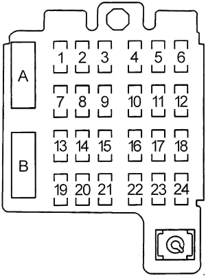
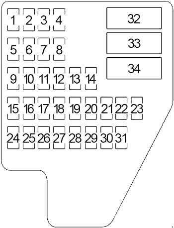
| 1 |
20 |
’95-’97: Stoplights, Hazard Warning Lights, Chime Module |
| 10 |
’98: Headlamp Switch |
| 2 |
20 |
’95-’97: Dome Light, Glove Box Light, Lighted Visor Mirror, Horn, I/P Courtesy Light, Cigar Lighter, Liftgate Glass Release, Power Mirror, Endgate Lock Switch, Keyless Entry, Cargo Lamp, Driver’s Information Display Center, Interior Lamps Control Module, Inside Rear View Mirror |
| 15 |
’98-’05: Cigar Lighter, Data Link Connector (DLC) |
| 3 |
20 |
’95-’97: Electric Shift Transfer Case Module, Parking Lights, License Plate Light, Rear Windshield Washer Pump, Underhood Lamp |
| 10 |
’98-’05: Body Control Module (BCM), Cruise Control Module (CCM), Multifunction Switch (Cruise Control Switch), Seat Lumbar Switch – Driver/Front Passenger |
| 4 |
20 |
’95: Auto Transmission, Alternator Field, Variable Throttle Control, A/C Compressor, Cluster, Chime Module, 4WD Indicator Light, Heated O2 Sensor, Daytime Running Lights Module, Rear Window Defog Switch, Keyless Entry |
| 10 |
’96-’97: A/C Compressor Relay, Daytime Running Lamps Control Module, Daytime Running Lamps Relay, Four Wheel Drive Indicator Switch, Front Axle Switch, Fuel Level Buffer Module, Inflatable Restraint Diagnostic Energy’ Reserve Module, Instrument Ouster, Interior Lamps Control Module, Rear Window Defogger Switch, Remote Control Door Lock Receiver, Seat Belts Lamp Alarm, Ignition Key Lamp Alarm, Transfer Case Select Switch, Transfer Case Shift Control Module |
| 10 |
’98-’05: Body Control Module (BCM), Instrument Panel Cluster (IPC) |
| 5 |
20 |
’95-’97: Linear EGR Valve, Evaporative Emissions Canister Purge Solenoid, Evaporative Emission Canister Vent Solenoid Valve, Heated O2 Sensors, Camshaft Position Sensor, Vehicle Control Module, Powertrain Control Module, Mass Air Flow Sensor |
| 10 |
’98: Radio, Heater Controller (except A/C), Heater and A/C Controller (with A/C), Fog Lamp Switch, IP Module Switch, Truck Body Control Module (TBC), Transfer Case Select Switch, Instrument Cluster |
| 10 |
’99-’05: Body Control Module (BCM), Outside Rear View Mirror Switch, Door Lock and Side Window Switch – Driver/Front Passenger, Side Window Lockout Switch, Rear Seat Audio Control, IP Ashtray Lamp |
| 6 |
25 |
’95: Heater and A/C Select Switch, Air Temperature Valve Electric Actuator |
| 20 |
’96-’97: Air Temperature Valve Electric Actuator, Heater and A/C Controller, Heater Controller |
| 2 |
’99-’05: Redundant Steering Wheel Controls |
| 7 |
25 |
’95-’97: Power Auxiliary Outlets, Data Link Connector |
| 5 |
’98: Outside Rear View Mirror Switch, Door Lock Switch Assembly, Side Window Switch Assembly |
| 10 |
’99-’05: Headlamp Switch |
| 8 |
30 |
’95-’97: Rear Window Defog Switch |
| 10 |
’98-’05: Courtesy Lamps – Left/Right Console, Inadvertent Power Relay, Transfer Case Shift Control Module (NP1) |
| 9 |
15 |
’95: Powertrain Control Module (Battery), ABS Battery, Fuel Pump Relay |
| 20 |
’96-’97: Powertrain Control Module (Battery), Fuel Pump Relay, Fuel Pump Switch and Engine Oil Pressure Gauge Sensor |
| 20 |
’98-’05: Heater and A/C Control Module (with A/C), Heater Controller (except A/C) |
| 10 |
10 |
’95: Powertrain Control Module (Ignition), Injectors, Engine Sensors |
| 20 |
’96-’97: Crankshaft Position Sensor, Electronic Ignition Control Module, Fuel Injectors, Powertrain Control Module |
| 20 |
’98-’05: Multifunction Switch (Hazard Switch) |
| 11 |
20 |
’95-’97: Radio, Inside Rearview Mirror Map Lights, Rear Window Wiper/Washer, Driver Information Display Control Module, Map/Dome Lamp Relay |
| 10 |
’98-’05: Instrument Panel Cluster (IPC), Automatic Transmission Shift Lock Actuator, Automatic Transmission, Powertrain Control Module |
| 12 |
10 |
’96-’97: Cruise Control Module, Cruise Control Switch (Multi-Function Switch), Electronic Brake Control Module (ABS), TCC/Brake And Cruise Control Release Switch |
| 10 |
’98: IP Ashtray Lamp, Truck Body Control Module (TBC), Outside Rear View Mirror Switch, Door Lock Switch Assembly, Side Window Switch Assembly |
| 10 |
’99-’05: Radio, Heater and A/C Control Module, Fog Lamp Switch, Rear Wiper/Washer and Endgate/Liftgate Window Release Switch, Driver Information Center (DIC), Automatic Transmission Shift Lever Position Indicator, Body Control Module (BCM), Transfer Case Select Switch, Instrument Panel Cluster (IPC), Headlamp Leveling Switch |
| 13 |
15 |
’95: Clock, Radio Battery, CD Player |
| 10 |
’96-’97: Radio |
| 20 |
’98-’05: Accessory Power Outlet – Left/Right, Accessory Power Outlet – Floor Console, Accessory Power Outlet – Rear |
| 14 |
5 |
’95: Cluster Illumination, Ash Tray Lamp, Radio Illumination, Heater Lamp, 4WD Illumination, Chime Module, Fog Lamp Sw. Illumination, Daytime Running Lights |
| 10 |
’96-’97: A/C Compressor Relay |
| 15 |
’98-’05: Door Lock Relay, Door Unlock Relay, Door Unlock Relay – Driver (Power Door Locks) |
| 15 |
10 |
’95: Daytime Running Lights Relay |
| 20 |
’96-’97: Fog Lamp Relay, Daytime Running Lights Relay |
| 10 |
’98-’05: Powertrain Control Module (PCM), Transfer Case Shift Control Module, Transfer Case Shift Control Switch (NP1, NP8), Front Axle Vacuum Solenoid (NP1, NP8), Front Axle Indicator Switch (NP1, NP8) |
| 16 |
15 |
’95-’97: Turn Signal Lights, Back-Up Lights, Backup Lamp Switch (Manual Transmission), Transmission Range Switch (Park/Neutral Position and Backup Lamp Switch) |
| 15 |
’98-’05: Inflatable Restraint Sensing and Diagnostic Module (SDM) |
| 17 |
25 |
Windshield Wiper Motor, Multifunction Switch (Wiper Switch) |
| 18 |
15 |
’95: Speedometer, ABS System, Cruise Control |
| 2 |
’99-’05: Redundant Steering Wheel Controls |
| 19 |
20 |
’95-’97: Transfer Case Control Module (Four-Wheel Drive) |
| 15 |
’98-’05: Radio, Instrument Panel Cluster (IPC), Heater and A/C Control Module, Vehicle Interface Unit (VIU) |
| 20 |
10 |
’95: Diagnostic Energy Reserve Module (DERM) |
| 10 |
’96-’97: Clutch Pedal Position and Cruise Control Shutoff Switch, Inflatable Restraint Diagnostic Energy Reserve Module, Transfer Case Shift Control Module, Transmission Range Switch (Park/Neutral Position And Backup Lamp Switch) |
| 25 |
’98-’05: Audio Amplifier |
| 21 |
20 |
’95: Fog Lamps Relay |
| 10 |
’98-’05: Air Temperature Actuator, Heater and A/C Control Module, Inside Rear View Mirror (Automatic Day – Night Mirror), Air Temperature Sensor Assembly – Inside, Vacuum Control Assembly |
| 22 |
10 |
’95-’97: Air Bag Diagnostic Energy Reserve Module (DERM), Arming Sensor |
| 10 |
’98-’05: Stop Lamp Switch, ABS – Electronic Brake Control Module (EBCM) |
| 23 |
10 |
’95-’97: Automatic Transmission Position Indicator Lamp, Driver’s Information Display Center, Endgate Window Release Switch, Fog Lamp Switch, Four Wheel Drive Indicator Switch, Heater and A/C Controller Heater Controller, Instrument Cluster, Liftgate Window Release Switch, Radio, Rear Window Defogger Switch, Rear Window Wiper and Washer Switch, Seat Belts Lamp Alarm, Ignition Key Lamp Alarm |
| 15 |
’98-’05: Rear Wiper/Washer Switch, Endgate/Liftgate Window Release Switch |
| 24 |
10 |
’95-’97: Instrument Cluster, Automatic Transmission, Park Pawl Actuator (Brake Transmission Shift Interlock Solenoid) |
| 10 |
’98-’05: Radio, Driver Information Center (DIC), Rear Seat Audio (RSA) Module, Vehicle Interface Unit (VIU), Outside Rear View Mirror Switch |
Circuit Breaker
|
| A |
20 |
’95-’97: Power Door Locks |
| B |
30 |
’95-’97: Power Windows, Sunroof |