No.
|
A
|
Protected Component |
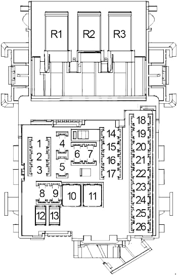
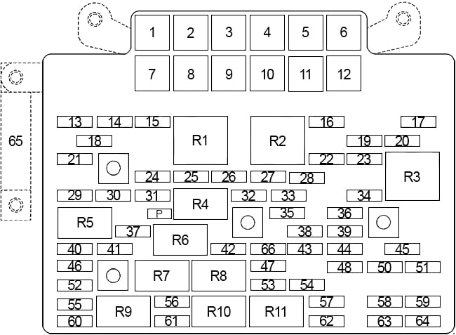
| 1 |
10 |
Gasoline: Right Trailer Stop/Turn Lamp (Trailer Wiring), Auxiliary Body Control Module (XBCM) |
| 2 |
– |
– |
| 3 |
30 |
– |
| 4 |
10 |
Left Trailer Stop/Turn Lamp (Trailer Wiring), Auxiliary Body Control Module (XBCM) |
| 5 |
15 |
Diesel: Mass Air Flow (MAF)/Intake Air Temperature (IAT) Sensor |
| 15 |
Gasoline: Central Sequential Fuel Injection (Central SFI) (4.3L), Evaporative Emissions (EVAP) Canister Purge Solenoid Valve (4.8L/5.3L/6.0L/6.2L), Mass Air Flow (MAF)/Intake Air Temperature (IAT) Sensor (4.8L/5.3L/6.0L/6.2L), Valve Lifter Oil Manifold (VLOM) Assembly (5.3L/6.0L/6.2L), Cooling Fan (Low Speed) Relay (HP2) |
| 6 |
15 |
Gasoline: Engine Control Module (ECM), Evaporative Emission (EVAP) Canister Purse Solenoid Valve (4.3L), Mass Air Flow (MAF)/Intake Air Temperature (IAT) Sensor (4.3L) |
| 7 |
10 |
Diesel: Right Trailer Stop/Turn Lamp (Trailer Wiring), Auxiliary Body Control Module (XBCM) |
| 15 |
Gasoline: Integrated Trailer Brake Control Module |
| 8 |
15 |
Windshield Washer Fluid Pump |
| 9 |
15 |
Diesel (’07-’11): Glow Plug Control Module (GPCM), Fuel Heater |
| 10 |
Gasoline: Heated Oxygen Sensors |
| 10 |
25 |
Electronic Brake Control Module (EBCM) |
| 11 |
10 |
Trailer Wiring, Backup Alarm |
| 12 |
20 |
Headlamp (Left Low Beam) |
| 13 |
10 |
Engine Control Module (ECM) |
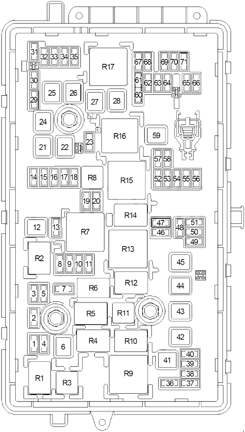
| 14 |
20 |
Gasoline: Fuel Injector (2, 4, 6, 8), Ignition Coil (2, 4, 6, 8) |
| 25 |
Diesel (’07-’10): Engine Control Module (ECM) |
| 30 |
Diesel (’11-’13): Engine Control Module (ECM) |
| 15 |
15 |
Gasoline: Transmission Control Module (TCM), Evaporative Emission (EVAP) Canister Vent Solenoid Valve, Automatic Transmission |
| 15 |
Diesel: Transmission Control Module (TCM), Front Drive Axle Actuator, Glow Plug Control Module (’12-’13) |
| 16 |
10 |
Backup Lamps |
| 17 |
20 |
Headlamp (Right Low Beam) |
| 18 |
10 |
A/C Compressor Clutch |
| 19 |
10 |
Gasoline: Heated Oxygen Sensors |
| 15 |
Diesel: Engine Control Module (ECM), Reductant Sensor Module |
| 20 |
15 |
Gasoline: Transmission Control Module (TCM), 1-2 Shift Solenoid (SS) Valve, 2-3 Shift Solenoid (SS) Valve, 3-2 Shift Solenoid (SS) Valve, Torque Converter Clutch (TCC) Solenoid Valve, Torque Converter Clutch Pulse Width Modulation (TCC PWM) Solenoid Valve, Input Speed Sensor (ISS), Front Drive Axle Actuator, Automatic Transmission, Drive Motor Generator Power inverter module |
| 21 |
20 |
’07-’10: Fuel Pump and Sender Assembly – Front, Fuel Pump |
| 25 |
’11-’13: Fuel Pump and Sender Assembly – Front, Fuel Pump |
| 22 |
20 |
Gasoline: Fuel System Control Module (FSCM) (except 4.3L) |
| 15 |
Diesel: Integrated Trailer Brake Control Module |
| 23 |
– |
– |
| 24 |
– |
– |
| 25 |
20 |
Gasoline (except 4.3L): Fuel Injector (1, 3, 5, 7), Ignition Coil (1, 3, 5, 7) |
| 20 |
Gasoline (4.3L): Ignition Control Module (ICM) |
| 26 |
15 |
Trailer Wiring |
| 27 |
15 |
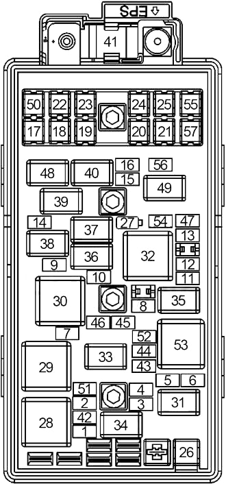
License Lamp (Left), Marker Lamp (Left), Park/Turn Signal Lamp (Left), Tail/Stop and Turn Signal Lamp (Left), Clearance Lamps (Left), Roof Marker Lamps |
| 28 |
15 |
Marker Lamp (Right), Park/Turn Signal Lamp (Right), Tail/Stop and Turn Signal Lamp (Right), License Lamp (Right), Clearance Lamps (Right), Marker Lamp (Tailgate) |
| 29 |
15 |
Front Fog Lamps |
| 30 |
15 |
Horn |
| 31 |
10 |
Headlamp (Right High Beam) |
| 32 |
15 |
Fuse: “34” |
| 33 |
10 |
Headlamp (Left High Beam) |
| 34 |
15 |
Fuse: “12”, “17” |
| 35 |
30 |
Sunroof Module, Roof Beacon Relay |
| 36 |
2 |
Ignition Switch, Theft Deterrent Module (TDM) |
| 37 |
25 |
WIPER CONTROL PCB Relay |
| 38 |
30 |
Emergency Vehicle Roof Lamp Relay |
| 39 |
15 |
PARK ENABLE PCB Relay, ELECTRONIC ADJUSTABLE PEDALS PCB Relay |
| 40 |
10 |
HVAC Control Module |
| 41 |
10 |
Inflatable Restraint Sensing and Diagnostic Module (SDM), Inflatable Restraint Passenger Air Bag On/Off Indicator, Inflatable Restraint I/P Module Disable Switch |
| 42 |
30 |
Audio Amplifier |
| 43 |
15 |
Digital Radio Receiver, Radio, Rear Seat Audio (RSA) Control, Chime Module |
| 44 |
10 |
Auxiliary Body Control Module (XBCM), Stop Lamp Switch, Transfer Case Shift Control Module, Trailer Brake Control Module, Serial Data Gateway (SDG) Module |
| 45 |
15 |
– |
| 46 |
15 |
Inflatable Restraint Passenger Presence System (PPS) Module, Inflatable Restraint Sensing and Diagnostic Module (SDM), Inflatable Restraint Vehicle Rollover Sensor (ASF) |
| 47 |
– |
– |
| 48 |
10 |
Body Control Module (BCM), Instrument Panel Cluster (IPC) |
| 49 |
15 |
Auxiliary Body Control Module (XBCM), Power Take Off Relay (PTO), Run Relay (TP2), Security Indicator Lamp, Vehicle Inclination Sensor, Vehicle Shock Sensor |
| 50 |
10 |
Instrument Panel Cluster (IPC), Inside Rearview Mirror (ISRVM), Heated Steering wheel Module Control |
| 51 |
15 |
Center High Mounted Stop Lamp (CHMSL) |
| 52 |
30 |
Rear Window Defogger |
| 53 |
15 |
Outside Rearview Mirrors (Heater) |
| 54 |
15 |
Auxiliary Body Control Module (XBCM), Security Indicator Lamp, Vehicle Inclination Sensor, Vehicle Shock Sensor |
| 55 |
20 |
Accessory Power Outlet (I/P 1), Data Link Connector (DLC) |
| 56 |
10 |
– |
| 57 |
10 |
Air Temperature Actuators, Mode Actuator, Recirculation Actuator |
| 58 |
15 |
Engine Control Module (ECM), Fuel Pump Relay (Secondary), Fuel Pump Flow Control Module (except 4.3L), Electronic Brake Control Module (EBCM), Fuel System Control Module (Diesel) |
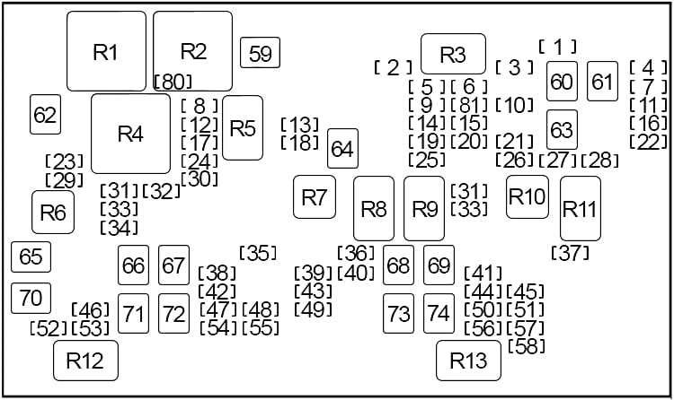
| 59 |
40 |
Gasoline: Cooling Fan (Low Speed) Relay |
| 60 |
40 |
– |
| 61 |
60 |
Electronic Brake Control Module (EBCM) |
| 62 |
40 |
Gasoline: Cooling Fan (High Speed) Relay |
| 63 |
40 |
Electronic Brake Control Module (EBCM) |
| 64 |
40 |
Starter |
| 65 |
30 |
Blunt Cut Wire, Integrated Trailer Brake Control |
| 66 |
60 |
Fuse Block |
| 67 |
30 |
– |
| 68 |
60 |
Windshield Washer Solvent Heater |
| 69 |
30 |
Transfer Case Shift Control Module, Transfer Case Encoder Motor |
| 70 |
40 |
Trailer Wiring |
| 71 |
60 |
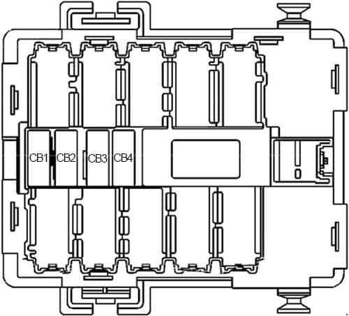
DRIVER SEAT 2 Circuit Breaker, PASS SEAT 1 Circuit Breaker, PWR REAR WNDW Circuit Breaker, RT DOORS Circuit Breaker |
| 72 |
40 |
Blower Motor Control Module |
| 73 |
30 |
– |
| 74 |
60 |
Fuse Block |
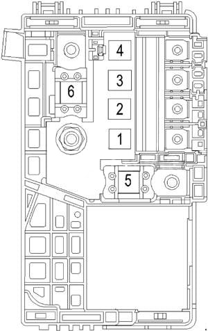
| 80 |
10 |
Diesel: Cooling Fan Relay |
| 81 |
15 |
Diesel: Transmission Control Module (TCM) |
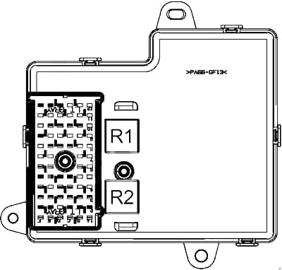
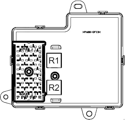
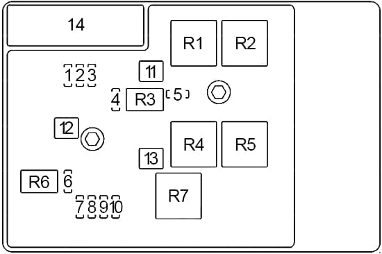
| Relay |
| R1 |
Gasoline: Cooling Fan (High Speed) |
| R2 |
Gasoline: Cooling Fan (Low Speed) |
| R3 |
– |
| R4 |
Gasoline: Cooling Fan Control |
| Diesel: Cooling Fan |
| R5 |
Headlamp (Low Beam) |
| R6 |
Front Fog Lamps |
| R7 |
Air Conditioning Compressor |
| R8 |
Starter |
| R9 |
Powertrain Control Module |
| R10 |
Fuel Pump |
| R11 |
Parking Lamps |
| R12 |
Rear Window Defogger |
| R13 |
Ignition |
| Non-Serviceable |
| R14 |
Back-Up Lamps |
| R15 |
Center High Mounted Stop Lamp |
| R16 |
Daytime Running Lamps |
| R17 |
Washer Fluid Pump (Front) |
| R18 |
Headlamp (High Beam) |
| R19 |
Horn |
| R20 |
Liftgate Release |
| R21 |
Power Door Lock |
| R22 |
Power Door Unlock |
| R23 |
Washer Fluid Pump (Rear) |
| R24 |
Left Trailer Stop Lamp |
| R25 |
Right Trailer Stop Lamp |
| R26 |
Wiper Motor (Control) |
| R27 |
Windshield Wiper Motor (Speed) |