Honda Civic (1992 – 1995) – fuse box diagram

Honda Civic (1992 – 1995) – fuse box diagram


Year of production: 1992, 1993, 1994, 1995

Passenger compartment

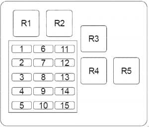
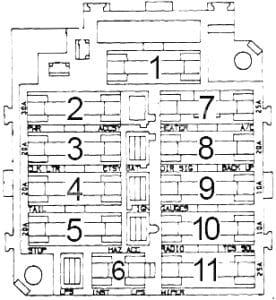
Honda Civic - fuse box diagram - passenger compartment
Honda Civic – fuse box diagram – passenger compartment


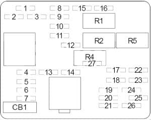
  1. Fuse Box
  2. PGM-FI Relay
  3. Cruise Control Unit
  4. Daytime Running Lights Control Unit
  5. Moon Roof Close Relay
    Moon Roof Open Relay
    M/T: Starter Cut Relay


Passenger compartment fuse box

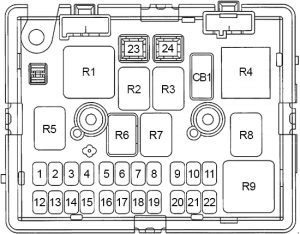
Honda Civic - fuse box diagram - passenger compartment fuse box
Honda Civic – fuse box diagram – passenger compartment fuse box
No. A Circuits
1 30 Moon Roof Motor
2
3 7,5 Integrated Control Unit, Dome Light, Trunk/Cargo Area Light, Data Link Connector (DLC), Option Connector “A”
4 20 Right Rear Power Window Motor
5 20 Right Front Power Window Motor, Power Window Control Unit (del Sol)
20 Left Front Power Window Motor
6 20 Power Door Lock Control Unit
7 20 Left Rear Power Window Motor, Power Window Control Unit (del Sol)
8 20 Left Front Power Window Switch/Motor, Power Window Control Unit (del Sol)
20 Right Front Power Window Motor
9 10 Right High Beam Headlight, Daytime Running Lights Resistor
10 10 Left High Beam Headlight, High Beam Indicator Light, Daytime Running Lights Resistor
11 10 del Sol: Auxiliary Light Relay
12 15 except del Sol: PGM-FI, Alternator, Cruise Control, Gauge Assembly, Electrical Load Detection (ELD) Unit, Vehicle Speed Sensor (VSS)
13 7,5 Power Mirrors, Anti-Lock Brake System, Air Delivery, Blower Motor Relay, Rear Window Defogger Relay, Radiator Fan Relay, Condenser Fan Relay
14 20 Moon Roof Open/Close Relays, Windshield Washer Motor, Rear Window Washer Motor, Integrated Control Unit, Windshield Wiper Motor, Rear Window Wiper Motor, Power Window Relay
15 10 Clock, Gauge Assembly, Hazard Switch, Back-Up Lights, Interlock System, Integrated Control Unit, Roof Unlatched Indicator (del Sol), Shift Lock Solenoid, A/T Gear Position Switch, Master Switch (del Sol)
16 7,5 Daytime Running Lights Control Unit, Option Connector “C”
17 10 Daytime Running Lights Control Unit, Option Connector “B”
18 7,5 PGM-FI, Integrated Control Unit, Engine Control Module (ECM)
19 10 Dash Lights, Dimming Signal, Parking Lights, Tail Lights, License Plate Lights, Console Lights, Option Connector “D”
20
21 10 Right Low Beam Headlight, Auxiliary Light Switch (del Sol)
22 10 Left Low Beam Headlight
23 15 Stereo Radio/Cassette or CD Player, Cigarette Lighter, Option Connector “E”
24 15 PGM-FI, Alternator, Cruise Control, Gauge Assembly, SRS Control Unit, Vehicle Speed Sensor (VSS)
25 10
Relay
R1 Power Window
R2 except del Sol ’94-’95: Turn Signal Hazard


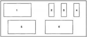
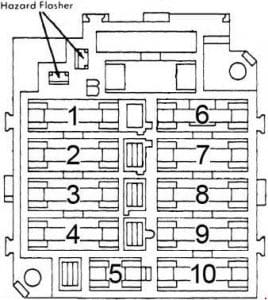
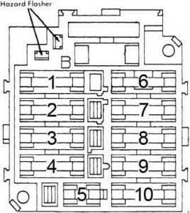
Honda Civic - fuse box diagram - passenger compartment
Honda Civic – fuse box diagram – passenger compartment
  1. Fuse Box
  2. Cruise Control Unit
    Daytime Running Lights Control Unit
  3. Auxiliary Light Relay
    PGM-FI Main Relay
    M/T: Starter Cut Relay
    Turn Signal Flasher


Engine Compartment

Honda Civic - fuse box diagram - engine compartment
Honda Civic – fuse box diagram – engine compartment


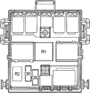
  1. Fuse Box
  2. Daytime Running Lights Resistor
  3. A/C Compressor Clutch Relay
    A/C Condenser Fan Relay
  4. with ABS: Relay Box


Engine Compartment Fuse Box

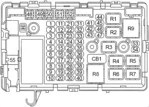
Honda Civic - fuse box diagram - engine compartment fuse box
Honda Civic – fuse box diagram – engine compartment fuse box
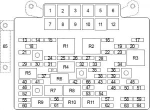
No. A Circuits
31 15 PGM-FI Electronic Control Unit, PGM-FI Main Relay
32 7,5 PGM-FI Electronic Control Unit / Engine Control Module (ECM), Clock, Stereo Radio/Cassette Player
33 15 Radiator Fan Relay
34 30 Rear Window Defogger
15 Rear Window Defogger
35 20 Condenser Fan Motor, A/C Compressor Clutch
36 50 Power Distribution To Fuse No. 1, 3 & 6, Power Windows, Option Connector “A”
37 30 Blower Motor
38
39 50 Ignition Switch (Bat)
40 40 Combination Light Switch, Fuse No. 17, Daytime Running Lights
41 80 Power Distribution (Main Fuse)
42 20 Horns, Brake Lights, Key Interlock Solenoid, Cruise Control, Engine Control Module (ECM)
15 Horns, Brake Lights, Key Interlock Solenoid
43 10 Turn Signal Lights, Turn Signal/Hazard Relay, Hazard Warning Switch
44
45
46
Relay
R1 Rear Window Defogger
R2 Blower Motor
R3 Radiator Fan

Engine Compartment Fuse Box (’94-’95)

Honda Civic - fuse box diagram - engine compartment fuse box
Honda Civic – fuse box diagram – engine compartment fuse box


No. A Circuits
31 15 PGM-FI Main Relay
32 7,5 Engine Control Module (ECM), Clock, Stereo Radio/Cassette Player
33 15 Radiator Fan Relay
34 30 Rear Window Defogger
15 del Sol: Rear Window Defogger
35 20 Condenser Fan Motor, A/C Compressor Clutch
36 50 Power Distribution To Fuse Nos. 1, 3 & 6, Power Windows, Option Connector “A”
37 30 Blower Motor
38
39 50 Ignition Switch (Bat)
40 40 Combination Light Switch, Fuse No. 17
41 80 Power Distribution (Main Fuse)
42 20 Horns, Brake Lights, Key Interlock Solenoid
15 del Sol: Horns, Brake Lights, Key Interlock Solenoid
43 10 Turn Signal Lights, Turn Signal/Hazard Relay
44
45
46
Relay
R1 Radiator Fan
R2 Blower Motor
R3 Rear Window Defogger

Engine Compartment Relay Box (with ABS)

Honda Civic - fuse box diagram - engine compartment relay box
Honda Civic – fuse box diagram – engine compartment relay box
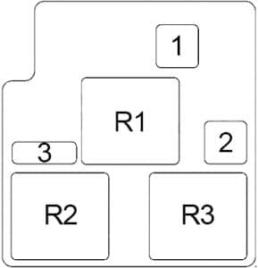
No. A Circuits
51 50 ABS Pump Motor
52
53
54 15 ABS Control Unit (+B2)
55 20 ABS Control Unit (+B1)
56
57 7,5 ABS Control Unit
58
Relay
R1 ABS Pump Motor
R2 Rear ABS Fail-Safe
R3 Front ABS Fail-Safe

WARNING: Terminal and harness assignments for individual connectors will vary depending on vehicle equipment level, model, and market.

Honda Civic (1996 – 2000) – fuse box diagram

Honda Civic (1996 – 2000) – fuse box diagram


Year of production: 1996, 1997, 1998, 1999, 2000

Passenger compartment

Honda Civic - fuse box diagram - passenger compartment
Honda Civic – fuse box diagram – passenger compartment
  1. Fuse Box
  2. Interlock Control Unit
  3. Transmission Control Module (TCM/CVT)
    Keyless Door Lock Control Unit

Passenger compartment fuse box

Honda Civic - fuse box diagram - passenger compartment fuse box
Honda Civic – fuse box diagram – passenger compartment fuse box
No. A Circuits
1
2
3 10 Rear Wiper, Security System
4 10 Right Headlight (High Beam), Daytime Runing Lights (DRL) Control Unit
5 10 Left Headlight (High Beam), Daytime Runing Lights (DRL) Control Unit
6 Security System
7 20 Left Rear Window Motor
8 20 Right Rear Window Motor
9 15 ‘98-‘00 (except GX): Ignition Coil
10 20 Front Passenger’s Window Motor
11 20 Driver’s Window Motor
12 7,5 Hazard Warning Switch
13 15 PGM-FI Main Relay, Supplemental Restraint System (SRS) Unit
14 7,5 Stereo Radio Tuner (’96-’98), Cruise Control Main Switch, Keyless Door Lock Control Unit (’99-’00)
15 7,5 Electrical Load Detector (ELD) Unit, Gauge Assembly, Transmission Control Module – TCM (’96-’98 CVT), PGM-FI, Vehicle Speed Sensor (VSS)
16 7,5 Rear Window Defogger (’96-’98), ABS Control Unit, Power Mirror Switch (’99-’00)
17 7,5 Power Mirrors (’96-’98), Air Delivery, Blower Controls, A/C Compressor Controls, Fans
18 7,5 Daytime Runing Lights (DRL) Control Unit
19 7,5 Back-Up Lights
20 7,5 Daytime Runing Lights (DRL) Control Unit
21 10 Right Headlight (Low Beam)
22 10 Left Headlight (Low Beam)
23 10 Supplemental Restraint System (SRS) Unit
24 7,5 Power Window Relay, Moonroof
25 7,5 Integrated Control Unit, Interlock System, Gauge Assembly
26 20 Front Wiper/Washer
27 10 ’96-’98: Accessory Power Socket
15 ’99-’00: Accessory Power Socket
28 10 ’96-’97: Stereo Radio Tuner
15 ’98: Stereo Radio Tuner
10 ’99-’00: Audio Unit
29
30 7,5 Dash & Console Lights
31 7,5 PGM-FI Main Relay, Powertrain/Engine Control Module (PCM/ECM), Integrated Control Unit
32 7,5 Parking Lights, License Plate Lights, Tail Lights
33 7,5 Interlock System
Relay
R1 Rear Window Defogger
R2 Power Window
R3 Turn Signal / Hazard


Honda Civic - fuse box diagram - passenger compartment
Honda Civic – fuse box diagram – passenger compartment
  1. Injector Control Module
  2. Cruise Control Unit
  3. Fuel Injector Relay
  4. Dash Lights Brightness Controller
  5. Starter Cut Relay
  6. Horn Relay

Engine Compartment

Honda Civic - fuse box diagram - engine compartment
Honda Civic – fuse box diagram – engine compartment
  1. Relay Box
  2. Fuse Box

Engine Compartment Fuse Box

Honda Civic - fuse box diagram - engine compartment fuse box
Honda Civic – fuse box diagram – engine compartment fuse box
No. A Circuits
41 80 Power Distribution
42 40 Ignition Switch (BAT)
43 7,5 Ceiling Light, Data Link Connector
44 20 GX: PGM-FI Main Relay, Injector Control Module (Fuel Injector Relay)
15 except GX: PGM-FI Main Relay, Injector Control Module (Fuel Injector Relay)
45
46 40 Power Window Motors (Power Window Relay)
47 7,5 Audio Unit (’99-’00), Clock, PCM (VBU), Stereo Audio Tuner (’96-’98), Transmission Control Module (’96-’98), Heater Control Panel
48 30 Combination Light Switch (Headlight), Fuse: No.33
49
50 30 Rear Window Defogger (Rear Window Defogger Relay)
51 20 Power Door Lock Control Unit (’99-’00), Keyless Door Lock Control Unit (’99-’00), Moonroof
52 15 Horn System, Brake Lights, Brake Signal
53 10 Hazard Warning Light, Turn Signal/Hazard Relay
54 40 Security System (Option)
55 40 Blower Motor (Blower Motor Relay)
56 20 Condenser Fan Motor (Condenser Fan Relay), A/C Compressor Clutch (A/C Compressor Clutch Relay)
57 20 Radiator Fan Motor (Radiator Fan Relay)
Relay
R1 Condenser Fan
R2 A/C Compressor Clutch
R3 Radiator Fan
R4 Blower Motor

Engine Compartment Relay Box

Honda Civic - fuse box diagram - engine compartment relay box
Honda Civic – fuse box diagram – engine compartment relay box
No. A Circuits
61 40 ABS Pump Motor
62 20 ABS Control Unit
63 7,5 ABS Control Unit
Relay
R1 ABS Pump Motor

WARNING: Terminal and harness assignments for individual connectors will vary depending on vehicle equipment level, model, and market.

Honda Pilot (2003 – 2008) – fuse box diagram

Honda Pilot (2003 – 2008) – fuse box diagram

Year of production: 1999, 2000, 2001, 2002, 2003, 2004, 2005, 2006, 2007, 2008, 2009

Passenger compartment

Honda Pilot - fuse box diagram - passenger compartment
Honda Pilot – fuse box diagram – passenger compartment
  1. Fuse Box No.1
  2. Rear Accessory Power Socket Relay
  3. Interior Light Relay
  4. ’03-’05: Front Fog Light Relay
    ’06-’08: Low Beam Cut Relay
  5. Daytime Running Light Control Unit
  6. ’06-’08: Windshield Washer Motor Relay
  7. Shift Lock Relay
  8. P Pin Relay
  9. PGM-FI Main Relay No.1
  10. PGM-FI Main Relay No.2 (Fuel Pump)
  11. Rear Blower Motor Relay
  12. ’03-’05: Dimmer Relay
    ’06-’08: Daytime Running Light Relay
  13. Taillight Relay
  14. 4WD: Variable Torque Management 4WD System (VTM-4) Relay
    2WD (’06-’08): Engine Mount Control Relay

Passenger compartment fuse box no. 1

Honda Pilot - fuse box diagram - passenger compartment fuse box no. 1
Honda Pilot – fuse box diagram – passenger compartment fuse box no. 1
No. A Circuits
1 15 Immobilizer Control Unit-Receiver, Powertrain Control Module (PCM), PGM-FI Main Relay No.2 (Fuel Pump), Supplemental Restraint System (SRS) Unit
2 10 Supplemental Restraint System (SRS) Unit
3 7,5 A/C Compressor Clutch Relay, Blower Motor Relay, Climate Control Unit, Heater Control Panel, Powertrain Control Module (PCM), Recirculation Control Motor, Rear Blower Motor Relay, Near Mode Motor, Rear Window Defogger Relay, Radiator Fan Control Module (’03-’05)
4 7,5 AC Inverter Unit (’06-’08), Power Mirror Actuator, Power Mirror Deforgger, ABS Modulator-Control Unit (’03-’05), Variable Torque Management 4WD System (VTM-4) (’03-’05)
5 10 Daytime Running Light Control Unit
6 15 Alternator, Cruise Control Main Switch Indicator Light, Evaporative Emission Control (EVAP) Canister Purge Valve, Gauge Control Module, Powertrain Control Module (PCM), VSA Modulator-Control Unit (’06-’08), Electrical Load Detector (ELD) Unit (’03-’05), Secondary Heated Oxygen Sensors (’03-’05), Radiator Fan Control Module (’03-’05), Variable Torque Management 4WD System (VTM-4) (’03-’05), VTM-4 Relay (’03-’05)
7 7,5 Electrical Compass Mirror (’06-’08), Occupant Detection System (ODS) Unit Passenger’s Cutoff Indicator, Automatic Dimming Inside Mirror (’06-’08), Rear Window Intermittent Wiper Relay, Rear Window Wiper/washer Switch, Rear Window Wiper Motor, Front Fog Light (’06-’08)
8 7,5 Accessory Power Socket Relay, Active Noise Control Rear Microphone (2WD) (’06-’08), Active Noise Control Unit (2WD) (’06-’08), Gauge Control Module, Optional Keyless Connector (’06-’08), Rear Accessory Power Socket Relay, Shift Lock Relay
9 10 Active Noise Control Unit (2WD) (’06-’08), A/T Reverse Relay, Back-up Lights, Brake Light Failure Sensor, Gauge Control Module, Keyless Receiver Unit, Navigation Unit (’06-’08), Automatic Dimming Inside Mirror (’06-’08), Optional Security Connector (’06-’08), Passenger’s Multiplex Control Unit, Shift Lock Solenoid (’06-’08), Variable Torque Management 4WD System (VTM-4) Lock Switch Indicator Light (4WD), Variable Torque Management 4WD System (VTM-4) Control Unit, Driver’s Multiplex Control Unit
10 7,5 Turn Signal/Hazard Relay
11 7,5 ’06-’08: Variable Torque Management 4WD System (VTM-4) Control Unit
15 ’03-’05: Ignition Coils
12 30 Rear Window Washer Motor Relay, Windshield Wiper Motor, Windshield Intermittent Wiper Circuit, Windshield Washer Motor, Windshield Intermittent Wiper Relay
13 7,5 PGM-FI Main Relay, Powertrain Control Module (PCM)

View of Back Side

Honda Pilot - fuse box diagram - passenger compartment fuse box no. 1 (back side)
Honda Pilot – fuse box diagram – passenger compartment fuse box no. 1 (back side)
No. Relay
R1 Starter Cut
R2 Reverse
R3 Turn Signal/Hazard
Honda Pilot - fuse box diagram - passenger compartment
Honda Pilot – fuse box diagram – passenger compartment


  1. Immobilizer Control Unit-Receiver
  2. 2WD (’06-’08): Active Noise Control Unit
  3. Keyless Receiver Unit
  4. Air Fuel Ratio (A/F) Sensor Relay
  5. Ignition Relay
  6. Throttle Actuator Control Module Relay
  7. ’06-’08: Rear Washer Motor Relay
  8. Fuse Box No.2
  9. Supplemental Restraint System (SRS) Unit
  10. 2WD (’06-’08): Engine Mount Control Unit

Passenger Compartment Fuse Box No.2

Honda Pilot - fuse box diagram - passenger compartment fuse box no. 2
Honda Pilot – fuse box diagram – passenger compartment fuse box no. 2
No. A Circuits
1 20 Power Window Control Unit
2 20 Driver’s Power Seat Front Up-Down Motor (EX-L), Driver’s Power Seat Slide Motor (EX-L) Driver’s Power Seat Rear Up-Down Motor (Except EX-L), Driver’s Power Seat Recline Motor (Expert EX-L)
3 20 Front Seat Heaters
4 20 Driver’s Power Seat Rear Up-Down Motor (EX-L), Driver’s Power Seat Recline Motor (EX-L), Driver’s Power Seat Rear Up-Down Motor (Except EX-L), Driver’s Power Seat Slide Motor (Except EX-L)
5
6 10 Daytime Running Lights Control Units
7 20 Left Rear Window Motor, Power Window Master Switch, Power Window Control Unit
8 20 Front Passenger’s Window Motor
9 15 Audio Unit, DVD Player Unit (with Rear Entertainment System), Console Accessory Power Socket, Front Accessory Power Socket, Navigation Unit, Navigation Display Unit, Cigarette Lighter Connector
10 15 Audio Unit Light, Auxiliary Jack Assembly Light (with Rear Entertainment System), Cruise Control Main Switch Light, Climate Control Unit Light, DVD Player Unit (with Rear Entertainment System), Driver’s Multiplex Control Unit, Front Parking Lights, Front Side Marker Lights, Front Console Light, Front Door Lock Switches Light, Gauge Control Module Lights, Glove Box Light, Hazard Warning Switch Light, Heater Control Panel Lights, Interior Lights Switch Light, License Plate Lights, Moonroof Switch Light, Navigation Display Unit, Navigation Unit, Cigarette Lighter Connector, Fog Light Connector (driver’s Under-dash Fuse/relay Box), Power Mirror Switch Light, Rear Heater-A/C Control Unit Light, Rear Controller and Screen (with Rear Entertainment System), Roof Console Light, Seat Heater Switches Light, Taillight Relay, Taillights, Trailer Lighting Connector, VTM-4 Locks Switch Light
11 10 Front Individual Map Lights, Front Door Courtesy Lights, HomeLink, Interior Lights Relay, Navigation Display Unit, Navigation Unit, Rear Individual Map Lights, Tailgate Light, Vanity Mirror Lights
12 20 Passenger’s Multiplex Control Unit
13 7,5 Driver’s Multiplex Control Unit, Door Multiplex Control Unit, Gauge Control Module, Immobilizer Control Unit-Receiver, Immobilizer Indicator, Keyless Receiver Unit, Security Connector, Security Indicator, Passenger’s Multiplex Control Unit
14 7,5 ’06-’08: Moonroof Close Relay, Moonroof Open Relay
15 20 ’06-’08: Moonroof Close Relay, Moonroof Motor, Moonroof Open Relay
16 20 Right Rear Window Motor
Auxiliary Holder
7,5 Radiator Fan Relay

View of Back Side

Honda Pilot - fuse box diagram - passenger compartment fuse box no. 2 (back side)
Honda Pilot – fuse box diagram – passenger compartment fuse box no. 2 (back side)
No. Relay
R1 Power Window
R2 Accessory Power Socket
R3 Rear Window Defogger
Honda Pilot - fuse box diagram - passenger compartment
Honda Pilot – fuse box diagram – passenger compartment


  1. Rear Controller and Screen (with Rear Entertainment System)
  2. Variable Torque Management 4WD System (VTM-4) Control Unit
  3. Moonroof Close Relay
  4. Moonroof Open Relay
Honda Pilot - fuse box diagram - passenger compartment
Honda Pilot – fuse box diagram – passenger compartment


  1. XM Receiver (XM Radio)
  2. Imoes Unit


Engine Compartment

Honda Pilot - fuse box diagram - engine compartment
Honda Pilot – fuse box diagram – engine compartment


  1. Powertrain Control Module (PCM)
  2. Fuse Box No.1
  3. Fuse Box No.2
  4. ABS or VSA Modulator-Control Unit
  5. Relay Box


Engine compartment fuse box no.1

Honda Pilot - fuse box diagram - engine compartment fuse box no. 1
Honda Pilot – fuse box diagram – engine compartment fuse box no. 1
No. A Circuits
41 120 Battery, Power Distribution
42 50 Ignition Switch, Optional Keyless Connector
43 20 Combination Light Switch, Daytime Running Lights Control Unit, Right Headlights
44
45 20 Combination Light Switch, Daytime Running Lights Control Unit, Left Headlights, High Beam Indicator Light, Fog Light (’06-’08)
46 15 Data Link Connector (DLC), PGM-FI Main Relay
47 20 Breake Lights, Drive’s Multiplex Control Unit, High Mount Brake Light, Horn Relay, Horns, Ignition Key Light, Key Interlock Solenoid, Powertrin Control Module (PCM), Trailer Lighting Connector
48 20 Audio Unit, DVD Player Unit (rear Entertainment System), Rear Controller And Screen (rear Entertainment System)
49 15 Hazard Warning Lights
50 20 ’03-’05: Trailer Lighting Connector
51 40 Power Window Relay, Fuse (Passenger Compartment Fuse Box No.2): No. 1
52 40 Fuses (Passenger Compartment Fuse Box No.2): No.2, 3, 4, 6
53 30 Noise Condenser, Rear Window Defogger
54 40 Fuse (Passenger Compartment Fuse Box No.2): No.9, 10, 11, 12, 13
55 30 Rear Blower Motor
56 40 Blower Motor
57 30 Radiator Fan Motor
58 30 A/C Condenser Fan Motor
59 7,5 A/C Compressor Clutch
* * Spare Fuse
Relay
R1 Headlight No.1 (Right)
R2 Headlight No.2 (Left)
R3 Horn
R4 A/C Condenser Fan
R5 Blower Motor
R6 Radiator Fan
R7 A/C Compressor Clutch

Engine compartment fuse box no. 2

Honda Pilot - fuse box diagram - engine compartment fuse box no. 2
Honda Pilot – fuse box diagram – engine compartment fuse box no. 2
No. A Circuits
1 20 AC Inverter Unit
2 40 VSA Modulator-Control Unit
3 30 VSA Modulator-Control Unit
4 20 Variable Torque Management 4WD System (VTM-4) Control Unit
5 10 2WD: Engine Mount Control Unit
6 15 Console Accessory Power Socket, Rear Accessory Power Socket
7 15 Powertrain Control Module (PCM)
8 15 Ignition Coils
9 15 Air Fuel Ratio (A/F) Sensors (Bank 1, Bank 2), Secondary Heated Oxygen Sensors (Bank 1, Bank 2), Electrical Load Detector (ELD) Unit
10 7,5 Tire Pressure Monitoring System (TPMS) Control Unit
11 20 Front Fog Light, Gauge Control Module, Fog Light Connector, Fog Light Switch Connector

Engine Compartment Relay Box

Honda Pilot - fuse box diagram - engine compartment relay box
Honda Pilot – fuse box diagram – engine compartment relay box
No. Relay
R1 Fan Control
R2 Rear Window Intermittent Wiper
R3 Windshield Intermittent Wiper
R4 Seat Heater

WARNING: Terminal and harness assignments for individual connectors will vary depending on vehicle equipment level, model, and market.

Honda S2000 (1999 – 2009) – fuse box diagram

Honda S2000 (1999 – 2009) – fuse box diagram

Year of production: 1999, 2000, 2001, 2002, 2003, 2004, 2005, 2006, 2007, 2008, 2009

Passenger compartment

Honda S2000 - fuse box diagram - passenger compartment
Honda S2000 – fuse box diagram – passenger compartment
  1. Fuse Box
  2. Engine Control Module (ECM)
  3. ’06-’09: Electronic Throttle Control System (ETCS) Control Relay
  4. High Beam  Cut Relay
  5. ’00-’01: Intermittent Wiper Relay
    ’02-’09: Rear Window Defogger Relay
  6. Keyless Door Lock Control Unit
  7. ’00-’05: Cruise Control Unit
  8. ’06-’09: Throttle Actuator Control Module

Passenger compartment fuse box

Honda S2000 - fuse box diagram - passenger compartment fuse box
Honda S2000 – fuse box diagram – passenger compartment fuse box
No. A Circuits
1 10 Supplemental Restraint System (SRS) Unit
2 15 Supplemental Restraint System (SRS) Unit, Fuel Pump, Immobilizer Control Unit-Receiver (’06-’09), PGM-FI Main Relay (’00-’05), Fuel Tank Unit, Passenger’s Airbag Cut-Off Indicator, Passenger’s Weight Sensor Unit
3 7,5 Clutch Interlock Switch, Engine Start Switch, Starter Cut Relay, Starter Solenoid
4 15 ’00-’05: Ignition Coils
5 7,5 Back-up Lights, Charging System Light (’04-’05), Daytime Running Light (DRL) Indicator, Electronic Power Steering (EPS) Control Unit, Gauge Assembly, Keyless Door Lock Control Unit, Convertible Top Control Unit
6 15 Air Control Solenoid Valve, Alternator, Charging System Indicator (’00-’03), Cruise Control Unit, Cruise Control Main Switch, Electrical Load Detector (ELD) Unit, Evaporative Emission Control (EVAP) Bypass Solenoid Valve, EVAP Canister Vent Shut Valve, EVAP Canister Purge Valve, Primary and Secondary Heated Oxygen Sensors, Rear Window Defogger Change Relay (’02-’05)
7 7,5 Turn Signal/Hazard Relay
8 20 Power Window Master Switch, Windshield Wiper Motor, Intermittent Wiper Relay
9 10 Accessory Power Socket, Audio Unit, Radio Remote Switch, Convertible Top Switch Light
10 7,5 ’06-’09: Air Fuel Ratio (A/F) Sensor Relay (LAF)
11 7,5 ’06-’09: Electronic Throttle Control System (ETCS) Control Relay
12 15 Windshield Washer Motor, Convertible Top Switch
13 7,5 Intermittent Wiper Driving Circuit (in the Gauge Assembly)
14 15 ’06-’09: Throttle Actuator Control Module
15 20 ’06-’09: Air Fuel Ratio (A/F) Sensor No.1, Evaporative Emission Control (EVAP) Canister Vent Shut Valve
16 15 ’06-’09: Ignition Coils, Ignition Coil Relay
17 20 Driver’s Window Motor
18 20 Passenger’s Window Motor, Convertible Top Control Unit
19 7,5 ABS Modulator-Control Unit (’00-’05), Daytime Running Lights Control Unit, Power Mirror Actuator, Rear Window Defogger Relay
20 7,5 A/C Compressor Clutch Relay, Blower Motor Relay, A/C Condenser Fan Relay, Heater Control Panel, Radiator Fan Relay, Recirculation Control Motor
21 7,5 Engine Control Module (ECM), PGM-FI Main Relay (’00-’05), Tire Pressure Monitoring System (TPMS) Control Unit
22 15 Audio Unit
23 10 Taillight Relay, Audio Unit Light, Cruise Control Main Switch Light, Front Parking Lights, Gauge Lights, Hazard Warning Switch Light, Heater Control Panel Lights, Keyless Door Lock Control Unit, License Plate Light, Option Connector, Convertible Top Switch Lights, Radio Remote Switch Lights, Rear Side Marker Lights, Taillights, Rear Window Defogger Switch Light, Passenger’s Airbag Cutoff Indicator Illumination Light (’06-’09), VSA Off Switch Light
24 7,5 Ceiling/Spotlights, Trunk Light
25 7,5 Engine Control Module (ECM), Gauge Assembly, Heater Control Panel, Immobilizer Indicator Light, Convertible Top Control Unit, Immobilizer Control Unitreceiver (’06-’09), XM Receiver, Immobilizer System Indicator
26 15 Keyless Door Lock Control Unit, Trunk Lid Opener Solenoid
27 10 Daytime Running Lights Control Unit
28
Relay
R1 Turn Signal / Hazard
R2 ’00-’01 (Hardtop): Rear Window Defogger
R3 Starter Cut
R4 Taillight
Honda S2000 - fuse box diagram - passenger compartment
Honda S2000 – fuse box diagram – passenger compartment


  1. Ignition Coil Relay
  2. Air Fuel Ratio (A/F) Sensor Relay
  3. ’00-’05: PGM-FI Main Relay
  4. ’06-’09: PGM-FI Main Relay No.1
  5. ’06-’09: PGM-FI Main Relay No.2
  6. Daytime Running Lights Control Unit
  7. Daytime Running Lights Subcontrol Unit
  8. Convertible Top Control Unit
  9. Audio Unit
  10. Supplemental Restraint System (SRS) Unit
  11. Ignition (IG2) Relay
  12. Accessory Power Socket Relay
Honda S2000 - fuse box diagram - passenger compartment
Honda S2000 – fuse box diagram – passenger compartment


  1. Power Window Master Switch
  2. ’02-’09: Rear Window Defogger Change Relay


Engine compartment

Honda S2000 - fuse box diagram - engine compartment
Honda S2000 – fuse box diagram – engine compartment


  1. Fuse Box No.1
  2. Electronic Power Steering (EPS) Control Unit
  3. ’02-’05: Intermittent Wiper Relay
  4. Fuse Box No.2
  5. ’06-’09: Intermittent Wiper Relay
  6. ABS(VSA (’06-’09)) Modulator-Control Unit
  7. ’00-’05: Air Pump Relay

Engine compartment fuse box no.1

Honda S2000 - fuse box diagram - engine compartment fuse box 1
Honda S2000 – fuse box diagram – engine compartment fuse box 1


No. A Circuits
41 100 Battery, Power Distribution
42 40 Ignition Switch (BAT)
43 20 Right Headlight (High/Low Beam), Daytime Running Lights Control Unit
44
45 20 Left Headlight (High/Low Beam), Daytime Running Lights Control Unit, Gauge Assembly, High Beam Indicator, High Beam Cut Relay
46 15 Data Link Connector (DLC), PGM-FI Main Relay (’00-’05), Crankshaft Position (CKP) Sensor (’06-’09), Camshaft Position (CMP) Sensor (’06-’09), Engine Control Module (ECM (’06-’09))
47 10 ’00-’01: ABS Modulator-Control Unit, Brake Lights, Cruise Control Unit, Engine Control Module (ECM), High Mount Brake Light, Horn
15 ’02-’09: ABS Modulator-Control Unit (’02-’05), Brake Lights, Cruise Control Unit (’02-’05), Engine Control Module (ECM), High Mount Brake Light, Horn
48 20 ’00-’05: ABS Modulator-Control Unit
30 ’06-’09: VSA Modulator-Control Unit
49 10 Hazard Warning Lights
50 30 ’00-’05: ABS Modulator-Control Unit
30 ’06-’09: VSA Modulator-Control Unit
51 40 Fuses: No. 17, 18
52 20 Right Convertible Top Motor
53 20 ’08-’09: Accessory Power Socket Relay
54 20 Fuses: No. 22, 23, 24, 25, 26, 27
55 20 Left Convertible Top Motor
56 40 Blower Motor
57 20 Radiator Fan Motor
58 20 A/C Condenser Fan Motor, A/C Compressor Clutch
59 20 Fuses: No. 14, 15, 16
* * Spare Fuse
Relay
R1 Right Headlight
R2 Left Headlight
R3 Horn
R4 A/C Condenser Fan
R5 Blower Motor
R6 Radiator Fan
R7 A/C Compressor Clutch

Engine compartment fuse box no. 2

Honda S2000 - fuse box diagram - engine compartment fuse box 2
Honda S2000 – fuse box diagram – engine compartment fuse box 2
No. A Circuits
32 60 ’00-’05: Air Pump Electric Current Sensor
33 70 Electronic Power Steering (EPS) Control Unit
34 20 Rear Window Defogger
35
36

WARNING: Terminal and harness assignments for individual connectors will vary depending on vehicle equipment level, model, and market.

Honda Crosstour (2010 – 2015) – fuse box diagram

Honda Crosstour (2010 – 2015) – fuse box diagram

Year of production: 2010, 2011, 2012, 2013, 2014

Passenger compartment

Honda Crosstour - fuse box diagram - passenger compartment
Honda Crosstour – fuse box diagram – passenger compartment


  1. HandsFreeLink Control Unit
  2. Fuse Box No.1
  3. Driver’s Multiplex Integrated Control Unit (MICU)
  4. Driver’s Junction Box
  5. Gauge Control Module


Passenger compartment fuse box no. 1

Honda Crosstour - fuse box diagram - passenger compartment fuse box no 1
Honda Crosstour – fuse box diagram – passenger compartment fuse box no 1
No. A Circuits
1
2 7,5 Power Seat Control Unit (with Driving Position Memory System (DPMS))
3 15 Rear Window Washer Motor Relay, Windshield Washer Motor Relay, Windshield/Rear Window Washer Motor (Washer Motor Relays)
4 7,5 Rear Window Wiper Motor (Rear Window Wiper Motor Relay), Windshield Wiper Motor Relay
5 7,5 Automatic Dimming Inside Mirror, Reverse Rela, Driver’s Multiplex Integrated Control Unit (MICU), Back-up Light, Electrical Compass Unit, Gauge Control Module, Navigation Unit, Passenger’s Multiplex Integrated Control Unit (MICU), Shift Lock Solenoid, Tire Pressure Monitoring System (TPMS) Control Unitt
6 7,5 VSA Modulator-Control Unit, Yaw Rate-acceleration Sensor
7 15 Active Control Engine Mount (ACM) Control Relay, Alternator, Brake Pedal Position Switch, Powertrain Control Module – PCM (VBSOL), Electrical Load Detector (ELD), Engine Mount Control Unit, Evaporative Emission Control (EVAP) Canister Purge Valve
8 7,5 3.5L (J35Z): Powertrain Control Module – PCM (STS – Starter Signal)
9 20 Powertrain Control Module – PCM (IG1), Fuel Pump (PGM-FI Main Relay No.2), Immobilizer-Keyless Control Unit
10 10 Powertrain Control Module – PCM (VBSOL2)
11 10 Supplemental Restraint System (SRS) Unit
12 7,5 Front Passenger’s Airbag Cutoff Indicator, Occupant Detection System (ODS) Unit, Supplemental Restraint System (SRS) Unit
13
14 10 3.5L (J35Z): Engine Mount Control Unit (Active Control Engine Mount (ACM) Control Relay)
15 7,5 Daytime Running Light (DRL), Driver’s Multiplex Integrated Control Unit (MICU)
16 7,5 A/C Compressor Clutch Relay, A/C Condenser Fan Relay (3.5L), Audio-HVAC Display Unit, Audio-HVAC Subdisplay Unit, Blower Motor Relay, Climate Control Unit, Door Multiplex Control Unit, Driver’s Climate Control Switch, Driver’s Seat Heater Switch, Fan Control Relay, Front Passenger’s Seat Heater Switch, Navigation Display Unit, Passenger’s Climate Control Switch, Power Mirror Switch, Rear Window Defogger Relay, HVAC Control Unit (2.4L), Rearview Mirror With Rearview Camera Display, Radiator Fan Relay (2.4L)
17 7,5 Driver’s Multiplex Integrated Control Unit (MICU) (ACC Key Lock)
18 7,5 Audio Unit, Audio-HVAC Display Unit, Audio-HVAC Subdisplay Unit, Cargo Area Accessory Power Socket Relay, Console Accessory Power Socket Relay, Front Accessory Power Socket Relay, Front HFLANC/Active Sound Control Microphone, Front HFL-Navigation-ANC/Active Sound Control Microphone, HandsFreeLink Control Unit, Interface Dial, Key Interlock Solenoid, Navigation Display Unit, Navigation Unit, Power Seat Control Unit
19 20 Driver’s Power Seat Front Up-Down Motor, Driver’s Power Seat Slide Motor, Driver’s Power Seat Adjustment Switch, Power Seat Control Unit
20 20 Moonroof Control Unit/Motor
21 20 Driver’s Power Seat Rear Up-Down Motor, Driver’s Power Seat Adjustment Switch, Driver’s Power Seat Recline Motor
22 20 Left Rear Power Window Motor, Left Rear Power Window Switch, Power Window Relay
23 15 Front Accessory Power Socket (Accessory Power Socket Relay)
24 20 Door Multiplex Control Unit
25 10 Driver’s Door Lock Actuator, Fuel Fill Door Lock Actuator, Left Rear Door Lock Actuator, Power Door Lock Relays, Tailgate Release Actuator, Tailgate Release Actuator Relay
26 10 Left Fog Light, Driver’s Multiplex Integrated Control Unit (MICU), Fog Light Relay
27 10 Left Front Parking Light, Left Front Side Marker Light, Left Taillight, License Plate Lights, Right Taillight, Taillight Relay, Driver’s Multiplex Integrated Control Unit (MICU)
28 10 Left Headlight High Beam
29 7,5 Tire Pressure Monitoring System (TPMS) Control Unit
30 15 Left Headlight Low Beam
31 7,5
Relay
R1 PGM-FI Main No.2 (Fuel Pump)
R2 Front Accessory Power Socket
R3 Starter Cut No.1
Honda Crosstour - fuse box diagram - passenger compartment
Honda Crosstour – fuse box diagram – passenger compartment


  1. Navigation Display Unit
  2. Climate Control Unit (with Navigation System)
  3. Audio Amplifier
  4. Fuse Box No.2 / Passenger’s Multiplex Integrated Control Unit (MICU)
  5. Audio/HVAC Subdisplay Unit (with Navigation System)
    Climate Control Unit (without Navigation System)
  6. Audio Unit

Passenger compartment fuse box no. 2

Honda Crosstour - fuse box diagram - passenger compartment fuse box no 2
Honda Crosstour – fuse box diagram – passenger compartment fuse box no 2


No. A Circuits
1 10 Right Headlight High Beam
2 10 Right Front Parking Light, Right Front Side Marker Light, Taillight Relay, Fuse (Fuse Box No.2) No.6, Passenger’s Multiplex Integrated Control Unit (MICU)
3 10 Right Fog Light, Fog Light Relay, Passenger’s Multiplex Integrated Control Unit (MICU)
4 15 Right Headlight Low Beam
5
6 7,5 A/T Gear Position Indicator Panel Light, Ambient Light, Audio-HVAC Display Unit Light, Audio-HVAC Subdisplay Unit Light, Climate Control Unit Light, Driver’s Seat Heater Switch Light, Driver’s Climate Control Switch, Front Passenger’s Seat Heater Switch Light, Glove Box Light, Hazard Warning Switch/passenger’s Airbag Cutoff Indicator Light, HomeLink Unit, Moonroof Switch Light, Navigation Display Unit, Navigation Unit, Passenger’s Climate Control Switch, Steering Wheel Switch Lights, VSA OFF Switch Light
7
8 20 Front Passenger’s Power Seat Recline Motor, Front Passenger’s Power Seat Adjustment Switch
9 20 Front Passenger’s Power Seat Slide Motor, Front Passenger’s Power Seat Adjustment Switch
10 10 Front Passenger’s Door Lock Actuator, Power Door Lock Relays, Right Rear Door Lock Actuator
11 20 Right Rear Power Window Motor, Right Rear Power Window Switch
12 15 Console Accessory Power Socket (Console Accessory Power Socket Relay)
13 20 Front Passenger’s Power Window Switch
14
15 20 Audio Amplifier
16 15 Cargo Area Accessory Power Socket (Cargo Area Accessory Power Socket Relay)
17
18 10 Driver’s Lumbar Support Motor, Driver’s Lumbar Support Switch
19 15 Driver’s Seat Heater, Seat Heater Relays, Front Passenger’s Seat Heater
20
21
22


  1. Immobilizer-Keyless Control Unit
  2. Tire Pressure Monitoring System (TPMS) Control Unit
  3. Center Junction Box
  4. Cargo Area Accessory Power Socket Relay
  5. Supplemental Restraint System (SRS) Unit
  6. Console Accessory Power Socket Relay
  7. Engine Mount Control Unit


  1. Electrical Compass Unit
  2. Moonroof Control Unit/Motor
  3. XM Receiver
  4. Navigation Unit


Engine compartment


  1. Fuse Box
  2. Powertrain Control Module (PCM)
  3. SA Modulator Control Unit

Engine compartment fuse box no. 1


No. A Circuits
1.1 120 3.5L (J35Z): Battery, Power Supply
100 2.4L (K24A): Battery, Power Supply
1.2 40 Fuse (Passenger Compartment Fuse Box No.2): No. 8, 9, 10, 11, 12, 13
2.1 70
2.2 40 VSA Modulator-Control Unit
2.3 30 VSA Modulator-Control Unit
2.4 40 Fuse (Passenger Compartment Fuse Box No.2): No. 15, 16, 17, 18, 19
2.5 30 Headlight Washer Motor, Headlight Washer Relay
2.6
3.1 50 Ignition Switch
3.2 40
3.3 30 Fuse (Passenger Compartment Fuse Box No.2): No. 1, 2, 3, 4
3.4 60 Fuse (Passenger Compartment Fuse Box No.1): No. 14, 19, 20, 21, 22, 23, 24, 25
3.5 30 Fuse (Passenger Compartment Fuse Box No.1): No. 26, 27, 28, 29, 30
3.6 30 Radiator Fan Motor, Radiator Fan Relay
3.7 30 Windshield Wiper Motor, Windshield Wiper Motor Relay, Windshield Wiper Motor Intermittent Relay, Windshield Wiper Hi/Low Relay
3.8 30 3.5L (J35Z): A/C Condenser Fan Motor, A/C Condenser Fan Relay
4 75 Radiator Fan Relay
5 40 Rear Window Defogger Relay, Lower Rear Window Defogger, Noise Reduction Condenser, Upper Rear Window Defogger
6 20 2.4L (K24A): A/C Condenser Fan Relay
7 15 Hazard Warning Switch, Driver’s Multiplex Integrated Control Unit (MICU)
8 20 Stop Lamp Switch, Brake Pedal Position Switch, Powertrain Control Module – PCM, High Mount Brake Light, Horn Relay, Trailer Lighting Connector
9
10
11 15 Ignition Coil Relay, Ignition Coils
12 15 PGM-FI Subrelay, Evaporative Emission Control (EVAP) Canister Vent Shut Valve, Front Air Fuel Ratio (A/F) Sensor, Front Secondary Heated Oxygen Sensor (HO2S) (Bank 1, Sensor 2), Rear Air Fuel Ratio (A/F) Sensor (Bank 2, Sensor 1), Rear Secondary Heated Oxygen Sensor (HO2S) (Bank 2, Sensor 2), Fuse No.4
13
14
15 10 Audio Unit, AUDIO-HVAC Display Unit, AUDIO-HVAC Subdisplay Unit, Back-Up Light, Data Link Connector (DLC), Door Multiplex Control Unit, Driver’s Door Courtesy Light, Driver’s Multiplex Integrated Control Unit (MICU), Front HFLANC/Active Sound Control Microphone, Front HFL-Navigation-ANC/Active Sound Control Microphone, Front Passenger’s Door Courtesy Light, Gauge Control Module, HandsFreeLink Control Unit, Immobilizer-Keyless Control Unit, Navigation Display Unit, Navigation Unit, Passenger’s Multiplex Integrated Control Unit (MICU), Power Mirror Control Unit, Power Seat Control Unit
16 7,5 Ceiling Light, Driver’s Vanity Mirror Light, HomeLink Unit, Ignition Key Light, Individual Map Light, Left Cargo Area Light. Passenger’s Vanity Mirror Light, Right Cargo Area Light
17 15 PGM-FI Main Relay No.1, Crankshaft Position (CKP) Sensor, Camshaft Position (CMP) Sensor, Electronic Throttle Control System (ETCS) Control Relay, Injectors, Mass Airflow (MAF) Sensor, Powertrain Control Module – PCM (IGP), PGM-FI Main Relay No.2
18 15 Electronic Throttle Control System (ETCS) Control Relay
19 75 3.5L (J35Z): Powertrain Control Module – PCM (VBUM)
20 40 3.5L (J35Z): Blower Motor, Blower Motor Relay
40 2.4L (K24A): A/C Compressor Clutch, A/C Compressor Clutch Relay
21 7,5 3.5L (J35Z): A/C Compressor Clutch, A/C Compressor Clutch Relay
7,5 2.4L (K24A): A/C Condenser Fan Relay
Relay
R1 Blower Motor
R2 Horn
R3 PGM-FI Main
R4 GM-FI Sub
R5 Ignition Coil
R6 Electronic Throttle Control System (ETCS) Control
R7 A/C Condenser Fan
R8 Rear Window Defogger
R9 A/C Compressor Clutch

WARNING: Terminal and harness assignments for individual connectors will vary depending on vehicle equipment level, model, and market.

Honda Passport (1998 – 2002) – fuse box diagram

Honda Passport (1998 – 2002) – fuse box diagram

Year of production: 1998, 1999, 2000, 2001, 2002

Passenger Compartment Fuse Box

Honda Passport - fuse box diagram - passenger compartment
Honda Passport – fuse box diagram – passenger compartment
No. A Circuits
1 20 Accessory Power Sockets
2 15 Clock, Stereo Sound System
3 10 Starting System
4 15 Taillight Relay (A/T Gear Position Indicator, Alarm and Relay Controls, Dash and Console Lights, Fuel Injection System, Headlight Switch, Lights-on Reminder, Multiplex Control System, Parking Light, Tail Light, License Light, Power Door Locks/Keyless Entry/Security System, Trailer Lights Connector)
5 10 Alarm and Relay Controls, Cargo Light, Ceiling Light, Courtesy Lights, Dome Light Relay (’01), Ignition Key Reminder (LX), Map Light
6 15 ABS, Automatic Transmission Controls, Brake Lights, Cruise Control, Interlock System, Trailer Lighting Connector
7 20 Ignition Key Reminder (EX), Power Door Locks/Keyless Entry/Security System
8 10 Power Mirror Defoggers
9 15 Rear Window Defogger
10 15 Rear Window Defogger
11 15 ABS, Gauges, Indicators, Interlock System, Multiplex Control System
12 15 Automatic Transmission Controls, Fuel Injection System, Starting System
13 15 Ignition System
14 15 Automatic Transmission Controls, Back-up Lights, Cruise Control, Map Light Timer (’01), Multiplex Control System, Shift-on-the-fly System (’01-’02), Transmission Range Switch
15 15 Alarm and Relay Control Unit, Blower Controls, Power Moonroof, Power Windows, Shift-on-the-fly System (’00), Trailer Lighting Connector, Turn Signal Lights
16 10 Alarm and Relay Control Unit, Rear Window and Mirror Defoggers, Rear Wiper/Washer
17 20 Alarm and Relay Control Unit, Windshield Wiper/Washer
18 10 Power Mirrors, Stereo Sound System
19 15 Accessory Power Sockets, Cigarette Lighter
20 10 Security and Keyless Entry System
21 30 Power Moonroof, Power Seat (’01-’02), Power Windows
22 10 SRS
23
Relay
R1 Taillight
R2
R3 Accessory Power Socket
R4 Power Window
R5 ’01: Dome Light
R6 Rear Window Defogger
Diode
D1 Ceiling Lights, Keyless Entry and Security System
D2 Keyless Entry and Security System

Engine Compartment Fuse Box (Type 1)

Honda Passport - fuse box diagram - engine compartment (type 1)
Honda Passport – fuse box diagram – engine compartment (type 1)
No. A Circuits
1 15 Hazard Warning Lights, Trailer Lighting Connector
2 10 Alarm and Relay Control Unit, Data Link Connector (DLC), Security Horn
3 10 Alternator
4
5 15 Blower Controls
6 15 Blower Controls
7 10 Air Delivery
8 10 Left Headlights, Fog Lights
9 10 Right Headlight
10 15 Fog Lights
11 20 Heated Oxygen Sensors
12 20 Fuel Pump
13 15 Automatic Transmission Controls, Fuel Injection System, Gauges
14 Daytime Running Lights
15 60 Fuel Injection System, Power Distribution (BAT)
16 100 A/C Compressor Controls, Blower Controls, Charging System, Fog Lights, Power Distribution (BAT), Starting System
17 30 Engine Control Module
18 50 ABS
19 50 Power Distribution (BAT)
20 30 Condenser Fan
Relay
R1 Fuel Pump
R2
R3 Headlight
R4 Starter
R5 Condenser Fan
R6
R7
R8 A/C Thermo
R9 Engine Control Module (ECM) (M/T)
Powertrain Control Module (PCM) (A/T)
R10
R11 Fog Light
R12 Heater-A/C
R13 A/C Compressor
Diode
D1 Brake System Indicator Light

Engine Compartment Fuse Box (Type 2)

Honda Passport - fuse box diagram - engine compartment (type 2)
Honda Passport – fuse box diagram – engine compartment (type 2)
No. A Circuits
F-1 15 Hazard warning light
F-2 10 Alarm & relay control unit, Horn, Anti – theft horn
F-4 20 Blower motor, Blower resistor
F-5 10 A/C thermostat relay, Electronic thermostat, A/C compressor relay, Magnetic clutch
F-6
F-7
F-8 10 Headlight – LH, High beam indicator light, Fog light relay
F-9 10 Headlight – RH
F-10 15 Fog light
F-11 20 Oxygen sensor
F-12 20 Fuel pump
F-13 15 Engine control module
F-14
FL1 60 EHCU
FL2 30 Condenser fan unit
FL3
FL4 100 Ignition switch, starter relay, A/C, generator, heater relay, Fuse: F10, FL1, FL2, FL5, FL6
FL:5 60 Ignition switch, fuel pump relay, engine control module relay, power train module
FL6
Relay
X1 Headlight
X2 Fog light
X3 Starter
X4 A/C compressor
X5 Thermo
X6 Heater
X7 Fuel pump
X8 Engine control module
X9 6VD1: Condenser fan
X10
Diode
1 Brake
2
3
4

WARNING: Terminal and harness assignments for individual connectors will vary depending on vehicle equipment level, model, and market.

Mitsubishi Raider (2005 – 2009) – fuse box diagram

Mitsubishi Raider (2005 – 2009) – fuse box diagram

Year of production: 2005, 2006, 2007, 2008, 2009

Fuse box diagram

Mitsubishi Raider - fuse box diagram
Mitsubishi Raider – fuse box diagram
No. A Circuits
1
2 40 ←’07: Ignition Switch (Windows/Door Lock Circuit Breaker, Fuse: “22”)
3 30 Brake Provision Module
4 50 Driver Seat Switch
5 40 ←’07: Ignition Switch (Rear Window Defogger Relay, Fuse: “57”, “58”, “59”, “60”, “61”)
6 20 Radio, Cluster, Electronic Overhead Module, Satellite Receiver, Front Control Module, Cabin Compartment Node (CCN)
7 10 Powertrain Control Module, Air Conditioner Compressor Clutch Relay, Fuel Pump Relay, Sentry Key Remote Entry Module, Fuse: “8”, “46”
8 10 Cluster, Transfer Case Selector Switch, Inside Rearview Mirror, Cabin Compartment Node (CCN)
9 10 ←’07: Occupant Classification Module
10 20 ’07→: Ignition Switch (Sentry Key Remote Entry Module)
11 10 Air Conditioner Compressor Clutch Relay
12 15 Left Trailer Tow Relay
13 15 Right Trailer Tow Relay
14 20 ←’07: Data Link Connector, Hands-Free Module, Sentry Key Remote Entry Module, Electronic Overhead Module
15 25 Transmission Control Relay, Powertrain Control Module
16 20 Horn Relay
17 20 ABS (Valves)
18 20 Fuel Pump Relay
19 15 Stop Lamp Switch, Center High-Mounted Stop Light (CHMSL)
20 20 Cluster, Door Locks, Cabin Compartment Node (CCN), Shift Motor/Mode Sensor Assembly (4WD), Brake Transmission Shift Interlock (BTSI)
21 15 ←’07: Audio Amplifier
25 ’07→: Audio Amplifier
22 20 Power Outlet – Instrument Panel
23 20 Fog Lamp Relay
24 20 Powertrain Control Module
25 15 Cluster, Cabin Compartment Node (CCN) Illumination
26 20 ’07→: Run/Start Relay
27 10 Mirror Switch
28 20 Power Outlet – Console
29 20 Wipers, Front Control Module (FCM)
30
31 30 ’07→: Ignition ACC Relay (Window/Door Lock Circuit Breaker (Power Window, Door Lock, Sunroof, Subwoofer Amplifier), Fuse: “22”)
32 30 Front Control Module (Exterior Lights No.1)
33 30 Automatic Shut Down Relay (Powertrain Control Module, Ignition Coil, Fuel Injector, Ignition Capacitor)
34 30 Front Control Module (Exterior Lights No.1)
35 40 Blower Motor Relay (Heating Ventilation Air Conditioning)
36 10 ←’07: Powertrain Control Module, Ignition Unlock/Run/Start
37 10 ←’07: Starter Relay
38 20 ←’07: Ignition Switch
39 30 Starter Solenoid, Powertrain Control Module, Front Control Module, Starter Relay
40 40 ’07→: Ignition RUN Relay
41 30 Wipen On/Off Relay, Wiper High/Low Relay
42 25 Front Control Module (Transfer Case)
43 10 Park/Turn Lamp – Front Left, Tail/Stop/Turn Lamp – Left
44 10 Park/Turn Lamp – Front Right, Tail/Stop/Turn Lamp – Right
45 20 Trailer Tow
46 10 Occupant Restraint Controller Module, Passenger Airbag On/Off Indicator Lamp, Occupant Classification Module (←’07)
47 40 ←’07: Ignition Switch (Cluster)
48 20 Sunroof/Sound Box
49 30 Trailer Tow
50 40 Anti-Lock Brake System (ABS) Module (Pump)
51 40 Park Lamp Relay (Fuse: “43”, “44”, “45”), Front Control Module
52
53 40 Rear Window Defogger Relay (Rear Window Defogger, Fuse: “56”)
54
55 10 ←’07: Cluster
56 10 Heated Mirrors
57 20 Occupant Restraint Controller Module
58 20 Heated Seat
59 10 Heating Ventilation Air Conditioning (HVAC) Module, A/C Heater Control, Rear Window Defogger Relay
60 10 Anti-Lock Brake System (ABS) Module
61 20 Front Control Module (Reverse Lamps)
Relay
R1 Right Trailer Tow
R2 Left Trailer Tow
R3 Air Conditioner Compressor Clutch
R4 Horn
R5 Transmission Control
R6 Park Lamp
R7 Fuel Pump
R8 Fog Lamp
R9
R10 Rear Window Defogger
R11 ’07→: Ignition – RUN
R12 Wiper High/Low
R13 Wiper On/Off
R14 Starter
R15 Automatic Shut Down
R16 ’07→: Blower Motor
75 ’07→: Ignition – ACC

WARNING: Terminal and harness assignments for individual connectors will vary depending on vehicle equipment level, model, and market.

Hyundai i30n (2018 – 2019) – fuse box diagram

Hyundai i30n (2018 – 2019) – fuse box diagram

Year of production: 2018, 2019

Driver’s side fuse panel

Hyundai i30n - fuse box diagram - driver's side fuse panel
Hyundai i30n – fuse box diagram – driver’s side fuse panel
Fuse Fuse name Symbol A Description
F1 MODULE 5 7,5 Electro Chromic Mirror, MTS E-Call Module, Audio, A/V & Navigation Head Unit, A/C Control Module, A/T Shift Lever Indicator, Console Switch RH, DC-DC Converter, Head Lamp LH/RH, Auto Head Lamp Levelling Device Module, Front Seat Warmer Control Module, Driver IMS Module
F2 MODULE 3 7,5 Driver/Passenger Door Module, BCM
F3 SUNROOF 1 20 Panorama Sunroof
F4 TAILGATE 10 Tail Gate Relay
F5 POWER WINDOW LH 25 Power Window LH Relay, Driver/Passenger Safety Window Module, Rear Safety Window Module LH
F6 MULTIMEDIA 15 Audio, A/V & Navigation Head Unit, DC-DC Converter
F7 POWER
WINDOW RH
25 Power Window RH Relay, Driver/Passenger Safety Window Module, Rear Safety Window Module RH
F8 POWER
SEAT DRIVER
25 Driver Seat Manual Switch, Driver IMS Module
F9 POWER SEAT
PASSENGER
25 Passenger Seat Manual Switch
F10 MODULE 4 7,5 Lane Keeping Assist Module, Stop Lamp Switch, BCM, LSD ECU, ESC Unit
F11 SMART KEY 2 7,5 Smart Key Control Module, Immobiliser Module
F12 SUNROOF 2 20 Panorama Sunroof
F13 INTERIOR
LAMP
7,5 Wireless Charger, Vanity Lamp LH/RH, Room Lamp, Overhead Console Lamp, Personal Lamp LH/RH, Rain Sensor, Ignition Key Ill. & Door Warning Switch, Glove Box Lamp, Luggage Lamp, Rain sensor
F14 MEMORY 2 7,5 MTS E-Call Module
F16 MEMORY 1 10 Driver/Passenger Door Module, Driver IMS Module, BCM, A/C Control Module, Instrument Cluster, Auto Light & Photo Sensor, ICM Relay Box (Outside Mirror Folding/Unfolding Relay)F17
F17 E-LSD E-LSD 20 LSD ECU
F18 ECS ECS 15 ECS Unit
F19 MODULE 6 7,5 Smart Key Control Module, BCM
F20 MDPS 7,5 MDPS Unit, Steering Angle Sensor
F21 MODULE 1 7,5 Hazard Switch, Centre Door Lock Switch, Driver/Passenger Door Module, Driver/Passenger Power Outside Mirror, Driver/Passenger Smart Key Outside Handle, Data Link Connector
F22 MODULE 7 7,5 Front Seat Warmer Control Module, ESG Unit, Cooling Fan Motor, Nozzle Heater
F23 AIRBAG
INDICATOR
7,5 Instrument Cluster, Centre Door Lock Switch
F24 BRAKE
SWITCH
7,5 Smart Key Control Module, Stop Lamp Switch
F25 START 7,5 Smart Key Control Module, Engine Room Junction Block (RLY.4)
F26 CLUSTER CLUSTER 7,5 Instrument Cluster
F27 DOOR LOCK 20 Door Lock/Unlock Relay, ICM Relay Box (Dead Lock Relay)
F30 SEAT HEATER
FRONT
20 Front Seat Warmer Control Module
F31 AIR
CONDITIONER 2
10 A/C Control Module, ECM, Blower Motor, Engine Room Junction Block (RLY.10)
F32 AIR
CONDITIONER 1
7,5 A/C Control Module, Engine Room Junction Block (RLY.10/11)
F33 SMART KEY 1 1-smart-key 15 Smart Key Control Module, Immobiliser Module
F35 AIRBAG 15 SRS Control Module
F36 IGNITION 1 25 PCB Block (F45/F46/F47)
F37 MODULE 2 10 Wireless Charger, MTS E-Call Module, Smart Key Control Module, BCM, Audio, A/V & Navigation Head Unit, DC-DC Converter, Power Outside Mirror Switch, Engine Room Junction Block (RLY.14F38)
F38 WASHER 15 Multifunction Switch
F39 WIPER 10 ECM, BCM
F40 REAR WIPER 15 Rear Wiper Relay
F42 MIRROR
HEATED
10 Driver/Passenger Power Outside Mirror, A/C Control Module, ECM/PCM
F43 POWER
OUTLET
POWER
OUTLET
20 Rear Power Outlet #2
F45 HEATED
STEERING
15 BCM

Engine compartment fuse panel

Hyundai i30n - fuse box diagram - engine compartment
Hyundai i30n – fuse box diagram – engine compartment
Relay Symbol Relay name
RLY.3 PDM #3 (IG1) Relay
RLY.4 START Relay
RLY.5 E-CVVT E-CVVT Relay
RLY.6 PDM #4 (IG2) Relay
RLY.7 FUEL PUMP Relay
RLY.8 PDM #2 (ACC) Relay
RLY.10 BLOWER Relay
RLY.11 PTC HEATER PTC HEATER #1 Relay
RLY.12 REAR DEFOGGER Relay
RLY.14 POWER OUTLET POWER OUTLET Relay


Fuse Fuse name Symbol A Description
F1 MAIN MAIN 180 Fuse : F27, F29, F30, F33
F2 MDPS 1 100 MDPS Unit
F3 B+5 60 PCB Block (Fuse : F44, F50, F51, F52, Engine Control Relay)
F4 B+2 60 IGPM (Fuse : F30, IPS0, IPS1, IPS2)
F5 B+3 60 IGPM (IPS3, IPS4, IPS5, IPS6, IPS7, IPS8)
F6 B+4 60 IGPM (Fuse : F3, F4, F5, F7, F8, F9, F12, F17, F18)
F8 REAR
HEATED
40 RLY.12
F9 BLOWER 40 RLY.10
F10 IGNITION 1 40 Ignition Switch, Engine Room Junction Block (RLY.3, RLY8)
F11 IGNITION 2 40 Ignition Switch, Engine Room Junction Block (RLY.4, RLY6)
F12 COOLING FAN 80 Cooling Fan Motor
F13 PTC
HEATER 1
50 RLY.11
F17 POWER
OUTLET 3
20 Rear Power Outlet
F18 POWER OUTLET 2 20 Rear Power Outlet
F21 VACUUM PUMP 1 20 Vacuum Pump
F22 FUEL PUMP FUEL PUMP 20 RLY.7
F24 B+1 40 IGPM (Leak Current Autocut Device, Fuse : F21, F24, F27, F33)
F27 BURGLAR
ALARM HORN
10 ICM Relay Box (Burglar Alarm Horn Relay)
F29 ABS1 40 ESP Control Module
F30 ABS2 30 ESP Control Module
F31 E-CVVT 3 3 E-CVVT 40 RLY.5
F33 POWER OUTLET 1 40 RLY.14
F34 E-CVVT1 1 E-CVVT 10 ECM
F35 E-CVVT2 2 E-CVVT 20 ECM

Engine compartment fuse panel (Battery terminal cover)

Hyundai i30n - fuse box diagram - engine compartment (battery terminal cover)
Hyundai i30n – fuse box diagram – engine compartment (battery terminal cover)

WARNING: Terminal and harness assignments for individual connectors will vary depending on vehicle equipment level, model, and market.

Lifan Breez (2005 – 2017) – fuse box diagram

Lifan Breez (2005 – 2017) – fuse box diagram

Year of production: 2005, 2006, 2007, 2008, 2009, 2010, 2011, 2012, 2013, 2014, 2015, 2016, 2017

Passenger Compartment Fuse Panel

Lifan 520 (Breez) - fuse box diagram - passenger compartment
Lifan 520 (Breez) – fuse box diagram – passenger compartment
Number A Description
1 25 Spare
2 25 Terminal 15 1)
25 Cluster 2)
3 10 Cluster
4 5 ABS 1)
5 Spare 2)
5 10 Stop Lamp, Back-up lamps
10 Back-up lamps 2)
6 10 Air Bag 1)
10 Stop Lamp 2)
7 30
8 15 Hazard Warning System 1)
15 Turn Signals 2)
9 20
10 15 Low Beam 1)
20 Low Beam 2)
11 10 Audio System
15 Audio System 2)
12 10 Side Lamp
13 10 Turn Signals 1)
10 azard Warning System 2)
14 5 Electric fuel injection ECU 1)
10 Electric fuel injection ECU 2)
15 5 Cluster illumination 1)
5 Indicator closed doors 2)
16 5
17 15 Front Wiper Motor
18 10 Audio System
19 30 Window Lift
20 15 Cigar Lighter
21 10 Fuel pump
22 15 Central locking 1)
15 — 2)
23 15 High Beam
24 15 Heated Rear Window
25 10 Interior Lighting
26 15
27 20 Fog lights 1)
15 Rear Fog Light 2)
28 15 Hhead lights 1)
20 Fog Light 2)
29 30 Ignition AM 1)
30 Climate (Blower Motor, Air Conditioning) 2)
Relay
R1 High Beam
R2 Side Lamp
R3 Low Beam
R4 Turn Signals
R5
R6 Front Wiper Motor
R7 Fuel pump
R8 Heated Rear Window
R9 Fog Light
1) Owner Manuals (Mexico; 2010 year)
2) Owner Manuals (Russia; 2008 year)

Fuse Box In The Engine Compartment

1.3 L (LF479Q3) & 1.6 L (LF481Q3)

Lifan 520 (Breez) - fuse box diagram - engine compartment
Lifan 520 (Breez) – fuse box diagram – engine compartment -1.3 L (LF479Q3) & 1.6 L (LF481Q3)

1.6 L TRITEC

Lifan 520 (Breez) - fuse box diagram - engine compartment
Lifan 520 (Breez) – fuse box diagram – engine compartment – 1.6 L TRITEC
Number A Description
1 15 Horn relay
25 25 Main relay
3 10 A/C compressor
4 15 1.3 & 1.6: Cooling fan high speed 1
5 20 1.3 & 1.6: Cooling fan high speed 2
6 20 1.3 & 1.6: Cooling fan low speed
30 Fan
30 ABS
7 30 1.6 L TRITEC: Fan
8 30 1.6 L TRITEC: Cooling fan low speed
9 30 1.6 L TRITEC: Cooling fan low speed
10 1.6 L TRITEC: Not Used
11 1.6 L TRITEC: Not Used
12 50 1.6 L TRITEC: Terminal 15
13 50 1.6 L TRITEC: Terminal 30
Relay
R1 Main relay
R2 Cooling fan high speed 2
R3 Cooling fan high speed 1
R4 Cooling fan low speed
R5 A/C compressor
R6 Horn

WARNING: Terminal and harness assignments for individual connectors will vary depending on vehicle equipment level, model, and market.

Lexus GX460 (J150) (2009 – 2013) – fuse box diagram

Lexus GX460 (J150) (2009 – 2013) – fuse box diagram

Year of production: 2009, 2010, 2011, 2012, 2013

Engine compartment fuse box

Lexus GX460 - fuse box diagram - engine compartment
Lexus GX460 – fuse box diagram – engine compartment
Fuse [A] Circuit protected
1 A/C RR 40 Rear air conditioning system
2
3 AIR SUS 50 Air suspension system, AIR SUS NO.2
4 INV 15 Inverter
5
6 DEF 30 Rear window defogger
7
8 DEICER 20 Windshield wiper deicer
9
10
11 SUB BATT 30 Towing
12
13 IG2 20 Injector, ignition, meter
14 HORN 10 Horn
15 EFI 25 EFI ECU, A/F heater relay, fuel pump relay, EFI NO.2
16 A/F 20 A/F SSR
17
18 FUEL OPN 10 Fuel lid opener
19 S/HTR RR 20 Rear seat heater
20 FOLD SEAT LH 30 Folding seat (left)
21 FOLD SEAT RH 30 Folding seat (right)
22 TOWING TAIL 30 Towing
23
24 A/C COMP 10 Air conditioning system
25 STRG HTR 10 Steering heater
26 CDS FAN 20 Condenser fan
27 STOP 10 Stop lights, high mount stop light, stop light switch, stop lights relay, VSC ECU, towing, Smart access system with push button start
28
29 AIR SUS NO.2 7,5 AIR SUS ECU
30 H-LP RH-HI 15 Headlight high beam (right)
31 H-LP LH-HI 15 Headlight high beam (left)
32 HTR 50 Air conditioning system
33 WIP WSH RR 30 Rear window wipers and washer
34 H-LP CLN 30 Headlight cleaner
35
36 400W INV 80 AC INVERTER
37 ST 30 STARTER MTR
38 H-LP HI 25 DIM relay, headlights, daytime running light system
39 ALT-S 7,5 ALT
40 TURN & HAZ 15 Front turn signal light, rear turn signal light, side turn signal light, meter turn signal light
41 D/L NO.1 25 Door lock motor, glass hatch) opener
42 ETCS 10 EFI ECU
43 FUEL PMP 15 FPC
44
45 TOWING 30 Towing
46 ALT 140 Air conditioning system, AIR SUS, headlight cleaner, towing, folding seat, STOP, rear window defogger, MIR HTR, CDS FAN, RR FOG, DEICER, ALT CON, MG-CLT, RR SEAT HTR, STRG HTR, J/B, RR WIP, RR WSH
47 P/l-B 80 Injector, ignition, meter, EFI, A/F heater, horn
48
49 RAD NO.1 15 Audio system, navigation system, rear seat entertainment system
50 AM2 7,5 Starter system
51 RAD NO.2 10 Navigation system
52 MAYDAY 7,5 MAYDAY
53 AMP 30 Audio system
54 ABS NO.1 50 ABS, VSC
55 ABS NO.2 30 ABS, VSC
56 AIR PMP 50 Air pump
57 SECURITY 10 Security horn, self power siren, double lock ECU
58 SMART 7,5 Smart access system with push button start
59 STRG LOCK 20 Steering lock system
60 TOWING BRK 30 Towing
61 WIP RR 15 Rear window wiper
62 DOME 10 Interior lights, personal lights, vanity lights, door courtesy lights, footwell lights, outer foot lights, overhead module
63 ECU-B 10 Body ECU, meter, Fieater, steering sensor, wireless remote control, seat position memory, tilt and telescopic steering, multi display, Smart access system with push button start, folding seat, cool box, DSS#2 ECU, steering switch, D-module switch, overhead module
64 WSH FR NO.2 7,5 DSS#1 ECU
65 H-LP RH-LO 15 Headlight low beam (right), headlight leveling system
66 H-LP LH-LO 15 Headlight low beam (left), headlight leveling system
67 INJ 10 Coil, injector, ignition, noise filter
68 EFI NO.2 10 02 SSR, AFM, ACIS VSV, Al COMB, KEY OFF PUMP, EYP VSV, EGR VALVE, CANISTER VSV, Al VSV RLY, Al PUMP HTR RLY
69 WIPFR NO.2 7,5 DSS#1 ECU
70 WSH RR 15 Rear window washier
71 SPARE Spare fuse
72 SPARE Spare fuse
73 SPARE Spare fuse

Passenger Compartment Fuse Box

Lexus GX460 - fuse box diagram - passenger compartment
Lexus GX460 – fuse box diagram – passenger compartment
Fuse Ampere rating [A] Circuit protected
1 P/OUTLET 15 Power outlet
2 ACC 7,5 Outside rear view mirror motor, BODY ECU, air conditioning system, audio system, navigation system, parking assist system, back up relay, DSS#2 ECU, AT indicator, EFI ECU, shift lock ECU, DCM, MAYDAY ECU
3 BKUP LP 10 Back-up lights, audio system, multi information display, DSS#2 ECU, parking assist sensor
4 TOWING BKLP 10 Towing
5 AVS 20 Air suspension system
6 KDSS 10 KDSS ECU
7 4WD 20 4WD system, rear differential lock
8 P/SEAT FL 30 Front power seat (left)
9 D/L NO.2 25 Door lock motor, glass hatch opener, BODY ECU
10
11 PSB 30 PSB ECU
12 TI&TE 15 Tilt and telescopic steering
13 FOG FR 15 Front fog lights
14
15 OBD 7,5 DLC3
16 A/C 7,5 Air conditioning system
17 AM1 7,5 Starting system
18 DOOR RL 25 Rear power window (left)
19
20 ECU-IG NO.1 10 Shift lock ECU, VSC ECU, ABS ECU, steering sensor, yaw rate sensor, sequential switch, auto wiper ECU, back up relay, tilt & telescopic steering, PSB ECU, DSS#1 ECU, front radar sensor, AFS ECU, TIRE PRESS ECU, DRIVER MON ECU
21 IG1 7,5 Front turn signal light, rear turn signal light, side turn signal light, meter turn signal light, trailer light, ALT, VSC, C/C switch, SROP LP relay, MGC relay, condenser fan relay
22 ECU-IG NO.2 10 Rear window defogger, outside rear view mirror memory, seat heater/ ventilator switch, inverter relay, air conditioning system, EC mirror, Body ECU, exhaust gas sensor, parking assist sensor, navigation system, DSS#2 ECU, meter switch, accessory meter, folding seat ECU, O/H IG, head light cleaner, rear air conditioning system, deicer, 4.2-in. display, D-module, rain sensor, air suspension, RR VLV ECU, steering heater, LKA, P/SEAT IND
23
24 S/HTRFR 20 Seat heater and ventilator
25 P/SEAT FR 30 Front power seat (right)
26 DOOR P 30 Front power window (passenger’s side), outside rear view mirror memory
27 DOOR 10 Power window
28 DOOR D 25 Front power window (driver’s side)
29 DOOR RR 25 Rear power window (right)
30
31 S/ROOF 25 Moon roof
32 WIP 30 Windshield wipers and washer
33 WASHER 20 Windshield wipers and washer, rear window wipers and washer
34
35 COOLING 10 Cool box
36 IGN 10 EFI ECU, C/OPN RLY, VSC ECU, air bag ECU, smart entry & start system, steering lock ECU, CAN gateway ECU
37 GAUGE 7,5 Meter
38 PANEL 7,5 Emergency flasher switch, seat heater switch, 4WD switch, center differential lock switch, rear differential lock switch, air suspension, VSC off switch, interior light switch, glove box light, shift position indicator light, audio system, navigation system, steering switch, parking assist system switch, headlight leveling switch, headlight cleaner switch, folding seat switch, outside rear view mirror switch, ODO/TRIP switch, P/SEAT IND, SHIFT, COOL BOX, multi-information display, air conditioning system, cup holder lights, auxiliary box light
39 TAIL 10 Front position lights, tail lights, license plate lights, EFI ECU, rear fog lights, towing, front fog lights

WARNING: Terminal and harness assignments for individual connectors will vary depending on vehicle equipment level, model, and market.