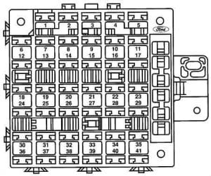
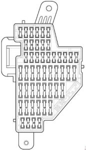
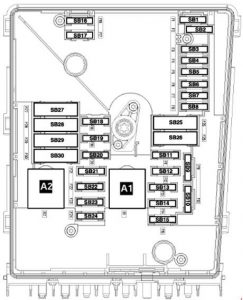
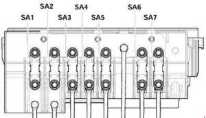
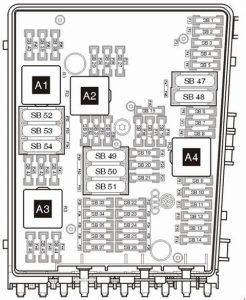
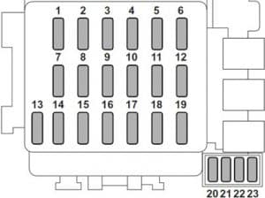
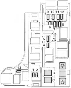
No.
|
A
|
Function/component
|
| 1 |
10 |
T16 – Diagnostic connection (T16/1)
J623 – Engine control unit
J757 – Engine component current supply relay (167) (from May 2005)
J538 – Fuel pump control unit (from May 2005)
J485 – Relay for auxiliary heater operation (from 2006)
N79 – Heater element for crankcase breather (from 2006)
G70 – Air mass meter (from 2006)
J431 – Control unit for headlight range control (from 2006) |
| 2 |
5 |
J104 – ABS control unit
E132 – Traction control system switch
E256 – TCS and ESP button
E492 – Tyre pressure monitor display button
F – Brake light switch (low; from November 2005) |
| 10 |
J623 – Engine control unit (from 2006)
V49 – Right headlight range control motor (from 006)
V48 – Left headlight range control motor (from 2006)
E102 – Headlight range control regulator (from 2006)
J538 – Fuel pump control unit (from 2006)
J345 – Trailer detector control unit (from 2006)
J587 – Selector lever sensors control unit (from 2006)
J533 – Data bus diagnostic interface (from 2006)
J285 – Control unit in dash panel insert (from 2006)
J500 – Power steering control unit (from 2006)
J104 – ABS with EDL control unit (from 2006)
E132 – Traction control system switch (from 2006)
E256 – TCS and ESP button (from 2006)
G476 – Brake pedal position sender (from 2006)
E1 – Light switch (from 2006)
F47 – Brake pedal switch, (from November 2005) |
| 3 |
10 |
J500 – Power steering control unit (up to May 2005) |
| 5 |
J234 – Airbag control unit (from May 2005) |
| 4 |
5 |
E16 – Heater/heat output switch
G65 – High-pressure sender
J131 – Heated driver seat control unit
J132 – Heated front passenger seat control unit
J255 – Climatronic control unit
K216 – Stabilisation program warning lamp 2 (from May 2005)
M17 – Reversing light bulb (from May 2005)
E422 – Tyre pressure monitor display button (from May 2005)
G266 – Oil level and oil temperature sender (high; from May 2005)
J530 – Garage door operation control unit (from May 2006)
G128 – Seat occupied sensor, front passenger side (from May 2006)
Y7 – Automatic anti-dazzle interior mirror (from May 2006)
Z20 – Left washer jet heater element (from May 2006)
Z21 – Right washer jet heater element (from May 2006) |
| 10 |
G266 – Oil level and oil temperature sender (high; from November 2005)
M17 – Reversing light (high; from November 2005)
J255 – Climatronic control unit (high; from November 2005)
G65 – High-pressure sender (high; from November 2005)
E16 – Switch for heater and heater output (high; from November 2005)
J530 – Garage door operation control unit (high; from November 2005)
N253 – Battery isolation igniter (high; from November 2005)
Y7 – Automatic anti-dazzle interior mirror (high; from November 2005)
E422 – Tyre pressure monitor display button (high; from November 2005)
K216 – Stabilisation programme warning lamp 2 (high; from November 2005)
Z20 – Left washer jet heater element (high; from November 2005)
Z21 – Right washer jet heater element (high; from November 2005)
L71 – Illumination for traction control system switch (high; from November 2005)
J301 – Air conditioning system control unit (high; from May 2007) |
| 5 |
5 |
F47 – Cruise control system brake pedal switch (to May 2005)
G476 – Clutch position sender
J431 – Control unit for headlight range control (from May 2005)
J500 – Power steering control unit (from May 2005)
J745 – Cornering light and headlight range control unit, on right headlight, (high; December 2006) |
| 10 |
J745 – Cornering light and headlight range control unit, on right headlight (low; from May 2006), (high; from May 2007) |
| 6 |
5 |
J285 – Control unit in dash panel insert (up to May 2006)
J538 – Fuel pump control unit (up to May 2006)
J533 – Data bus diagnostic interface (up to May 2006)
F125 – Multifunction switch (up to May 2006)
J587 – Selector lever sensors control unit (up to May 2006)
F189 – Tiptronic switch (up to May 2006)
J745 – Cornering light and headlight range control unit, on left of headlight (high; December 2006) |
| 10 |
J745 – Cornering light and headlight range control unit, on left headlight (low; from May 2006), (high; from May 2007) |
| 7 |
5 |
J431 – Control unit for headlight range control (to May 2005)
Y7 – Automatic anti-dazzle interior mirror (from May 2005)
Not assigned (from May 2006) |
| 8 |
5 |
Y7 – Automatic anti-dazzle interior mirror (to May 2005) |
| 10 |
J345 – Trailer detector control unit (from May 2005)
Not assigned (from May 2006) |
| 9 |
5 |
Not assigned (to May 2005)
J503 – Control unit with display for radio and navigation system (only commercial navigation system unit) (from May 2005)
Not assigned (from May 2006) |
| 10 |
5 |
J412 – Mobile telephone operating electronics control unit (to May 2005)
J530 – Garage door operation control unit (from May 2005)
J706 – Seat occupied recognition control unit (from May 2005)
Not assigned (from May 2006) |
| 11 |
5 |
J345 – Trailer detector control unit (to May 2005)
Not assigned (from May 2005) |
| 10 |
J745 – Cornering light and headlight range control unit, on right headlight, (from May 2007) |
| 12 |
10 |
J386 – Driver door control unit
J387 – Front passenger door control unit |
| 13 |
10 |
E1 – Light switch
T16 – Diagnostic connection (T16/16)
F47 – Brake pedal switch (from May 2005)
G397 – Sensor for rain and light detection (from 2006)
G197 – Magnetic field sender for compass (from 2006) |
| 14 |
5 |
F – Brake light switch (low; from May 2005)
J217 – Automatic gearbox control unit |
| 10 |
J587 – Selector lever sensors control unit (from 2006)
R149 – Remote control receiver for auxiliary coolant heater (from 2006)
J301 – Air conditioning system control unit (from 2006)
J255 – Climatronic control unit (from 2006)
E16 – Heater/heat output switch (from 2006)
J446 – Parking aid control unit (from 2006)
J104 – ABS with EDL control unit (from 2006)
E94 – Heated driver seat regulator (from 2006)
E95 – Heated front passenger seat regulator (from May 2006)
J217 – Automatic gearbox control unit (from November 2005) |
| 15 |
7.5 |
J519 – Onboard supply control unit (interior illumination) |
| 16 |
10 |
E16 – Heater/heat output switch
J301 – Air conditioning system control unit
J255 – Climatronic control unit
R149 – Remote control receiver for auxiliary coolant heater
Not assigned (from May 2006) |
| 5 |
J515 – Aerial selection control unit (high; from November 2005) |
| 17 |
5 |
G397 – Rain and light detector sensor (up to May 2006)
J515 – Aerial selection control unit (up to May 2006)
G273 – Interior monitoring sensor (from 2006)
G384 – Vehicle inclination sender (from 2006)
H12 – Alarm horn (from 2006) |
| 18 |
5 |
J446 – Parking aid control unit
J587 – Selector lever sensors control unit
Not assigned (from 2006) |
| 19 |
5 |
J754 – Accident data memory |
| 20 |
5 |
J104 – ABS with EDL control unit
Not assigned (from 2006) |
| 21 |
5 |
J503 – Control unit with display for radio and navigation system (only commercial navigation system unit) (up to May 2005)
Not assigned (from May 2005)
J542 – Control unit for engine speed governor, in front left footwell (special vehicles) (high; from May 2007)
J378 – PDA control unit (special vehicles) (from May 2007) |
| 22 |
40 |
V2 – Fresh air blower (Climatronic)
N253 – Battery isolation igniter (rear battery) (high; from May 2005) |
| 23 |
30 |
J386 – Driver door control unit (window regulator)
J387 – Front passenger door control unit (window regulator) |
| 24 |
25 |
U1 – Cigarette lighter (up to May 2006)
U9 – Rear cigarette lighter (up to May 2006)
U5 – 12 V socket (criminal investigation department) |
| 20 |
J388 – Rear left door control unit (central locking) (from 2006)
J389 – Rear right door control unit (central locking) (from 2006)
J393 – Convenience system central control unit (from 2006) |
| 25 |
J388 – Rear left door control unit (central locking) (high; from May 2007)
J389 – Rear right door control unit (central locking) (high; from May 2007)
J393 – Convenience system central control unit (high; from May 2007) |
| 25 |
25 |
Z1 – Heated rear window
J301 – Air conditioning system control unit (only with auxiliary coolant heater)
E16 – Heater/heat output switch (only with auxiliary coolant heater)
N24 – Fresh air blower series resistor (only with auxiliary coolant heater) |
| 26 |
20 |
U5 – 12 V socket (luggage compartment) (up to May 2006) |
| 30 |
J388 – Rear left door control unit (window regulator) (from May 2006)
J389 – Rear right door control unit (window regulator) (from May 2006) |
| 27 |
15 |
J538 – Fuel pump control unit
G6 – Fuel system pressurisation pump
J17 – Fuel pump control unit
J643 – Fuel supply relay (from May 2006) |
| 28 |
10 |
Charging point for Mag- Lite electric torch (special vehicle interface) (up to May 2005) |
| 30 |
U13 – Transformer with socket, 12V-230V (from May 2005)
Not assigned (from May 2006) |
| 25 |
Special vehicles socket (not for USA/Canada ) (high; from November 2005) |
| 29 |
10 |
J220/J623 – Motronic control unit
J248/J623 – Diesel direct injection system control unit
G70 – Air mass meter (AXX)
N79 – Heater element for crankcase breather (BUB, BMJ)
Not assigned (from 2006) |
| 30 |
5 |
J234 – Airbag control unit (to May 2005)
K145 – Front passenger side airbag deactivated warning lamp (to May 2005) |
| 10 |
N30 – Injector, cylinder 1 (from May 2005)
N31 – Injector, cylinder 2 (from May 2005)
N32 – Injector, cylinder 3 (from May 2005)
N33 – Injector, cylinder 4 (from May 2005) |
| 20 |
N30 – Injector, cylinder 1
N31 – Injector, cylinder 2
N32 – Injector, cylinder 3
N33 – Injector, cylinder 4
N83 – Injector, cylinder 5
N84 – Injector, cylinder 6
J217 – Automatic gearbox control unit (from 2006)
J743 – Mechatronics for direct shift gearbox (from 2006) |
| 31 |
5 |
F4 – Reversing light switch (up to May 2005)
J743 – Mechatronics for direct shift gearbox (up to May 2005) |
| 20 |
V192 – Vacuum pump for brakes (from May 2005) |
| 32 |
30 |
J388 – Rear left door control unit (window regulator) (up to May 2006)
J389 – Rear right door control unit (window regulator) (up to May 2006)
U13 – Transformer with socket, 12V-230 V (from May 2006)
U27 – Transformer with socket, 12V- 15 V, (USA/Canada) (from May 2006) |
| 33 |
25 |
J245 – Sliding sunroof adjustment control unit |
| 34 |
15 |
V125 – Driver seat lumbar support longitudinal adjustment motor
V126 – Front passenger seat lumbar support longitudinal adjustment motor
V129 – Driver seat lumbar support height adjustment motor
V130 – Front passenger seat lumbar support height adjustment motor |
| 35 |
5 |
G273 – Interior monitoring sensor
G384 – Vehicle inclination sender
H12 – Alarm horn
Not assigned (from 2006) |
| 36 |
20 |
V11 – Headlight washer system pump
J39 – Headlight washer system relay |
| 37 |
30 |
J131 – Heated driver seat control unit
J132 – Heated front passenger seat control unit |
| 38 |
10 |
J23 – Rotating light and siren system control unit (up to May 2005)
Not assigned (from May 2005)
J745 – Cornering light and headlight range control unit, on left headlight, (from May 2007) |
| 20 |
J388 – Rear left door control unit (central locking), NAR, with alarm horn relay J641) (from May 2006)
J389 – Rear right door control unit (central locking), NAR, with alarm horn relay J641) (from May 2006)
J393 – Convenience system central control unit (only VR6) (from May 2006) |
| 39 |
20 |
Not assigned (up to May 2005)
J217 – Automatic gearbox control unit (from May 2005)
Not assigned (from May 2006) |
| 40 |
40 |
E16 – Heater/heat output switch (fresh air blower)
J301 – Air conditioning system control unit (fresh air blower) |
| 5 |
E16 – Heater/heat output switch (fresh air blower) (high; from November 2005)
J301 – Air conditioning system control unit (fresh air blower) (high; from November 2005) |
| 41 |
15 |
V12 – Rear window wiper motor (up to May 2006) |
| 20 |
V12 – Rear window wiper motor (from May 2006)
J519 – Onboard supply control unit (double washer pump) (BSG J1) (from May 2006) |
| 42 |
15 |
J729 – Double washer pump relay 1 (to May 2005)
J730 – Double washer pump relay 2 (to May 2005)
J519 – Onboard supply control unit (double washer pump) (BSG J1) (from May 2005) |
| 20 |
U1 – Cigarette lighter (from May 2006)
U9 – Rear cigarette lighter (from May 2006)
U5 – 12 V socket (criminal investigation department) (from May 2006) |
| 43 |
15 |
J345 – Trailer detector control unit |
| 44 |
20 |
J345 – Trailer detector control unit |
| 45 |
15 |
J345 – Trailer detector control unit |
| 46 |
5 |
Z20 – Left washer jet heater element
Z21 – Right washer jet heater element
E94 – Heated driver seat regulator
E95 – Heated front passenger seat regulator
Not assigned (from May 2006) |
| 47 |
5 |
J485 – Auxiliary heater operation relay
Not assigned (from May 2006) |
| 48 |
10 |
Not assigned (to May 2005)
Charger for Mag-Lite and hand-held two-way radio (from May 2005) |
| 49 |
5 |
E1 – Lighting switch
Not assigned (from May 2006) |
