Honda Pilot (2003 – 2008) – fuse box diagram
Year of production: 1999, 2000, 2001, 2002, 2003, 2004, 2005, 2006, 2007, 2008, 2009
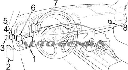
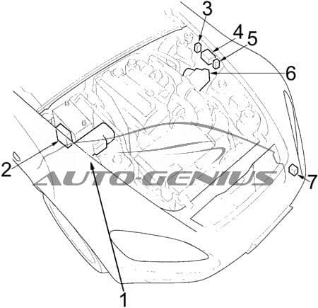
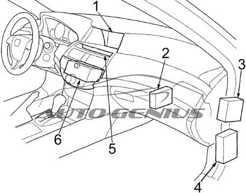
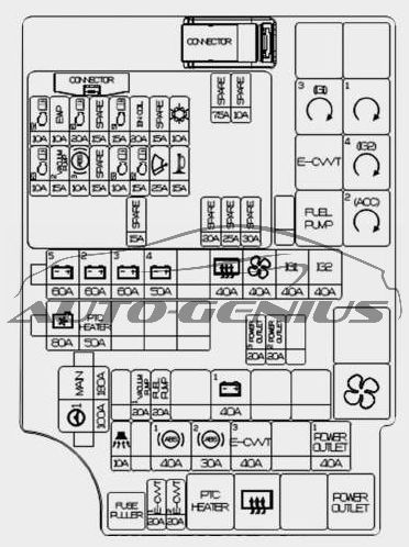
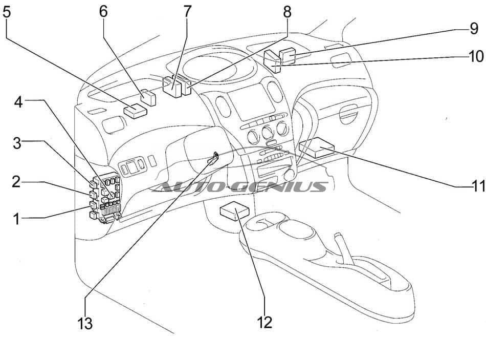
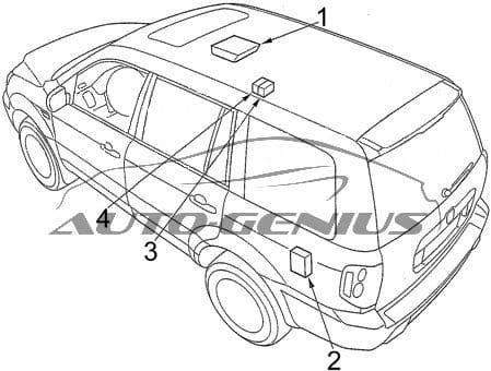
Passenger compartment
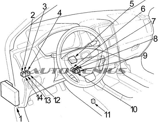
- Fuse Box No.1
- Rear Accessory Power Socket Relay
- Interior Light Relay
- ’03-’05: Front Fog Light Relay
’06-’08: Low Beam Cut Relay - Daytime Running Light Control Unit
- ’06-’08: Windshield Washer Motor Relay
- Shift Lock Relay
- P Pin Relay
- PGM-FI Main Relay No.1
- PGM-FI Main Relay No.2 (Fuel Pump)
- Rear Blower Motor Relay
- ’03-’05: Dimmer Relay
’06-’08: Daytime Running Light Relay - Taillight Relay
- 4WD: Variable Torque Management 4WD System (VTM-4) Relay
2WD (’06-’08): Engine Mount Control Relay
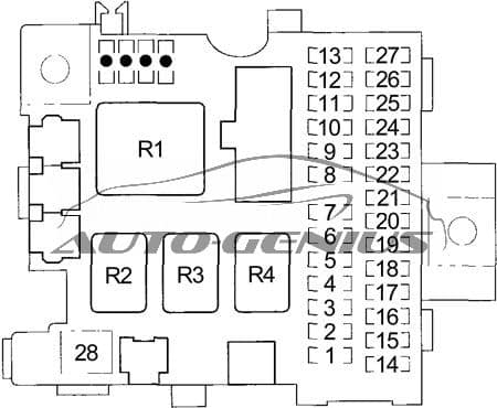
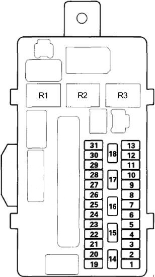
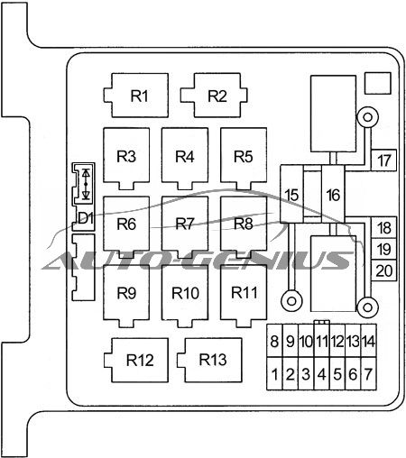
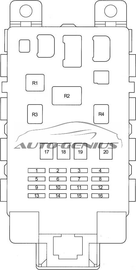
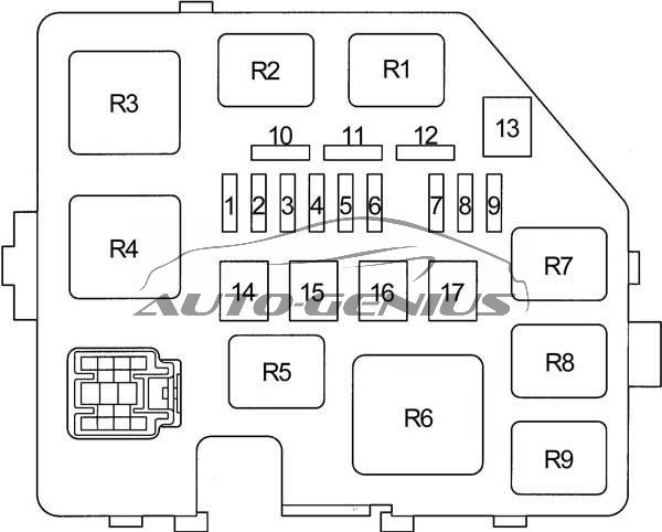
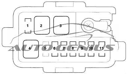
Passenger compartment fuse box no. 1
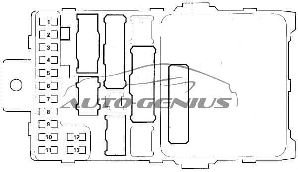
| No. | A | Circuits |
| 1 | 15 | Immobilizer Control Unit-Receiver, Powertrain Control Module (PCM), PGM-FI Main Relay No.2 (Fuel Pump), Supplemental Restraint System (SRS) Unit |
| 2 | 10 | Supplemental Restraint System (SRS) Unit |
| 3 | 7,5 | A/C Compressor Clutch Relay, Blower Motor Relay, Climate Control Unit, Heater Control Panel, Powertrain Control Module (PCM), Recirculation Control Motor, Rear Blower Motor Relay, Near Mode Motor, Rear Window Defogger Relay, Radiator Fan Control Module (’03-’05) |
| 4 | 7,5 | AC Inverter Unit (’06-’08), Power Mirror Actuator, Power Mirror Deforgger, ABS Modulator-Control Unit (’03-’05), Variable Torque Management 4WD System (VTM-4) (’03-’05) |
| 5 | 10 | Daytime Running Light Control Unit |
| 6 | 15 | Alternator, Cruise Control Main Switch Indicator Light, Evaporative Emission Control (EVAP) Canister Purge Valve, Gauge Control Module, Powertrain Control Module (PCM), VSA Modulator-Control Unit (’06-’08), Electrical Load Detector (ELD) Unit (’03-’05), Secondary Heated Oxygen Sensors (’03-’05), Radiator Fan Control Module (’03-’05), Variable Torque Management 4WD System (VTM-4) (’03-’05), VTM-4 Relay (’03-’05) |
| 7 | 7,5 | Electrical Compass Mirror (’06-’08), Occupant Detection System (ODS) Unit Passenger’s Cutoff Indicator, Automatic Dimming Inside Mirror (’06-’08), Rear Window Intermittent Wiper Relay, Rear Window Wiper/washer Switch, Rear Window Wiper Motor, Front Fog Light (’06-’08) |
| 8 | 7,5 | Accessory Power Socket Relay, Active Noise Control Rear Microphone (2WD) (’06-’08), Active Noise Control Unit (2WD) (’06-’08), Gauge Control Module, Optional Keyless Connector (’06-’08), Rear Accessory Power Socket Relay, Shift Lock Relay |
| 9 | 10 | Active Noise Control Unit (2WD) (’06-’08), A/T Reverse Relay, Back-up Lights, Brake Light Failure Sensor, Gauge Control Module, Keyless Receiver Unit, Navigation Unit (’06-’08), Automatic Dimming Inside Mirror (’06-’08), Optional Security Connector (’06-’08), Passenger’s Multiplex Control Unit, Shift Lock Solenoid (’06-’08), Variable Torque Management 4WD System (VTM-4) Lock Switch Indicator Light (4WD), Variable Torque Management 4WD System (VTM-4) Control Unit, Driver’s Multiplex Control Unit |
| 10 | 7,5 | Turn Signal/Hazard Relay |
| 11 | 7,5 | ’06-’08: Variable Torque Management 4WD System (VTM-4) Control Unit |
| 15 | ’03-’05: Ignition Coils | |
| 12 | 30 | Rear Window Washer Motor Relay, Windshield Wiper Motor, Windshield Intermittent Wiper Circuit, Windshield Washer Motor, Windshield Intermittent Wiper Relay |
| 13 | 7,5 | PGM-FI Main Relay, Powertrain Control Module (PCM) |
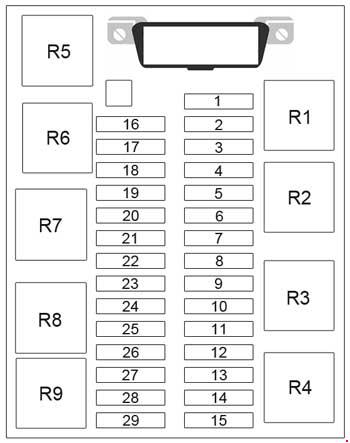
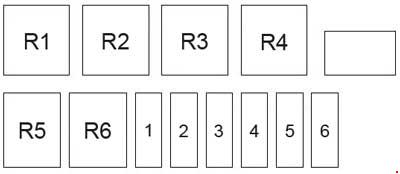
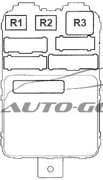
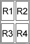
View of Back Side
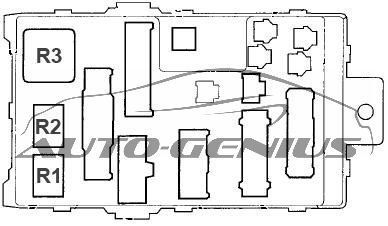
| No. | Relay |
| R1 | Starter Cut |
| R2 | Reverse |
| R3 | Turn Signal/Hazard |
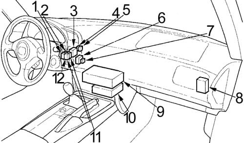
- Immobilizer Control Unit-Receiver
- 2WD (’06-’08): Active Noise Control Unit
- Keyless Receiver Unit
- Air Fuel Ratio (A/F) Sensor Relay
- Ignition Relay
- Throttle Actuator Control Module Relay
- ’06-’08: Rear Washer Motor Relay
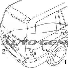
- Fuse Box No.2
- Supplemental Restraint System (SRS) Unit
- 2WD (’06-’08): Engine Mount Control Unit
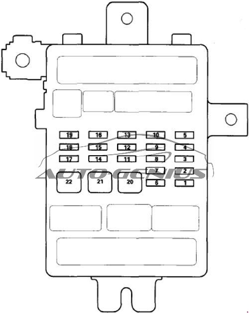
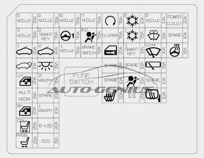
Passenger Compartment Fuse Box No.2
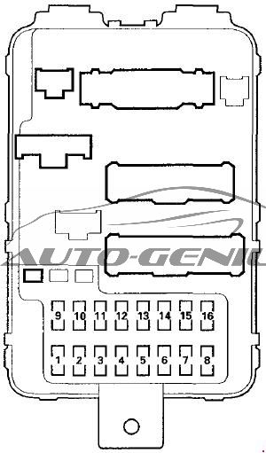
| No. | A | Circuits |
| 1 | 20 | Power Window Control Unit |
| 2 | 20 | Driver’s Power Seat Front Up-Down Motor (EX-L), Driver’s Power Seat Slide Motor (EX-L) Driver’s Power Seat Rear Up-Down Motor (Except EX-L), Driver’s Power Seat Recline Motor (Expert EX-L) |
| 3 | 20 | Front Seat Heaters |
| 4 | 20 | Driver’s Power Seat Rear Up-Down Motor (EX-L), Driver’s Power Seat Recline Motor (EX-L), Driver’s Power Seat Rear Up-Down Motor (Except EX-L), Driver’s Power Seat Slide Motor (Except EX-L) |
| 5 | — | — |
| 6 | 10 | Daytime Running Lights Control Units |
| 7 | 20 | Left Rear Window Motor, Power Window Master Switch, Power Window Control Unit |
| 8 | 20 | Front Passenger’s Window Motor |
| 9 | 15 | Audio Unit, DVD Player Unit (with Rear Entertainment System), Console Accessory Power Socket, Front Accessory Power Socket, Navigation Unit, Navigation Display Unit, Cigarette Lighter Connector |
| 10 | 15 | Audio Unit Light, Auxiliary Jack Assembly Light (with Rear Entertainment System), Cruise Control Main Switch Light, Climate Control Unit Light, DVD Player Unit (with Rear Entertainment System), Driver’s Multiplex Control Unit, Front Parking Lights, Front Side Marker Lights, Front Console Light, Front Door Lock Switches Light, Gauge Control Module Lights, Glove Box Light, Hazard Warning Switch Light, Heater Control Panel Lights, Interior Lights Switch Light, License Plate Lights, Moonroof Switch Light, Navigation Display Unit, Navigation Unit, Cigarette Lighter Connector, Fog Light Connector (driver’s Under-dash Fuse/relay Box), Power Mirror Switch Light, Rear Heater-A/C Control Unit Light, Rear Controller and Screen (with Rear Entertainment System), Roof Console Light, Seat Heater Switches Light, Taillight Relay, Taillights, Trailer Lighting Connector, VTM-4 Locks Switch Light |
| 11 | 10 | Front Individual Map Lights, Front Door Courtesy Lights, HomeLink, Interior Lights Relay, Navigation Display Unit, Navigation Unit, Rear Individual Map Lights, Tailgate Light, Vanity Mirror Lights |
| 12 | 20 | Passenger’s Multiplex Control Unit |
| 13 | 7,5 | Driver’s Multiplex Control Unit, Door Multiplex Control Unit, Gauge Control Module, Immobilizer Control Unit-Receiver, Immobilizer Indicator, Keyless Receiver Unit, Security Connector, Security Indicator, Passenger’s Multiplex Control Unit |
| 14 | 7,5 | ’06-’08: Moonroof Close Relay, Moonroof Open Relay |
| 15 | 20 | ’06-’08: Moonroof Close Relay, Moonroof Motor, Moonroof Open Relay |
| 16 | 20 | Right Rear Window Motor |
| Auxiliary Holder | ||
| 7,5 | Radiator Fan Relay | |
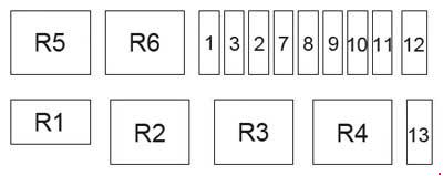
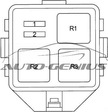
View of Back Side
| No. | Relay |
| R1 | Power Window |
| R2 | Accessory Power Socket |
| R3 | Rear Window Defogger |
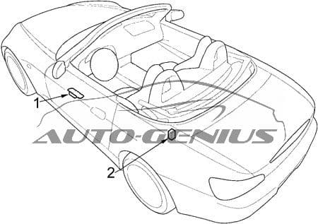
- Rear Controller and Screen (with Rear Entertainment System)
- Variable Torque Management 4WD System (VTM-4) Control Unit
- Moonroof Close Relay
- Moonroof Open Relay
- XM Receiver (XM Radio)
- Imoes Unit
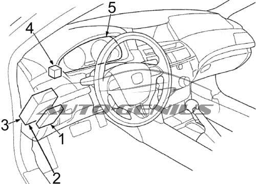
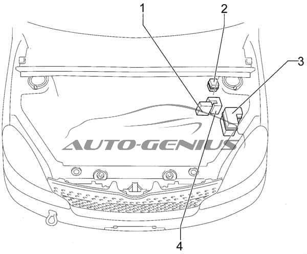
Engine Compartment
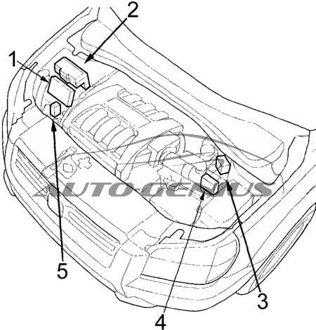
- Powertrain Control Module (PCM)
- Fuse Box No.1
- Fuse Box No.2
- ABS or VSA Modulator-Control Unit
- Relay Box
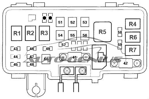
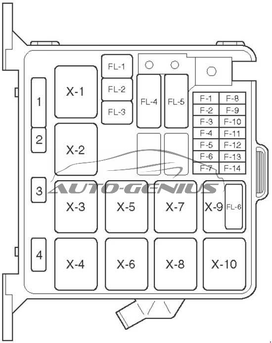
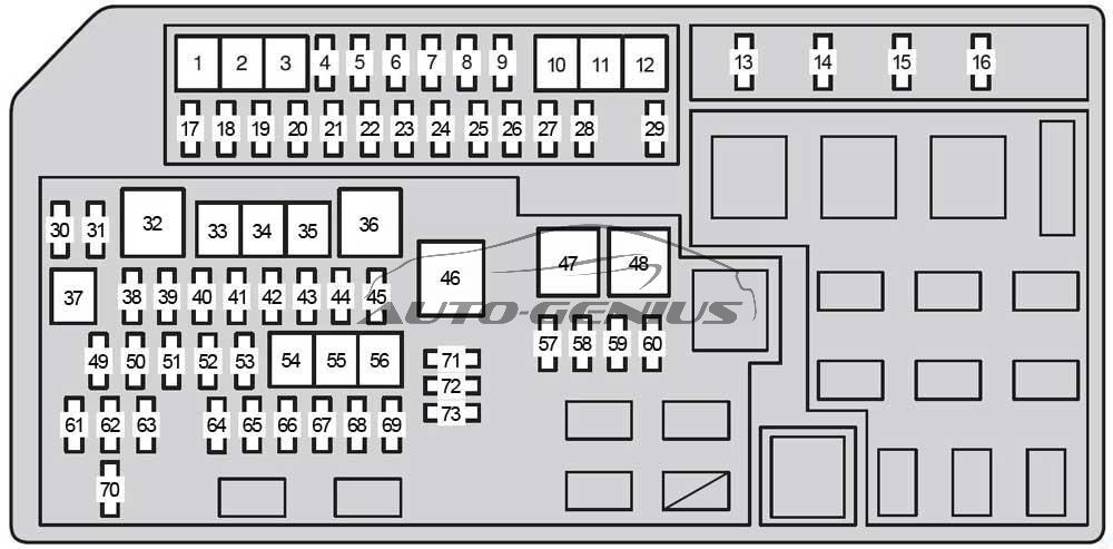
Engine compartment fuse box no.1

| No. | A | Circuits |
| 41 | 120 | Battery, Power Distribution |
| 42 | 50 | Ignition Switch, Optional Keyless Connector |
| 43 | 20 | Combination Light Switch, Daytime Running Lights Control Unit, Right Headlights |
| 44 | — | — |
| 45 | 20 | Combination Light Switch, Daytime Running Lights Control Unit, Left Headlights, High Beam Indicator Light, Fog Light (’06-’08) |
| 46 | 15 | Data Link Connector (DLC), PGM-FI Main Relay |
| 47 | 20 | Breake Lights, Drive’s Multiplex Control Unit, High Mount Brake Light, Horn Relay, Horns, Ignition Key Light, Key Interlock Solenoid, Powertrin Control Module (PCM), Trailer Lighting Connector |
| 48 | 20 | Audio Unit, DVD Player Unit (rear Entertainment System), Rear Controller And Screen (rear Entertainment System) |
| 49 | 15 | Hazard Warning Lights |
| 50 | 20 | ’03-’05: Trailer Lighting Connector |
| 51 | 40 | Power Window Relay, Fuse (Passenger Compartment Fuse Box No.2): No. 1 |
| 52 | 40 | Fuses (Passenger Compartment Fuse Box No.2): No.2, 3, 4, 6 |
| 53 | 30 | Noise Condenser, Rear Window Defogger |
| 54 | 40 | Fuse (Passenger Compartment Fuse Box No.2): No.9, 10, 11, 12, 13 |
| 55 | 30 | Rear Blower Motor |
| 56 | 40 | Blower Motor |
| 57 | 30 | Radiator Fan Motor |
| 58 | 30 | A/C Condenser Fan Motor |
| 59 | 7,5 | A/C Compressor Clutch |
| * | * | Spare Fuse |
| Relay | ||
| R1 | — | Headlight No.1 (Right) |
| R2 | — | Headlight No.2 (Left) |
| R3 | — | Horn |
| R4 | — | A/C Condenser Fan |
| R5 | — | Blower Motor |
| R6 | — | Radiator Fan |
| R7 | — | A/C Compressor Clutch |
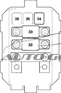
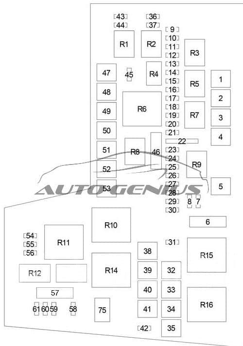
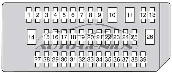
Engine compartment fuse box no. 2
| No. | A | Circuits |
| 1 | 20 | AC Inverter Unit |
| 2 | 40 | VSA Modulator-Control Unit |
| 3 | 30 | VSA Modulator-Control Unit |
| 4 | 20 | Variable Torque Management 4WD System (VTM-4) Control Unit |
| 5 | 10 | 2WD: Engine Mount Control Unit |
| 6 | 15 | Console Accessory Power Socket, Rear Accessory Power Socket |
| 7 | 15 | Powertrain Control Module (PCM) |
| 8 | 15 | Ignition Coils |
| 9 | 15 | Air Fuel Ratio (A/F) Sensors (Bank 1, Bank 2), Secondary Heated Oxygen Sensors (Bank 1, Bank 2), Electrical Load Detector (ELD) Unit |
| 10 | 7,5 | Tire Pressure Monitoring System (TPMS) Control Unit |
| 11 | 20 | Front Fog Light, Gauge Control Module, Fog Light Connector, Fog Light Switch Connector |
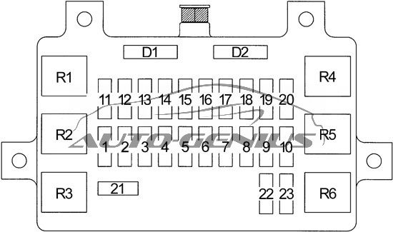
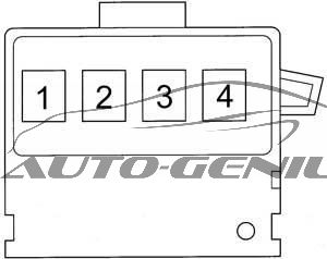
Engine Compartment Relay Box
| No. | Relay |
| R1 | Fan Control |
| R2 | Rear Window Intermittent Wiper |
| R3 | Windshield Intermittent Wiper |
| R4 | Seat Heater |
WARNING: Terminal and harness assignments for individual connectors will vary depending on vehicle equipment level, model, and market.