Cadillac Eldorado (1979 – 1981) – fuse box diagram

Cadillac Eldorado (1979 – 1981) – fuse box diagram

Year of production: 1979, 1980, 1981

Fuse box diagram

Cadillac Eldorado - fuse box diagram
Cadillac Eldorado – fuse box diagram
Fuse [A] Protected Component
1 3 Fuel injector
2 3 Fuel injector
3 3 Fuel pump cranking circuit
4 20 ECS battery
5 10 MDA ignition
6 10 Fuel pump
7 15 ECS ignition
8
 
Cadillac Eldorado - fuse box diagram
Cadillac Eldorado – fuse box diagram
Fuse [A] Protected Component
1 10 Cornering, side marker, opera, right door ash tray, instrument panel ash tray lights
2 3 Cruise control, DFI brake switch
3 5 Rheostat controlled instrument panel lights
4
5 10 Back-up lights, diesel fast idle, diesel controller
6 20 Air conditioning compressor feed, ECC programmer and power module, rear defogger relay coil, generator indicator
7 10 Antenna motor feed
8 8 Turn signal lights
9 25 Opera, license, tail and rear side marker lights
10 20 Stop light switch, hazard warning flasher, ECC control head
11 20 Fuel gauge, oil pressure and coolant temperature indicator, low brake fluid indicator, seat belt warning chime and indicator, electronic level control compressor, downshift switch
12 20 Key warning buzzer, coolant temperature indicator, instrument panel courtesy and compartment lights, cigar lighter, engine telltale light, glove box light
13 25 Automatic Temperature Control blower
14
15 10 Radio, antenna relay coil
16 20 Electronic fuel injection (’79)
17 20 Body courtesy lights, cigar lighters, level control height sensor, ash tray lights
18 25 Windshield wipers and low washer fluid indicator
19 25 Rear window defogger
Circuit Breaker:
  • Headlights (Twilight Sentinel) — Integral with headlight switch.
  • Windshield Wiper — Integral with windshield wiper switch.
  • Rear Defogger — Circuit breaker located on lower steering column cover reinforcement.
  • Sunroof — 25 amp. On body bracket at upper right corner of fuse block
Fusible Link:
  • Accessories & Body Feed — 16 gauge fusible link located in black/red stripe wire at starter
  • Ignition — 16 gauge fusible link located in red wire at starter solenoid
  • Headlights — 18 gauge fusible link located in yellow wire at starter
  • Charging — 16 gauge fusible link located in red/white stripe wire at junction block
  • Fuel Injection Electronic Control Unit – 18 gauge fusible link located in dark green wire on “BAT” terminal of alternator (’79).
In-Line Fuse:
  • Vanity Mirror — 2 amp. fuse located behind mirror
  • EFI Fuel Pump — 10 amp. fuse located left of fuel injection electronic control unit brown wire (’79)
  • Theft Deterrent — One 20 amp. fuse for lights, and one 25 amp. fuse for horn is located above radio in instrument panel.
  • Trunk Lid Pull Down — One 20 amp. fuse is located behind right hand fabric rear end panel inside trunk.
WARNING: Terminal and harness assignments for individual connectors will vary depending on vehicle equipment level, model, and market.

Cadillac Seville (1980 – 1985) – fuse box diagram

Cadillac Seville (1980 – 1985) – fuse box diagram

Year of production: 1980, 1981, 1982, 1983, 1984, 1985

Fuse box diagram

Cadillac Seville - fuse box diagram
Cadillac Seville – fuse box diagram
Fuse [A] Protected Component
1 10 Front side marker, cornering and ash tray lights
2 3 Cruise control and DFI brake switch
3 5 Rheostat controlled instrument panel lights
4
5 10 Back-up lights, diesel fast idle, diesel controller
6 20 Air conditioning compressor feed, ECC programmer and power module, rear defogger relay coil and generator indicator
7 10 Antenna motor feed
8 20 Turn signal lights
9 25 Opera, license, tail and rear side marker lights
10 20 Stop light switch, hazard warning flasher and ECC control head
11 20 Fuel gauge, oil pressure and coolant temperature indicator, low brake fluid indicator, seat belt warning chime and indicator and electronic level control compressor
12 20 Key warning buzzer, coolant temperature indicator, instrument panel courtesy and compartment lights and cigar lighter
13
14
15 10 Radio and antenna relay coil
16
17 20 Body courtesy and ash tray lights, electronic level control height sensor
18 25 Windshield wipers and low washer fluid indicator
19 25 Rear window defogger
 
Cadillac Seville - fuse box diagram
Cadillac Seville – fuse box diagram
Fuse [A] Protected Component
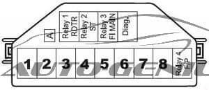
1 3 Fuel injector
2 3 Fuel injector
3 3 Fuel pump cranking circuit
4 20 ECS battery
5 10 MDA ignition
6 10 Fuel pump
7 15 ECS ignition
8

Circuit Breaker:

   Headlights (Twilight Sentinel) — Integral with headlight switch.
   Windshield Wiper — Integral with windshield wiper switch.
   Rear Defogger — Circuit breaker located on lower steering column cover reinforcement.


Fusible Link:
   All models are equipped with fusible links which attach to lower ends of main feed wires at junction block, or at starter solenoid. Gauge size is marked on insulation and each link is four sizes smaller than the cable it is designed to protect. The same size wire with special hypalon insulation must be used when replacing a fusible link.


In-Line Fuse:
   Vanity Mirror — 2 amp. fuse located behind mirror.
   Theft Deterrent – One 20 amp. fuse for lights, and one 25 amp. fuse for horn is located above radio in instrument panel.
   Trunk Lid Pull Down — One 20 amp. fuse is located behind right hand fabric rear end panel inside trunk.

WARNING: Terminal and harness assignments for individual connectors will vary depending on vehicle equipment level, model, and market.

Buick Skylark (1980 – 1985) – fuse box diagram

Buick Skylark (1980 – 1985) – fuse box diagram

Year of production: 1980, 1981, 1982, 1983, 1984, 1985

Fuse box diagram

Buick Skylark - fuse box diagram
Buick Skylark – fuse box diagram
Fuse [A] Protected Component
1 5 Instrument panel, lights on reminder and console light
2 20 Choke heater and cooling fan
3
4 30 Circuit breaker: Power windows
5
6 25 Air conditioning blower and compressor, heater and trunk release
7 10 Electronic Control Module
8
9
10 20 Stop and hazard lights
11 20 Air conditioning, defogger, seat belt warning, charge indicator and computer command control
12 20 Front parking and marker lights. Rear parking, marker and license lights
13
14 30 Circuit breaker: Defogger, power door locks and power seats
15 20 Back-up and turn signal lights, and Idle stop solenoid
16 20 Air conditioning, cigar lighter, clock, courtesy, trunk and vanity lights, ignition key warning buzzer, lights on reminder, power antenna, power door locks and radio capacitor
17
18 10 Radio, cruise control and power antenna
19 25 Windshield wiper/washer and wiper/washer delay
Circuit Breaker: Headlight Circuit — A thermo circuit breaker is incorporated in the headlight switch assembly to protect headlight circuits. Windshield Wiper — Integral with windshield wiper motor.
WARNING: Terminal and harness assignments for individual connectors will vary depending on vehicle equipment level, model, and market.

Buick LeSabre (1977 – 1981) – fuse box diagram

Buick LeSabre (1977 – 1981) – fuse box diagram

Year of production: 1977, 1978, 1979, 1980, 1981, 1982, 1983

Fuse box diagram

Buick LeSabre - fuse box diagram
Buick LeSabre – fuse box diagram
Fuse [A] Protected Component
1 5 Instrument illumination, headlight warning and electronic air conditioning
2 20 Electric choke
3 5 Instrument illumination, headlight warning
4 30 Circuit breaker: Power windows and roof, fuel cap lock release
5
6 25 Heater, air conditioning, trunk lid release, radio capacitor
7 10 Electronic Control Module
8 10 Diesel engine fuse
9 25 Windshield wiper and washer
10 20 Stop and hazard lights
11 20 Seat belt light and buzzer, trunk ajar, transmission downshift and C-4 or E.S.C. jumper, heated back light relay, map and fuel economy lights, instrument gauges and indicator lights
12 20 Tail, side markers, parking, cornering and license lights, clock radio
13 10 Radio, cruise control
14 30 Circuit breaker: Power seats, door locks, heated rear window feed
15 20 Turn signals and back-up lights
16 20 Cigar lighter, glove box light, speed and key warning buzzer, power antenna, clock radio, clock, pulse wiper, air conditioning
17 20 Dome and sail panel lights, trunk light, reading light, vanity light, headlight on warning, automatic door locks and rear cigar lighter, tailgate ajar
18
19 10 Instrument gauges, indicator lights, transmission converter clutch and cruise control
19 20 Electric choke
Circuit Breaker: Headlight Circuit — A thermo circuit breaker is incorporated in the headlight switch assembly to protect headlight circuits. Windshield Wiper — Integral with windshield wiper motor.
WARNING: Terminal and harness assignments for individual connectors will vary depending on vehicle equipment level, model, and market.

Buick Riviera (1979 – 1985) – fuse box diagram

Buick Riviera (1979 – 1985) – fuse box diagram

Year of production: 1979, 1980, 1981, 1982, 1983, 1984, 1985

Fuse box diagram

Buick Riviera - fuse box diagram
Buick Riviera – fuse box diagram
Fuse [A] Protected Component
1 5 Instrument illumination, headlight warning and electronic air conditioning
2 20 Electric choke
3 5 Instrument illumination, headlight warning
4 30 Circuit breaker: Power windows and roof, fuel cap lock release
5
6 25 Heater, air conditioning, trunk lid release, radio capacitor
7 10 Electronic Control Module
8 10 Diesel engine fuse
9 25 Windshield wiper and washer
10 20 Stop and hazard lights
11 20 Seat belt light and buzzer, trunk ajar, C-4 system or turbo controller, heated back light relay, map and fuel economy lights, instrument gauges and indicator lights
12 20 Tail, side markers, parking, cornering and license lights, clock radio
13 10 Radio, cruise control
14 30 Circuit breaker: Power seats, door locks, heated rear window feed
15 20 Turn signals and back-up lights, automatic door lock and idle stop relay
16 20 Cigar lighter, glove box light, speed and key warning buzzer, power antenna, clock radio, clock, pulse wiper, air conditioning
17 20 Dome and sail panel lights, trunk light, reading light, vanity light, headlight on warning, automatic door locks and rear cigar lighter
18
19 20 Automatic level control compression
19 20 Electric choke
Circuit Breaker: Headlight Circuit — A thermo circuit breaker is incorporated in the headlight switch assembly to protect headlight circuits. Windshield Wiper — Integral with windshield wiper motor.
WARNING: Terminal and harness assignments for individual connectors will vary depending on vehicle equipment level, model, and market.

Nissan Quest (1998 – 2002) – fuse box diagram

Nissan Quest (1998 – 2002) – fuse box diagram

Year of production: 1998, 1999, 2000, 2001

Passenger compartment

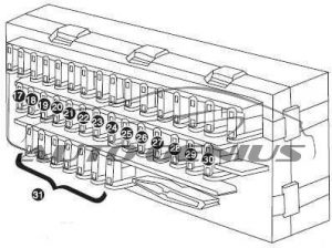
Nissan Quest - fuse box diagram - passenger compartment
Nissan Quest – fuse box diagram – passenger compartment

Passenger Compartment Fuse Box

Nissan Quest - fuse box diagram - passenger compartment fuse box
Nissan Quest – fuse box diagram – passenger compartment fuse box
Fuse [A] Protected Component
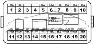
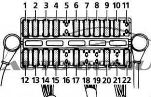
1 7,5 Front Heated Seats
2 10 Transmission Control Module (TCM), Rear Wiper Motor, EATC Unit
3 10 Air Bag Diagnosis Sensor Unit
4 10 IACV-AAC Valve, Vacuum Cut Valve Bypass Valve, Engine Control Module (ECM), Data Link Connector, Map/Baro Switch Solenoid Valve, Throttle Position Sensor, EVAP Canister Vent Control Valve
5 7,5 Door Mirror Remote Control Switch, SECU
6 20 Cigarette Lighter
7 20 Rear Power Point
8 20 Front Wiper Motor, Front Washer Motor, Front Wiper Amplifier
9 10 Rear Wiper Motor, Rear Washer Motor
10 15 ’01-’02: Audio, Video Monitor, Subwoofer Amplifier
7,5 ’98-’00: Audio
11 20 ’01-’02: Rear Power Point (Console Mounted)
20 ’98-’00: Subwoofer Amplifier
12 7,5 Headlamp Control Unit, Engine Control Module (ECM)
13 7,5 Air Conditioner Control Unit, Air Conditioner Relay, EATC Unit, Air Mix and Mode Door, IACC-FICD Solenoid Valve
14 20 Rear Window Defogger
15 20 Rear Window Defogger
16 10 Rear Window Defogger Switch, Mirror Heaters
17 10 Front Side Marker Lamps, Front Combination Lamp, Combination Switch
18 7,5 Illumination Lamps
19 10 Rear Combination Lamp, Trailer License Lamp
20 10 Audio, CD Changer, Rear Audio Remote Control Unit, FES Control Panel
21 15 Interior Lamps, Memory Seat and Mirror Control Unit, Sunroof Motor
22 20 Stop Lamp Switch, Trailer Tow Control Unit
23 10 Hazard Switch, Security Indicator Lamp
24 15 Rear Blower Motor
25 15 Rear Blower Motor
26 7,5 Heated Oxygen Sensor
27 10 Hazard Switch
28 20 Front Blower Motor, Front Blower Speed Control Unit
29 10 Data Link Connector, Combination Meter, ASCD Brake Switch, Air Conditioner Relay, Cooling Fan Relay, Rear Blower Motor Relay, Memory Seat and Mirror Control Unit, ASCD Control Unit
30 10 ABS Actuator and Electric Unit, Park/Neutral Position Switch, Headlamp Control Unit, SECU, Transmission Control Module (TCM)
31 20 Front Blower Motor, Front Blower Speed Control Unit
32
Relay
R1 Tail Lamp
R2 Ignition
R3 Accessory
R4 Rear Window Defogger
R5 Blower

Engine Compartment Fuse Box

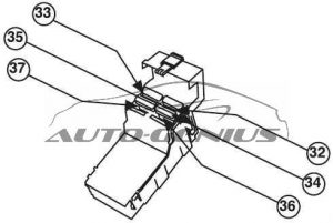
Nissan Quest - fuse box diagram - engine compartment fuse box
Nissan Quest – fuse box diagram – engine compartment fuse box
Fuse [A] Protected Component
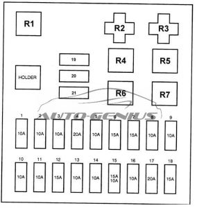
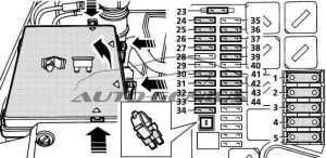
33 10 Injectors, Engine Control Module (ECM)
34 10 Engine Control Module (ECM) Relay, Data Link Connector
35 10 Generator
36 15 Headlamp RH
37 15 Headlamp LH
38 7,5 Front Fog Lamp Relay
39 7,5 SECU, Vehicle Security Relay
40
41 20 ABS Solenoid Valve Relay
42 15 Horn Relay
43 15 Fuel Pump Relay
44 7,5 Radiator Fan Sensing
45
46
47
A 100 Ignition Relay (Fuse: “26”, “27”, “29”, “30”), Accessory Relay (Fuse: “5”, “6”, “7”, “8”, “9”), Tail Lmap Relay (Fuse: “17”, “18”, “19”) Fuse: “2”, “20”, “21”, “22”, “23”
B 140 Generator, Fuse: “A”, “C”, “F”, “G”, “38”, “39”, “41”, “42”
C 65 Front Blower Motor Relay (Fuse: “28”, “31”)
D
E
F 30 Circuit Breaker 1 (SECU, Power Window Relay), Circuit Breaker 2 (Power Seat)
G 40 ABS Motor Relay
H
I 45 Rear Window Defogger Relay (Fuse: “14”, “15”, “16”), Fuse: “24”, “25”
J 75 Cooling Fan Relay
K 30 Ignition Switch
L 20 Cooling Fan Relay
M
N
Relay
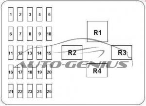
R1 Cooling Fan Relay 1
R2 Cooling Fan Relay 2
R3 Cooling Fan Relay 3

Engine Compartment Relay Box

Nissan Quest - fuse box diagram - engine compartment relay box
Nissan Quest – fuse box diagram – engine compartment relay box
Relay Description
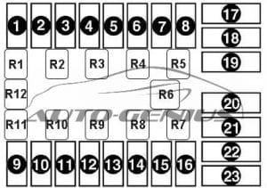
R1 Park/Neutral Position
R2 Fuel Pump
R3 Bulb Check
R4 ’01-’02: Fog Lamp
’98-’00: ASCD Hold
R5 Vehicle Security
R6 Horn
R7 Air Conditioner
WARNING: Terminal and harness assignments for individual connectors will vary depending on vehicle equipment level, model, and market.

Ford Maverick (1971 – 1977) – fuse box diagram

Ford Maverick (1971 – 1977) – fuse box diagram

Year of production: 1971, 1972, 1973, 1974, 1975, 1976, 1977

Fuse box diagram

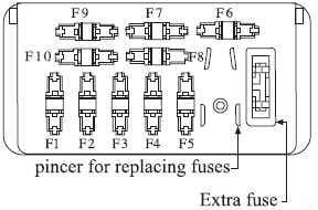
Ford Maverick - fuse box diagram
Ford Maverick – fuse box diagram
Fuse [A] Protected Component
1 20 Hazard warning flasher, cigar lighter, clock feed
2 14 Courtesy, dome, luggage compartment lights, ignition key warning buzzer
3 4 Instrument panel and cluster lights, radio, clock, shift quadrant indicator illumination lights
4 14 Indicator lights, throttle positioner, emission control solenoid, seat belt warning buzzer and light
5 14 Heater and defroster
30 Air conditioner
6 15 Back-up lights, radio feed and windshield
7 20 Accessory feed, rear window defogge
Circuit Breaker:
  • 18 A – Located integral with headlight switch; protects headlights.
  • 5 A – located integral with headlight switch; protects horn, stop, front and rear marker, front parking, rear and license lights.
  • 8 A – Located integral with windshield wiper switch; protects wiper motor circuits
WARNING: Terminal and harness assignments for individual connectors will vary depending on vehicle equipment level, model, and market.

Mercury Comet (1971 – 1977) – fuse box diagram

Mercury Comet (1971 – 1977) – fuse box diagram

Year of production: 1971, 1972, 1973, 1974, 1975, 1976, 1977

Fuse box diagram

Mercury Comet - fuse box diagram
Mercury Comet – fuse box diagram
Fuse [A] Protected Component
1 20 Hazard warning flasher, cigar lighter, clock feed
2 14 Courtesy, dome, luggage compartment lights, ignition key warning buzzer
3 4 Instrument panel and cluster lights, radio, clock, shift quadrant indicator illumination lights
4 14 Indicator lights, throttle positioner, emission control solenoid, seat belt warning buzzer and light
5 14 Heater and defroster
30 Air conditioner
6 15 Back-up lights, radio feed and windshield
7 20 Accessory feed, rear window defogge
Circuit Breaker:
  • 18 A – Located integral with headlight switch; protects headlights.
  • 5 A – located integral with headlight switch; protects horn, stop, front and rear marker, front parking, rear and license lights.
  • 8 A – Located integral with windshield wiper switch; protects wiper motor circuits
WARNING: Terminal and harness assignments for individual connectors will vary depending on vehicle equipment level, model, and market.

Buick Estate Wagon (1977 – 1984) – fuse box diagram

Buick Estate Wagon (1977 – 1984) – fuse box diagram

Year of production: 1977, 1978, 1979, 1980, 1981, 1982, 1983, 1984

Fuse box diagram

Buick Estate Wagon - fuse box diagram
Buick Estate Wagon – fuse box diagram
Fuse [A] Protected Component
1 5 Instrument illumination, headlight warning and electronic air conditioning
2 20 Electric choke
3 5 Instrument illumination, headlight warning
4 30 Circuit breaker: Power windows and roof, fuel cap lock release
5
6 25 Heater, air conditioning, trunk lid release, radio capacitor
7 10 Electronic Control Module
8 10 Diesel engine fuse
9 25 Windshield wiper and washer
10 20 Hazard and stop lights
11 20 Seat belt light and buzzer, trunk ajar, transmission downshift and C-4 or E.S.C. jumper, heated back light relay, map and fuel economy lights, instrument gauges and indicator lights
12 20 Tail, side marker, parking and license lights, clock radio
13 10 Radio, cruise control
14 30 Circuit breaker: Power seats, door locks, heated rear window feed, tailgate window
15 20 Turn signal and back-up lights
16 20 Cigar lighter, glove box light, speed and key warning buzzer, power antenna, clock radio, clock, pulse wiper, air conditioning
17 20 Dome and sail panel lights, trunk light, reading light, vanity light, headlight on warning, automatic door locks and rear cigar lighter, tailgate ajar
18
19 10 Instrument gauges, indicator lights, transmission converter clutch and cruise control, Electric choke
Circuit Breaker: Headlight Circuit — A thermo circuit breaker is incorporated in the headlight switch assembly to protect headlight circuits. Windshield Wiper — Integral with windshield wiper motor.
WARNING: Terminal and harness assignments for individual connectors will vary depending on vehicle equipment level, model, and market.

Buick Electra (1977 – 1984) – fuse box diagram

Buick Electra (1977 – 1984) – fuse box diagram

Year of production: 1977, 1978, 1979, 1980, 1981, 1982, 1983, 1984

Fuse box diagram

Buick Electra - fuse box diagram
Buick Electra – fuse box diagram
Fuse [A] Protected Component
1 5 Instrument illumination, headlight warning and electronic air conditioning
2 20 Electric choke
3 5 Instrument illumination, headlight warning
4 30 Circuit breaker: Power windows and roof, fuel cap lock release
5
6 25 Heater, air conditioning, trunk lid release, radio capacitor
7 10 Electronic Control Module
8 10 Diesel engine fuse
9 25 Windshield wiper and washer
10 20 Hazard and stop lights
11 20 Seat belt light and buzzer, trunk ajar, transmission downshift and C-4 or E.S.C. jumper, heated back light relay, map and fuel economy lights, instrument gauges and indicator lights
12 20 Tail, side marker, parking and license lights, clock radio
13 10 Radio, cruise control
14 30 Circuit breaker: Power seats, door locks, heated rear window feed, tailgate window
15 20 Turn signal and back-up lights
16 20 Cigar lighter, glove box light, speed and key warning buzzer, power antenna, clock radio, clock, pulse wiper, air conditioning
17 20 Dome and sail panel lights, trunk light, reading light, vanity light, headlight on warning, automatic door locks and rear cigar lighter, tailgate ajar
18
19 10 Instrument gauges, indicator lights, transmission converter clutch and cruise control, Electric choke
Circuit Breaker: Headlight Circuit — A thermo circuit breaker is incorporated in the headlight switch assembly to protect headlight circuits. Windshield Wiper — Integral with windshield wiper motor.
WARNING: Terminal and harness assignments for individual connectors will vary depending on vehicle equipment level, model, and market.