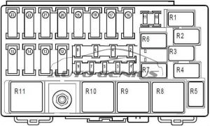
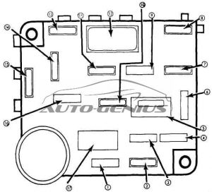
Buick Century (1978 – 1981) – fuse box diagram

Buick Century (1978 – 1981) – fuse box diagram

Year of production: 1978, 1979, 1980, 1981

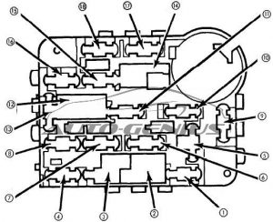
Fuse box diagram

Buick Century - fuse box diagram
Buick Century – fuse box diagram
Fuse [A] Protected Component
1 5 Instrument illumination and headlight warning
2 20 Electric choke (V6), closed loop
3
4 30 Circuit breaker: Power windows and roof
5
6 25 Heater, air conditioning, pulse wipers and deck lid
7 10 Electronic Control Module
8
9 25 Windshield wiper and washer
10 20 Hazard and stop lights
11 20 Seat belt light and buzzer, heated back light relay, tailgate window release, map light and fuel economy light
12 20 Tail, side marker, parking and license lights, clock radio
13 10 Radio
14 30 Circuit breaker: Power seats, door locks and heated back light
15 20 Turn signal and back-up lights
16 20 Clock, cigar lighter, glove box light, key buzzer, power antenna, clock radio, radio capacitor, dome and sail panel lights, trunk light, reading light, headlight on warning and door locks
17
18
19 10 Gauges, cruise control, torque converter clutch and indicator light
Circuit Breaker: Headlight Circuit — A thermo circuit breaker is incorporated in the headlight switch assembly to protect headlight circuits. Windshield Wiper — Integral with windshield wiper motor.
WARNING: Terminal and harness assignments for individual connectors will vary depending on vehicle equipment level, model, and market.

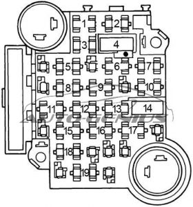
Buick Regal (1978 – 1981) – fuse box diagram

Buick Regal (1978 – 1981) – fuse box diagram

Year of production: 1978, 1979, 1980, 1981

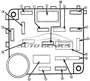
Fuse box diagram

Buick Regal - fuse box diagram
Buick Regal – fuse box diagram
Fuse [A] Protected Component
1 5 Instrument illumination and headlight warning
2 20 Electric choke (V6), closed loop
3 5 Instrument illumination and headlight warning
4 30 Circuit breaker: Power windows and roof
5
6 25 Heater, air conditioning, pulse wipers and deck lid
7 10 Electronic Control Module
8
9 25 Windshield wiper and washer
10 20 Hazard and stop lights
11 20 Seat belt light and buzzer, heated back light relay, tailgate window release, map light and fuel economy light, cruise control, rear defogger blower, instrument gauges and indicator lights, electric choke
12 20 Tail, side marker, parking and license lights, clock radio
13 10 Radio
14 30 Circuit breaker: Power seats, door locks and heated back light
15 20 Turn signal and back-up lights
16 20 Clock, cigar lighter, glove box light, key buzzer, power antenna, clock radio, radio capacitor, dome and sail panel lights, trunk light, reading light, headlight on warning and door locks
17
18
19 10 Gauges, cruise control, torque converter clutch and indicator light
Circuit Breaker: Headlight Circuit — A thermo circuit breaker is incorporated in the headlight switch assembly to protect headlight circuits. Windshield Wiper — Integral with windshield wiper motor.
WARNING: Terminal and harness assignments for individual connectors will vary depending on vehicle equipment level, model, and market.
Plymouth Fury (1974 – 1976) – fuse box diagram

Plymouth Fury (1974 – 1976) – fuse box diagram

Year of production: 1974, 1975, 1976

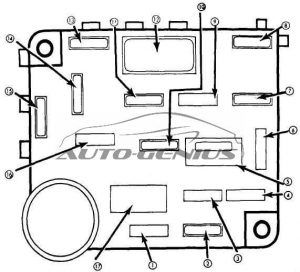
Fuse box diagram

Plymouth Fury - fuse box diagram
Plymouth Fury – fuse box diagram
Fuse [A] Protected Component
1 5 Radio
2 20 Air conditioner compressor clutch, rear window defogger, cornering lights (Monaco only), speed control, automatic temperature control relay
3 20 Turn signal flasher circuit, back-up lights, voltage limiter, fuel gauge, oil gauge, temperature gauge
4 20 Air conditioner blower motor relay, heater blower motor
5 30 Air conditioner high blower
6 5 Headlights and windshield wiper/washer switch light, instrument cluster lights (also in cavity 2), tailgate unlock switch light, radio light, rear window defogger, cigar lighter light, clock light, right ash tray light, (D-C only)
7 20 Clock, cigar lighter, tail light, side marker lights, park & turn signal lights, instrument cluster lights (also in cavity 1), license lights
8 20 Trunk light, ignition switch light & time delay relay, rear dome light (wagons only), hazard flasher circuit, stop light, seat belt, key-in headlights-on buzzer, map light, courtesy light, glove box light, dome light, seat belt light
9 20 Horns, horn relay
10 20 Power window relay, brake warning light, hot temperature indicator light (engine), door ajar indicator light, oil warning light, electric trunk, lid, seat belt interlock, ignition feed
WARNING: Terminal and harness assignments for individual connectors will vary depending on vehicle equipment level, model, and market.
Dodge Monaco (1974 – 1976) – fuse box diagram

Dodge Monaco (1974 – 1976) – fuse box diagram

Year of production: 1974, 1975, 1976

Fuse box diagram

Dodge Monaco - fuse box diagram
Dodge Monaco – fuse box diagram
Fuse [A] Protected Component
1 5 Radio
2 20 Air conditioner compressor clutch, rear window defogger, cornering lights (Monaco only), speed control, automatic temperature control relay
3 20 Turn signal flasher circuit, back-up lights, voltage limiter, fuel gauge, oil gauge, temperature gauge
4 20 Air conditioner blower motor relay, heater blower motor
5 30 Air conditioner high blower
6 5 Headlights and windshield wiper/washer switch light, instrument cluster lights (also in cavity 2), tailgate unlock switch light, radio light, rear window defogger, cigar lighter light, clock light, right ash tray light, (D-C only)
7 20 Clock, cigar lighter, tail light, side marker lights, park & turn signal lights, instrument cluster lights (also in cavity 1), license lights
8 20 Trunk light, ignition switch light & time delay relay, rear dome light (wagons only), hazard flasher circuit, stop light, seat belt, key-in headlights-on buzzer, map light, courtesy light, glove box light, dome light, seat belt light
9 20 Horns, horn relay
10 20 Power window relay, brake warning light, hot temperature indicator light (engine), door ajar indicator light, oil warning light, electric trunk, lid, seat belt interlock, ignition feed
WARNING: Terminal and harness assignments for individual connectors will vary depending on vehicle equipment level, model, and market.
Mercury Marquis (1975 – 1978) – fuse box diagram

Mercury Marquis (1975 – 1978) – fuse box diagram

Year of production: 1975, 1976, 1977, 1978

Fuse box diagram

Mercury Marquis – fuse box diagram
Fuse [A] Description
1 7,5 Indicator lights — engine hot, oil pressure, throttle positioner, dual brake, seat belt, parking brake, sure track system
2 15 Radio, power antenna
3 20 Windshield washer, heated backlite, relay coil feed, power window relay coil feed, police accessory relay coil feed, cornering lamps, intrusion alarm system, rear door cigar lighters, deck lid release, defogger, speed control system, sure-track system
4 25 Windshield wiper system
5 20 Circuit Breaker: Station wagon tailgate window
6 4 Instrument panel and cluster illumination, clock, radio, ash tray, headlight and windshield wiper switch, heater-air conditioner, ATC control
7 20 Back-up lights, turn signals, air conditioner clutch
8 15 Heater
8 30 Air conditioner
9 15 Courtesy lamps, instrument panel, door, dome, glove box, cargo (station wagon only), & luggage compartment lights, clock feed, door lock solenoid, key warning buzzer, seat back latch relay control, anti-theft system, lighted visor vanity
10 15 Hazard warning system and stop lights
11 15 Cigar Lighter
Circuit Breaker:
  • 18 Amp. — Located intergral with headlight switch; protects headlight circuits.
  • 15 Amp. — Located integral with headlight switch; protects parking lights, marker lights, license lights, tail lights, horns, trailer towing, tail light relay.
  • 20 Amp. — Located on starter relay; protects power windows, door locks, power seat, seat back latch solenoid feed.
Fuse:
  • 30 Amp. — Located in-line near relay; protects heated rear window.
  • 3 Amp. — Located in-line near fuse block, protects sure-track brake
Fuse Link — Located in harness near fuse block; protects engine compartment light, heated rear window, trailer towing (brake), trailer towing lights load circuit.

WARNING: Terminal and harness assignments for individual connectors will vary depending on vehicle equipment level, model, and market.
Ford LTD (1975 – 1978) – fuse box diagram

Ford LTD (1975 – 1978) – fuse box diagram

Year of production: 1975, 1976, 1977, 1978

Fuse box diagram

Ford LTD - fuse box diagram
Ford LTD – fuse box diagram
Fuse [A] Description
1 7,5 Indicator lights — engine hot, oil pressure, throttle positioner, dual brake, seat belt, parking brake, sure track system
2 15 Radio, power antenna
3 20 Windshield washer, heated backlite, relay coil feed, power window relay coil feed, police accessory relay coil feed, cornering lamps, intrusion alarm system, rear door cigar lighters, deck lid release, defogger, speed control system, sure-track system
4 25 Windshield wiper system
5 20 Circuit Breaker: Station wagon tailgate window
6 4 Instrument panel and cluster illumination, clock, radio, ash tray, headlight and windshield wiper switch, heater-air conditioner, ATC control
7 20 Back-up lights, turn signals, air conditioner clutch
8 15 Heater
8 30 Air conditioner
9 15 Courtesy lamps, instrument panel, door, dome, glove box, cargo (station wagon only), & luggage compartment lights, clock feed, door lock solenoid, key warning buzzer, seat back latch relay control, anti-theft system, lighted visor vanity
10 15 Hazard warning system and stop lights
11 15 Cigar Lighter
Circuit Breaker:
  • 18 Amp. — Located intergral with headlight switch; protects headlight circuits.
  • 15 Amp. — Located integral with headlight switch; protects parking lights, marker lights, license lights, tail lights, horns, trailer towing, tail light relay.
  • 20 Amp. — Located on starter relay; protects power windows, door locks, power seat, seat back latch solenoid feed.
Fuse:
  • 30 Amp. — Located in-line near relay; protects heated rear window.
  • 3 Amp. — Located in-line near fuse block
Fuse Link — Located in harness near fuse block; protects engine compartment light, heated rear window, trailer towing (brake), trailer towing lights load circuit.

WARNING: Terminal and harness assignments for individual connectors will vary depending on vehicle equipment level, model, and market.
Jayco Camping Trailer Designer CT (2003) – fuse box diagram

Jayco Camping Trailer Designer CT (2003) – fuse box diagram

Year of production: 2003

Table of fuse

Operation Location Circuit number [A] Type
Interior lights, Water pump, Radio in converter 1 15 Blade
Refrigerator in converter 2 15 Blade
Fumace in converter 3 20 Blade
Battery Pac (exterior) in line by battery 4 20 Blade
LP Detector behind LP N/A 1 Blade
WARNING: Terminal and harness assignments for individual connectors will vary depending on vehicle equipment level, model, and market.
Jayco Camping Trailer Eagel CT (2003) – fuse box diagram

Jayco Camping Trailer Eagel CT (2003) – fuse box diagram

Year of production: 2003

Table of fuse

Operation Location Circuit number [A] Type
Interior lights, Water pump, Radio in converter 1 15 Blade
Refrigerator in converter 2 15 Blade
Fumace in converter 3 20 Blade
Battery Pac (exterior) in line by battery 4 20 Blade
LP Detector behind LP N/A 1 Blade
WARNING: Terminal and harness assignments for individual connectors will vary depending on vehicle equipment level, model, and market.
Jayco Camping Trailer Qwest CT (2003) – fuse box diagram

Jayco Camping Trailer Qwest CT (2003) – fuse box diagram

Year of production: 2003

Table of fuse

Operation Location Circuit number [A] Type
Interior lights, Water pump in converter 1 15 Blade
Refrigerator in converter 2 15 Blade
Fumace in converter 3 20 Blade
Battery Pac (exterior) in line by battery 4 20 Blade
LP Detector behind LP N/A 1 Blade
WARNING: Terminal and harness assignments for individual connectors will vary depending on vehicle equipment level, model, and market.
Citroen CX (1974 – 1975) – fuse box diagram

Citroen CX (1975 – 1975) – fuse box diagram

Year of production: 1974, 1975

Table of fuse

Current supply Fuse Color Equipment protected
Window operation control relay 16 White Right-hand switch –> Right-hand window winder Left-hand switch –> Left-hand window winder
Heating relay 16 Mauve Heating unit
Positive battery terminal “+” 16 Red Stoplamps, accessory terminal, glove box lamp Lighting switch (direction indictors, instrument panel, windscreen wiper, horns, heating relay (coil), window winder relay (coil))
Positive battery terminal “+” 16 Green Interior lamp, boot lamp, cigar lighter, clock, hazard warning lamp Lighting switch (voltage regulator, reversing lamps, rear window heater)
Lighting switch 10 Yellow Ash-tray lighting, Lighting for cigar lighter, Heating control lighting, dashboard lighting, side and tail lamp warning lamp, left-hand a sidelamps and rea lamps
  10 Blue Right-hand sidelamps and rear lamps, numer plate lamp

WARNING: Terminal and harness assignments for individual connectors will vary depending on vehicle equipment level, model, and market.