Plymouth Reliant (1981 – 1984) – fuse box diagram
Year of production: 1981, 1982, 1983, 1984
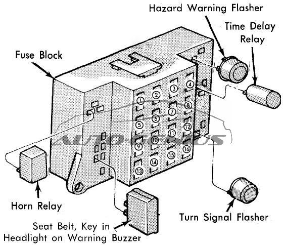
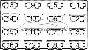
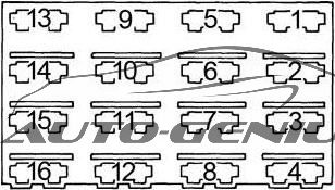
Fuse box diagram

| № |
A |
Protected Component |
| 1 | 20 | Hazard warning flashers |
| 2 | 5 | Speed control and heated rear window relay |
| 3 | 30 | Air conditioning radiator tan motor |
| 4 | 20 | Heater blower motor |
| 30 | Air conditioning blower motor | |
| 5 | 20 | Parking, tail, side marker, license, cluster and clock intensity lights |
| 6 | 20 | Stop, dome, trunk, cargo and ignition switch lights. Headlight/key warning buzzer and time delay relay |
| 7 | 20 | Glove box light, horn, horn relay, cigar lighter and clock memory |
| 8 | 30 | Circuit Breaker: Power seat motors and power door lock solenoids |
| 9 | — | — |
| 10 | — | — |
| 11 | 5 | Brake warning, liftgate ajar, charge, oil, temperature and seat belt warning lights, voltage limiter and voltage monitor module |
| 12 | 20 | Door lock relay |
| 13 | 3 | Instrument cluster, air conditioning and heater control lights, ash tray, shift indicator, heated rear window, rear wiper/washer and radio control lights, clock display dimming |
| 14 | 6 | Circuit Breaker: Deck lid release, liftgate release, premium speaker system and rear wiper/washer |
| 15 | 5 | Radio and clock display |
| 16 | 20 | Back-up and turn signal lights, and air conditioning clutch |
| Circuit Breaker:
Headlights — Circuit breaker integral with the headlight switch to protect the headlight circuit |
||
WARNING: Terminal and harness assignments for individual connectors will vary depending on vehicle equipment level, model, and market.