Cadillac Commercial Chassis (1995) – fuse box diagram
Year of production: 1995
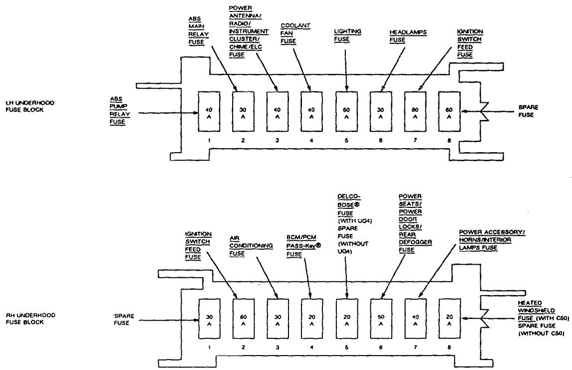
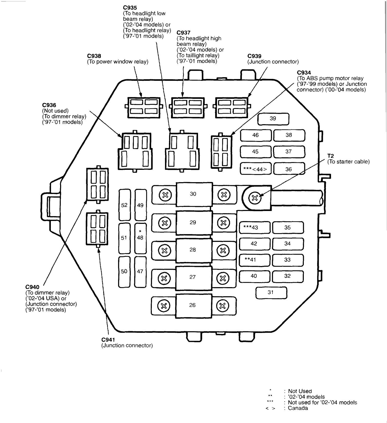
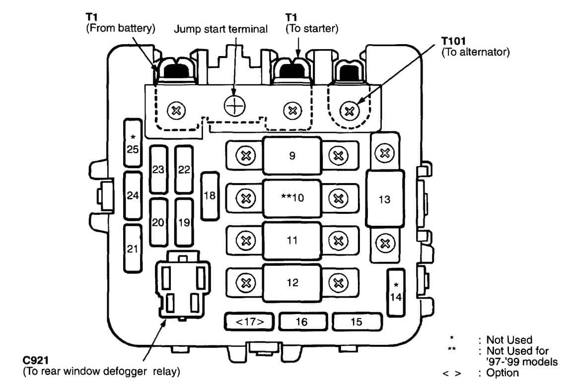
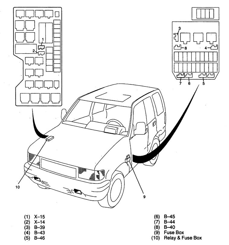
Underhood (U/H) electrical center
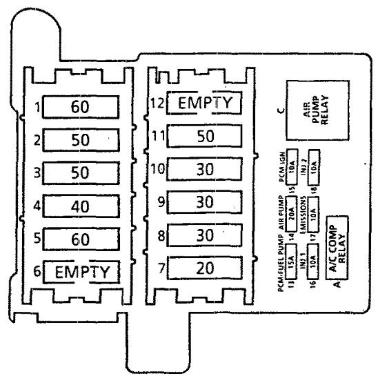
Cadillac Commercial Chassis – fuse box diagram – engine compartment
| Maxi Fuse | Name | Description |
| 1 | BODY 1 | 60 amp power to PWR ST Circuit Breaker, #3 30 amp. RR DEFG Circuit Breaker, #4 30 amp. I/P Fuse Block, #36 TRK PDWN 15 amp. #31 HAZARD LTS 20 amp, #39 PWR LUMB 20 amp, #40-HTD SEAT 20 amp #44 STOP LTS 20 amp, #45 PWR LK 20 amp |
| 2 | BODY 2 | 50 amp power to I/P Fuse Block #21 RAP BAT 25 amp. #22 HVAC MDL 25 amp, #26 ELC SENS 20 amp. #27 D/INT LTS 15 amp. #28 F’RT CIG 10 amp, #29 RRCIG 20 amp. #30 EBTCM 25 amp. #33-HVAC BAT 10 amp, #34-CCM BAT 10 amp. #35 PWR MIR 10 amp, #2 Circuit Breaker RAP RLY 30 amp. |
| 3 | IGN 1 | 60 amp power to I/P Concealed Fuse 5 amp, I/P Fuse Block, #6 T/SIG 15 amp, #7 EBTCM/TPS 10 amp, #8 RAP WPR 25 amp, #9 RADIO 10 amp, #10 WIPER 25 amp, #11 I/P INDC 10 amp, #12 ELC IGN 1 10 amp, #13 CHIME 10 amp, #14 CCMIGNI 10 amp, #15 AIR BAG 15 amp, #24 STARTER 10 AMP, U/H Electrical Cente, #15 PCM/IGN 10 amp, #16 I 10 amp, #17 EMissions 10 AMP, #18 INJ 2 10 AMP |
| 4 | — | — |
| 5** | ABS/TCS | 40 amp power to ABS/TC Brake Pressure Modulator Valve (BPMV) |
| 6** | ABS/TCS | 20 amp power to ABS/TC Brake Pressure Modulator Valve (BPMV) |
| 7 | SCNDRY CLG FAN | 40 amp power to Secondary Engine Cooling Fan Relay |
| 8 | PRIMARY CLG FAN | 40 amp power to Primary Engine Cooling Fan Relay |
| 9 | LEVEL CONTROL | 30 amp power to Automatic Level Control (ALC) Air Compressor |
| 10 | ENGINE | 30 amp power to U/H Electrical Center, #13 PCM/FUEL PUMP 15 amp #14 AIR PUMP 20 amp |
| 11 | HEADLIGHTS/HORNS | 50 amp power to I/P Flue Block Circuit Breaker, #5 HDLT’S 20 amp, Fuse #31 PARK LTS 20 amp, #32 HORN 25 amp |
| 12 | — | — |
| Mini Fuse | Name | Description |
| 13 | PCM/FUEL PUMP | 15 amp power to Fuel Pump Relay, Fuel Pump/Engine Oil Pressure Indicator Switch, Powertrain Control Module (PCM) |
| 14 | AIR PUMP | 20 amp power to Secondary Air Injection (AIR) Pump Relay |
| 15 | PCM/IGN | 10 amp power to Powertrain Control Module (PCM), Electronic Transmission Ignition Coil, Electronic Brake Control Module |
| 16 | INJ 1 | 10 amp power to fuel Injectors Cylinders 1-4, 6-7 |
| 17 | EMISSIONS | 15 amp power to Exhaust Gas Recirculation (EGA), Vacuum Control Signal Solenoid Valve, Secondary Air Injection (AIR) Pump Relay (coil), Mass Air Flow (MAF) sensor, Bank 1 (left) Heated Oxygen Sensor (H02S), Bank 2 (right) Heated Oxygen Sensor (H02S), Evaporative Emission (EVAP) Canister Purge Solenoid Valve |
| 18 | INJ 2 | 10 amp power to fuel Injectors Cylinders 2-3, 5-8 |
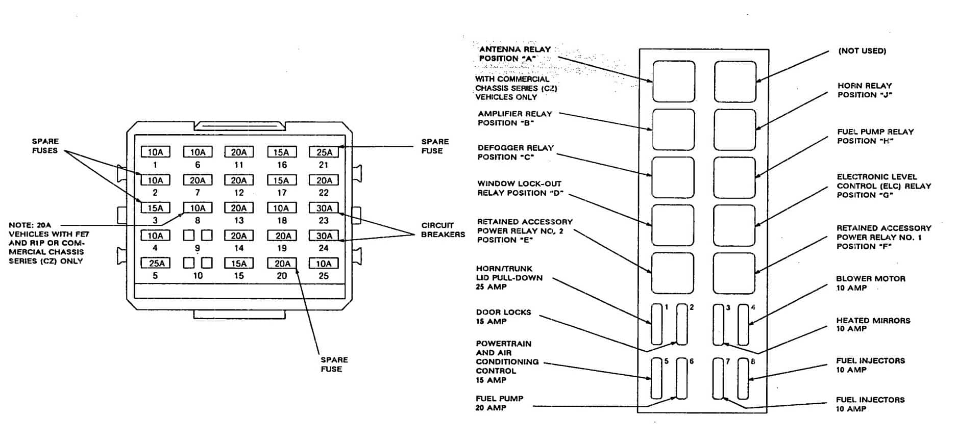
| Relay | Name | Description |
| A | A/C COMP RELAY | A/C Compressor Relay |
| B | AIR PUMP RELAY | Secondary Air lnjection (AIR) Pump Relay |
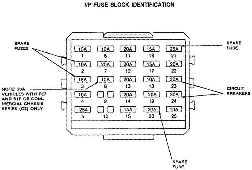
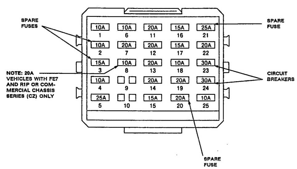
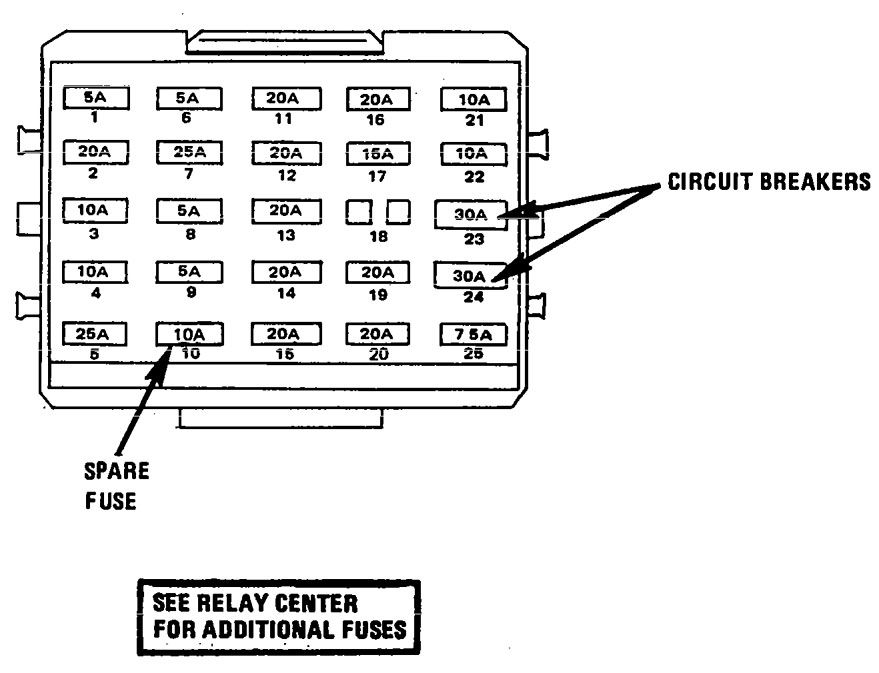
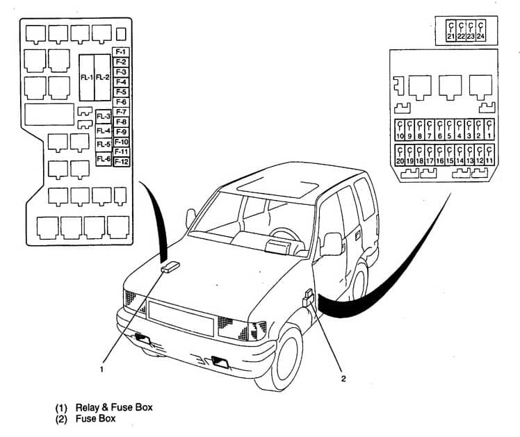
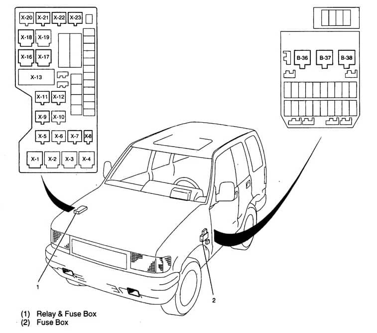
Instrument panel
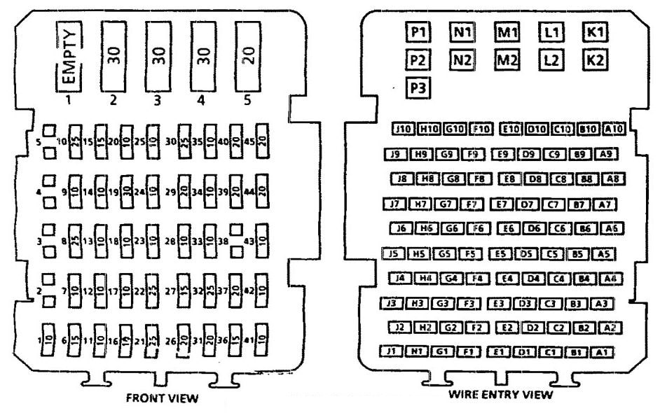
Cadillac Commercial Chassis – fuse box diagram – instrument panel
| Fuse | Name | Description |
| 1 | — | — |
| 2 | — | — |
| 3 | — | — |
| 4 | — | — |
| 5 | — | — |
| 6 | — | — |
| 7 | — | — |
| 8 | RAP WPR | Component Center (RAP Wiper) Relay |
| 9 | RADIO | Radio Receiver |
| 10 | WIPER | Windshield Wiper/Washer Switch |
| 11 | LP/NDC | Inflatable Restraint Diagnostic Energy reserve (with sensor) Module, Instrument Panel Cluster |
| 12 | T/SIG | Park/Neutral Positive and Backup Lamp Switch, Turn Signal Lamp |
| 13 | CHIME | Warning Alarm, Cruise Control Release Switch, Inside Rearview Mirror (DDB), Rear Window Defogger Relay, Catalytic Converter Temperature Alarm Module (UD6, Japan only), Park/Neutral Position and Backup Lamp Switch, Autmatic Level Control Sensor |
| 14 | CCM IGN 1 | Central Control Module (CCM) |
| 15 | AIR BAG | Inflatable Restraint Diagnostic Energy Reserve (with sensor) Module (SDM) |
| 16 | GEN | Generator, Secondary Electrical Engine Cooling Fan Relay |
| 17 | MEM SEAT | Driver’s Seat Adjuster Memory Module, Heated Driver Seat Control Module, Heated Passenger Seat Control Module |
| 18 | CCM IGN 3 | Central Control Module (CCM), Remote Control Door Lock Receiver and Theft Deterrent Module, Cruise Control Module Cruise Control Switch |
| 19 | RAP PWR | Accessory Time Delay Cut-off (RAP Power) Relay |
| 20 | A/C COMP | A/C Compressor Relay, Primary Engine Cooling Fan Relay |
| 21 | RAP BATT | Component Center (RAP Wiper) Relay |
| 22 | HVAC MDL | Blower Motor Control Module |
| 23 | TRK REL | Rear Compartment Lid Release Switch |
| 24 | STARTER | Theft Deterrent Relay, Inflatable Restraint Diagnostic Energy Reserve (with sensor) Module (SDM) |
| 25 | HVAC IGN | Instrument Cluster Heater-A/C Control, Vacuum/Electric Solenoid, Electric Actuator |
| 26 | ELC SENS | Automatic level Control Sensor, Rear Compartment Courtesy Lamp |
| 27 | D/INT LTS | Component Center (DIL) Relay |
| 28 | FRT CIG | Front Cigar Lighter |
| 29 | RR CIG | Rear Cigar Lighters |
| 30 | EBTCM | Electronic Brake and Traction Control Module (EBTCM) |
| 31 | PARK LTS | Park Lamp Relay |
| 32 | HORN | Horn Relay |
| 33 | HVAC BAT | Warning Alarm, Heater A/C Control, Headlamp Switch, Radio Receiver |
| 34 | CCM BAT | Central Control Module (CCM) |
| 35 | PWR MIR | Door Lock Switch, Outside Rearview Mirrors, Ignition Key Disable Relay Assembly |
| 36 | TRK PDWN | Rear Compartment Lidl Pull-Down Actuator |
| 37 | HAZARD LTS | Hazard Lamp Flasher |
| 38 | STOP LTS | Stoplamp Switch |
| 39 | PWR LUMB | Door Lock Relay |
| 40 | HTD SEAT | Heated Driver’s Seat Control Module, Heated Passenger Seat Control Module |
| 41 | CORNR LTS | Instrument Cluster, Radio Control, Cornering Lamps, Turn Signal Switch, Front Park Lamps |
| 42 | I/P DIM LTS | Headlamp Switch, Interior Lamps, Dimming |
| 43 | TAIL LTS | Rear Taillamps, Rear Side Marker Lamps, License lamp |
| 44 | MIR DEFG | Outside Rearview Mirror Defogger |
| 45 | — | — |
| Circuit Breaker | Name | Description |
| 1 | PWR RECL | Lumbar, Power Antenna |
| 2 | RAP RLY | Accessory Time Delay Cut-off (RAP Power) Relay |
| 3 | PWR SEAT | Driver’s Power Seat Switch, Passenger Power Seat Adjuster Switch, Driver’s Seat Adjuster Memory Module, Driver’s Seat Recline Switch, Passenger Seat Recline Switch |
| 4 | RR DEFG | Rear Defogger Relay |
| 5 | HDLTS | Headlamp Relay, Daytime Running Lamps (DRL) Module |
WARNING: Terminal and harness assignments for individual connectors will vary depending on vehicle equipment level, model, and market.