Back-up light, combination meter <non-turbo>, EATX-ECM <non-turbo (A/T) and SRS-ECU
4
10
Turn signal and hazard flasher unit
Battery
5
10
Theft-alarm horn and theft-alarm horn relay
6
30
Defogger and defogger switch
Ignition switch
IG2
7
—
—
IG1
8
10
Auto-cruise main switch, auto-cruise control vacuum pump <turbo>, auto-cruise-ECU, auto-cruise speed control assembly <non-turbo>, combination meter, ETACS-ECU, powertrain control module <non-turbo>, SRS-ECU and sunroof-ECU
ACC
9
20
ETACS-ECU, intermittent wiper relay, wiper and washer motor
Battery
10
10
Door lock actuator and door lock power relay
11
30
Blower motor
Ignition switch
ACC
12
—
—
IG2
13
10
ABS-ECU <FWD>, ABS power relay <AWD>, A/C switch, automatic compressor-ECM, blower motor relay, defogger relay and DRL-ECU <CANADA>
ACC
14
15
Cigarette lighter
IG2
15
10
Auto-cruse-ECU <turbo>, combination meter <turbo> and ELC 4-speed automatic transaxle control module <turbo>
Battery
16
—
—
17
20
Sunroof-ECU
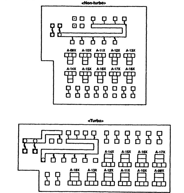
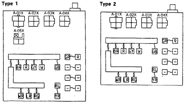
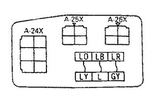
WARNING: Terminal and harness assignments for individual connectors will vary depending on vehicle equipment level, model, and market.
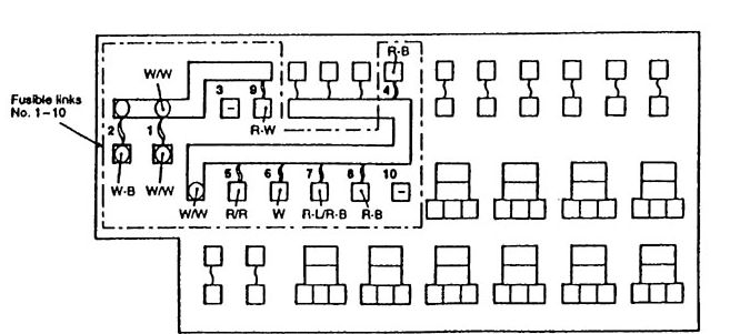
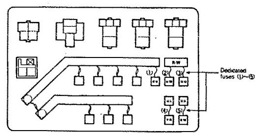
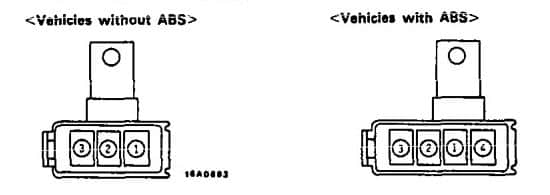
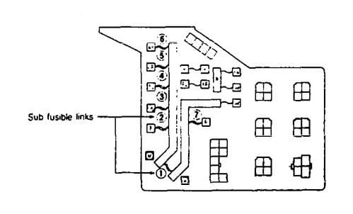
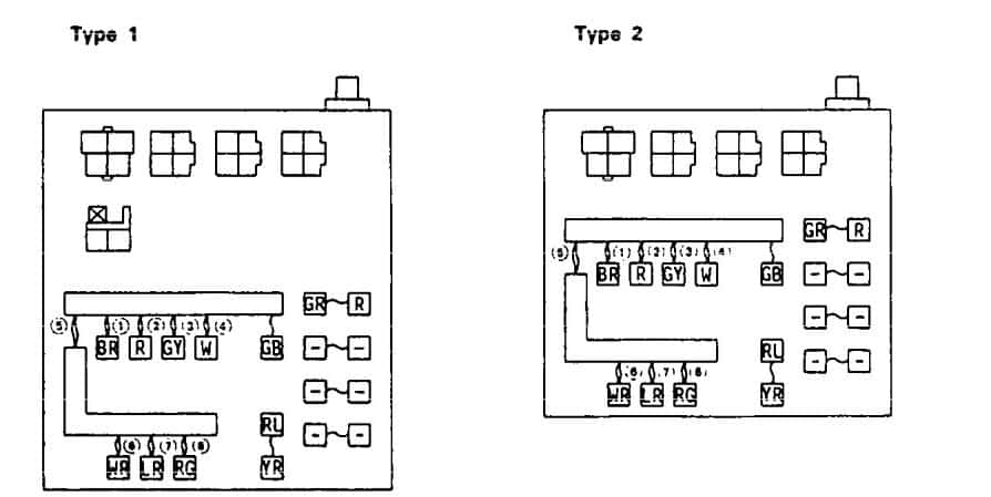
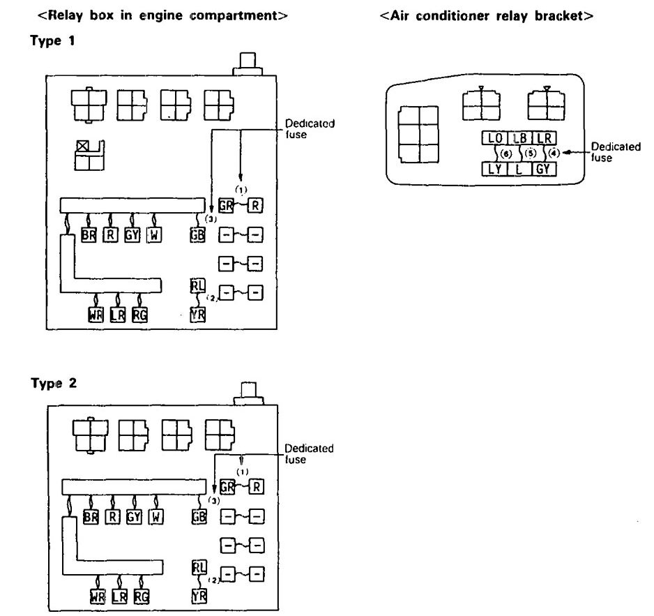
Fusible link No. (6), (7), (8) <when the engine is stopped> and Fusible link No, (2), (3), (4), (5), (9) dedicated fuse No. (1) <after start of the engine> circuit
Black
80
2
MFI circuit
Blue
20
3
Headlight, taillight and generator circuit
Pink
30
4
Radiator fan motor, condenser fan motor and A/C compressor circuit
Pink
30
5
Ignition switch circuit
Green
40
6
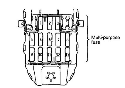
Multi-purpose fuse (in the junction block) No. (1), (6), (8), (13), (14)
Back-up light, buzzer assembly and combination meter <3A/T>, SRS diagnosis unit
3
10
Red
Combination meter, buzzer assembly and auto-cruise control main switch
ACC
4
15
Blue
Cigarette lighter and remote controlled mirror
5
10
Red
Clock, radio and tape player and auto-cruise control unit
Battery
6
15
Blue
Stop light
Ignition switch
IG1
7
10
Red
Turn signal and hazard flasher unit, SRS diagnosis unit
Battery
8
15
Blue
Door lock control relay
Ignition switch
ACC
9
10
Red
Horn
10
15
Blue
Wiper and washer motor
—
11
—
—
—
Battery
12
—
—
—
13
—
—
—
14
10
Red
Dome light, luggage compartment light, clock, radio and tape player, combination meter, door lock control relay, engine control module, transaxle control module
Ignition switch
IG2
15
10
Red
Blower motor relay, defogger relay, power window relay, automatic compressor control unit, ABS power relay, ABS valve relay and DRL control unit, buzzer assembly, auto-cruise control unit and automatic seat belt control unit
16
—
—
—
17
10
Red
Cobination meter (4A/T> and transaxle control module
Automatic seat belt control unit,buzzer assembly, fog light relay, key reminder switch *2
Ignition switch
IG2
2
—
—
3
10
Air conditioner contlol unit, air conditioner switch blower, defogger timer, heater relay, power window relay, transistor relay*1, daytime running light relay 2*1, ABS relay
ACC
4
10
Radio
5
15
Cigarette lighter, remote controlled mirror
Battery
6
15
Door lock relay, door lock control unit
Ignition switch
IG2
7
10
A/T fluid temperature warning light, 4-speed automatic transaxle control unit, auto-cruise control unit <A/T>
8
—
—
ACC
9
15
Intermittent wiper relay, wiper motor, washer motor
10
10
Headlight relay, horn, daytime running high relay 1*1
IG1
11
10
Auto-cruise control unit, auto-cruise control actuator, automatic seat belt control unit, buzzer assembly, combination meter, seat belt warning light*
12
10
Tum-signal and hazard flasher unit
Battery
13
—
—
14
—
—
15
—
—
16
30
Blower motor
17
15
Stop light
Ignition switch
IG1
18
10
Back-UP light, dome light relay
Battery
19
10
4-speed automatic transaxle control unit, dome light, door-ajar warning light, foot light, ignition key illumination light, luggage compartment light, MPI control unit, radio, ABS relay, automatic seat belt control unit, ABS control unit door lock control unit
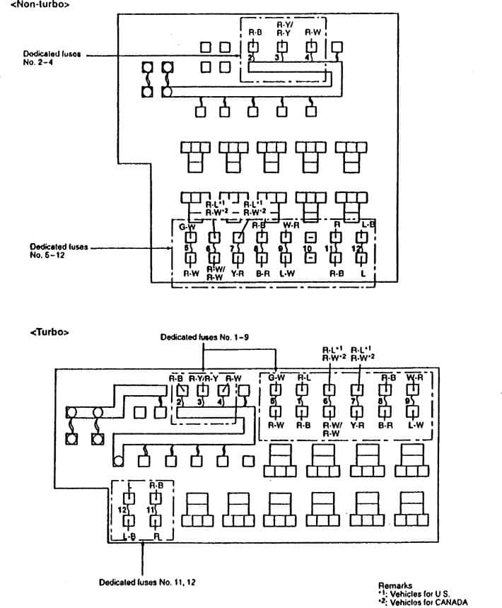
(1) *1: vehicle for Canada
(2) *2: vehicle for USA
WARNING: Terminal and harness assignments for individual connectors will vary depending on vehicle equipment level, model, and market.
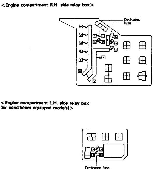
Fusible link No. (6), (7), (8) <when the engine is stopped> and Fusible link No, (2), (3), (4), (5), (6) dedicated fuse No. (2) <after start of the engine> circuit
Black
80
2
MFI circuit
Blue
20
3
Headlight, taillight and generator circuit
Pink
30
4
Radiator fan motor, condenser fan motor and A/C compressor circuit
Pink
30
5
Ignition switch circuit
Green
40
6
Multi-purpose fuse (in the junction block) No. (1), (6), (8), (12), (14)
Green
40
7
Power window circuit
Pink
30
8
Defogger circuit
Blue
20
9
ABS circuit
Yellow
60
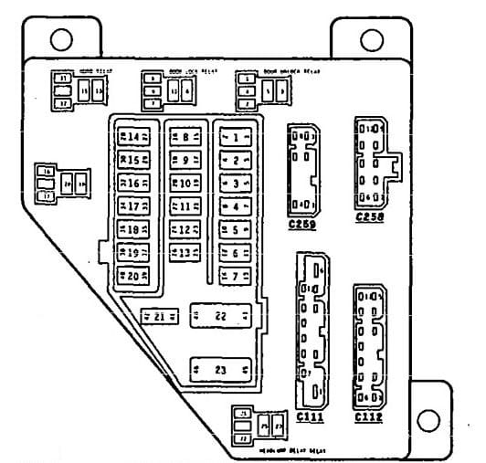
Eagle Summit – fuse box diagram
Power supply circuit
No
A
Housing color
Circuit
Battery
1
10
Red
Hazard light circuit
Tailight relay (Battery)
2
10
Red
Tailight and illumination circuit
3
—
—
—
Headlight relay (Battery)
4
10
Red
Upper beam indicator circuit
Battery
5
10
Red
ABS circuit
Eagle Summit – fuse box diagram
Power supply circuit
No.
A
Housing color
Load circuit
Battery
1
20
Yellow
Blower motor
Ignition switch
IG1
2
10
Red
Back-up light, buzzer assembly and combination meter <3A/T>
3
10
Red
Combination meter, buzzer assembly and auto-cruise control main switch
ACC
4
15
Blue
Cigarette lighter and remote controlled mirror
5
10
Red
Clock, radio and tape player and auto-cruise control unit
Battery
6
15
Blue
Stop light
Ignition switch
IG1
7
10
Red
Turn signal and hazard flasher unit
Battery
8
15
Blue
Door lock control relay
Ignition switch
ACC
9
10
Red
Horn
10
15
Blue
Wiper and washer motor
—
11
—
—
—
Battery
12
—
—
—
13
—
—
—
14
10
Red
Dome light, luggage compartment light, clock, radio and tape player, combination meter, door lock control relay, engine control module, transaxle control module
Ignition switch
IG2
15
10
Red
Blower motor relay, defogger relay, power window relay, automatic compressor control unit, ABS power relay, ABS valve relay and DRL control unit, buzzer assembly, auto-cruise control unit and automatic seat belt control unit
16
—
—
—
17
10
Red
Cobination meter (4A/T> and transaxle control module
WARNING: Terminal and harness assignments for individual connectors will vary depending on vehicle equipment level, model, and market.
Automatic seat belt control unit,buzzer assembly, fog light relay, key reminder switch *2
Ignition switch
IG2
2
—
—
3
10
Air conditioner contlol unit, air conditioner switch blower, defogger timer, heater relay, power window relay, transistor relay*1, daytime running light relay 2*1, ABS relay
ACC
4
10
Radio
5
15
Cigarette lighter, remote controlled mirror
Battery
6
15
Door lock relay, door lock control unit
Ignition switch
IG2
7
10
A/T fluid temperature warning light, 4-speed automatic transaxle control unit, auto-cruise control unit <A/T>
8
—
—
ACC
9
15
Intermittent wiper relay, wiper motor, washer motor
10
10
Headlight relay, horn, daytime running high relay 1*1
IG1
11
10
Auto-cruise control unit, auto-cruise control actuator, automatic seat belt control unit, buzzer assembly, combination meter, seat belt warning light*
12
10
Tum-signal and hazard flasher unit
Battery
13
—
—
14
—
—
15
—
—
16
30
Blower motor
17
15
Stop light
Ignition switch
IG1
18
10
Back-UP light, dome light relay
Battery
19
10
4-speed automatic transaxle control unit, dome light, door-ajar warning light, foot light, ignition key illumination light, luggage compartment light, MPI control unit, radio, ABS relay, automatic seat belt control unit, ABS control unit door lock control unit
(1) *1: vehicle for Canada
(2) *2: vehicle for USA
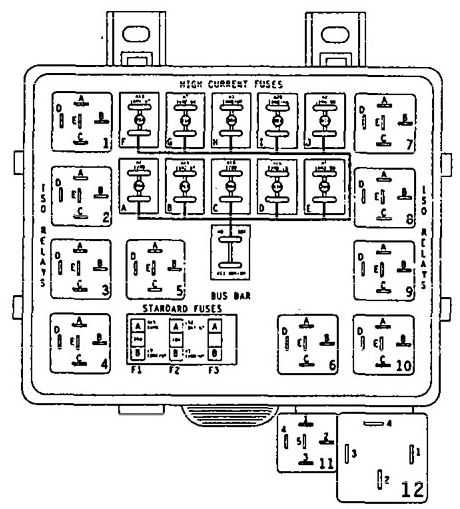
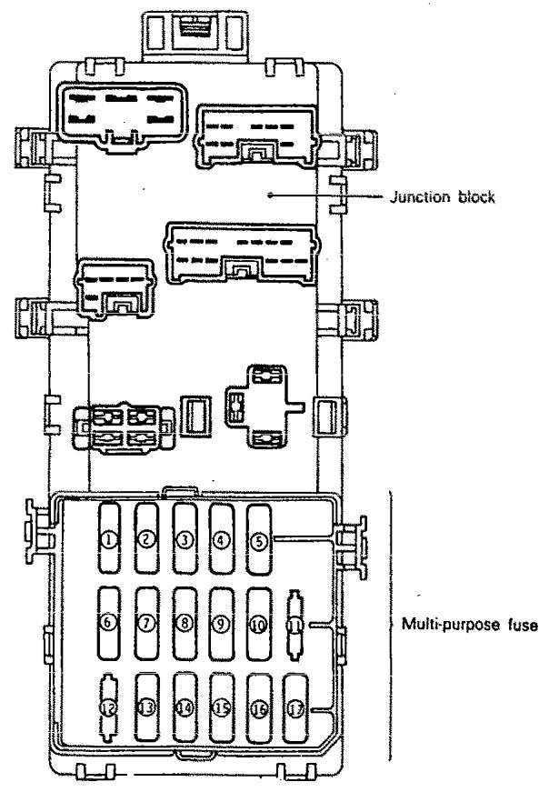
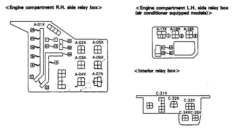
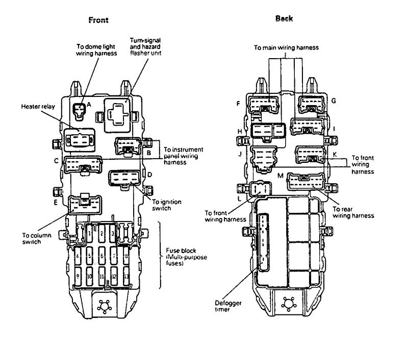
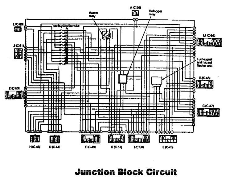
Centralized Junction Block
Eagle Talon – fuse box diagram – centralized junction block
No.
Circuit
Housing color
A
1
MPI circuit
Blue
20
2
Radiator fan motor circuit
Pink
30
3
Ignition fan motor circuit
Pink
30
4
ABS circuit
Yellow
60
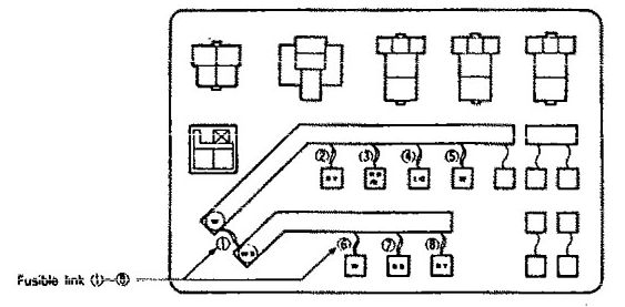
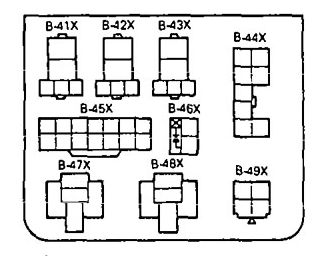
Sub Fusible link (relay box inside engine compartment)
Eagle Talon – fuse box diagram – centralized junction block – sub fusible link
No.
Circuit
Housing color
A
1
Alternator circuit, sub fusible link (2), (3), (4), (6), (8)
Windshield wiper and washer. Rear wiper and washer
IG1
2
10
Meter and gauges. indicator lights. warning lights, clutch switch <M/T>, seat belt warning timer
ACC
3
10
Radio, clock
IG2
4
10
4 A/T control unit. overdrive switch <4 A/T>, inhibitor switch <4 A/T>, auto-cruise control unit <4 A/T>
IG1
5
10
Back-up light. inhibitor switch <3 A/T, 4 A/T>, hazard warning light, 3 A/T control unit
ACC
6
10
Horn. headlight relay, upper beam relay
7
15
Cigarette lighter, remote-controlled mirror
Battery
8
10
Dome light, luggage compartment light, clock, radio, MPI control unit, 4 A/T control unit, door-ajar warning light, automatic seat belt control unit, seat belt warning buzzer, key reminder switch
Ignition switch IG2
9
10
Power window relay, defogger relay, deffoger timer, defogger switch, heater relay, blower switch, auto compressor control unit, DRL control relay, DRL control unit