Isuzu i-280 (2006) – fuse box diagram
Year of production: 2006
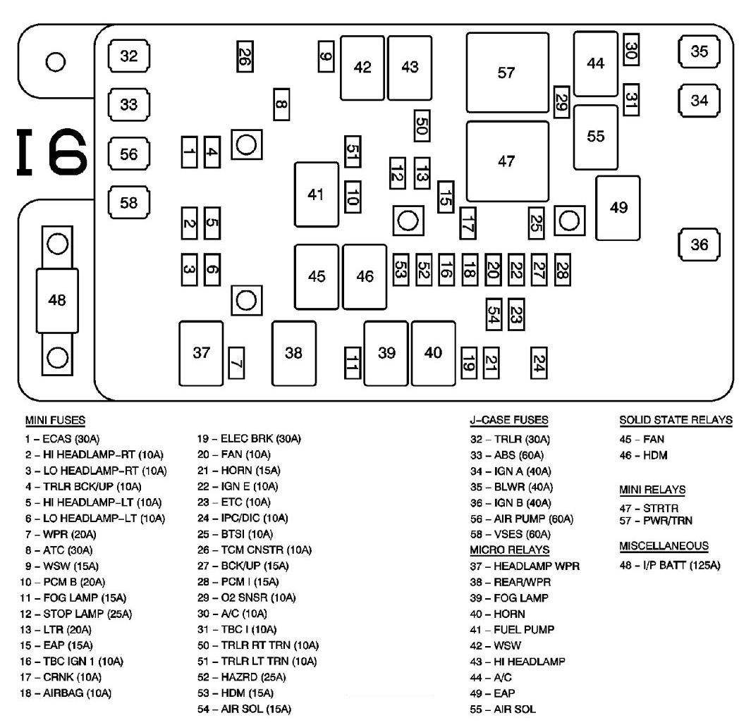
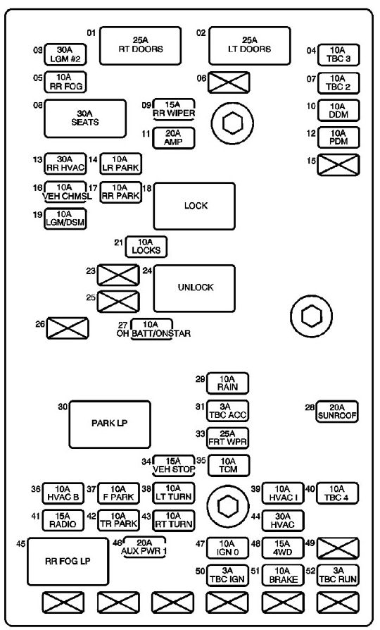
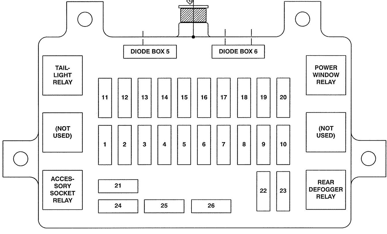
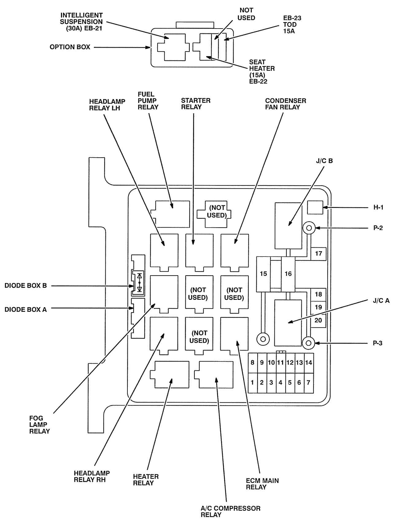
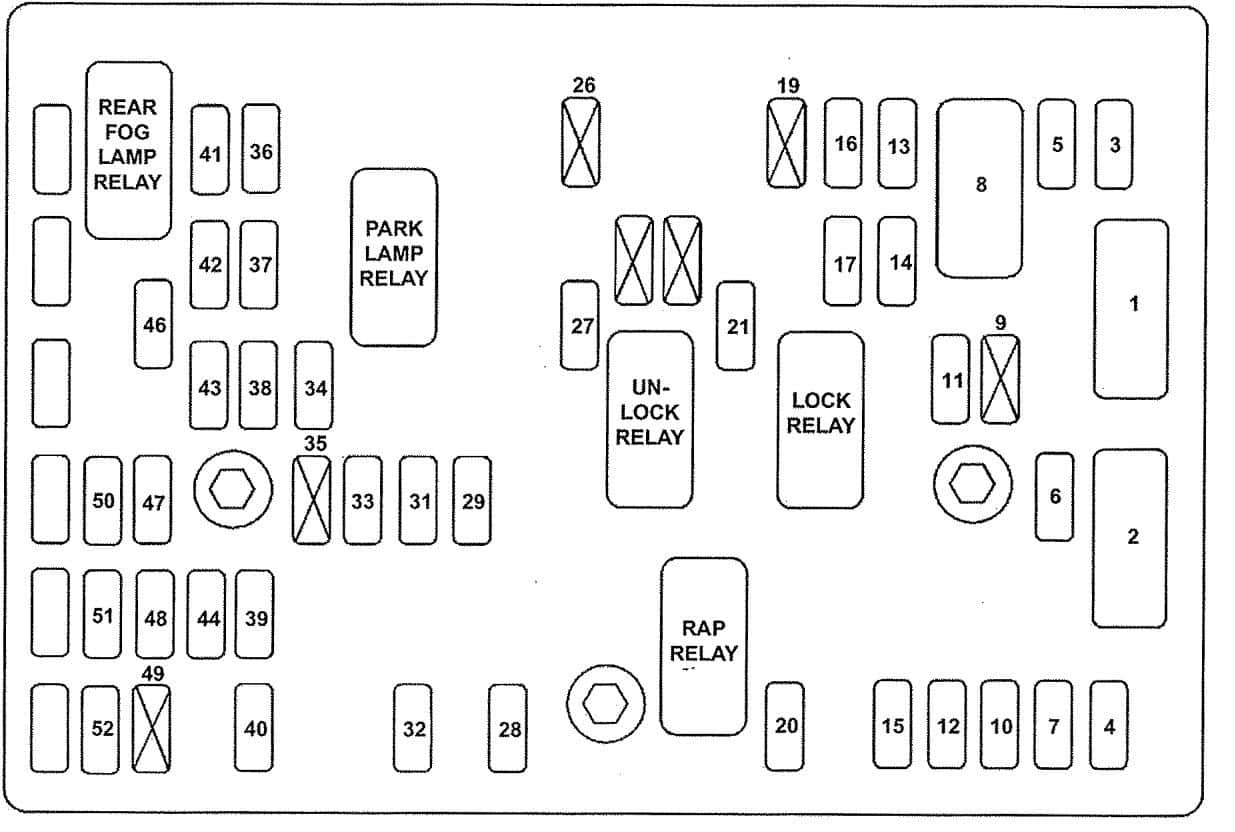
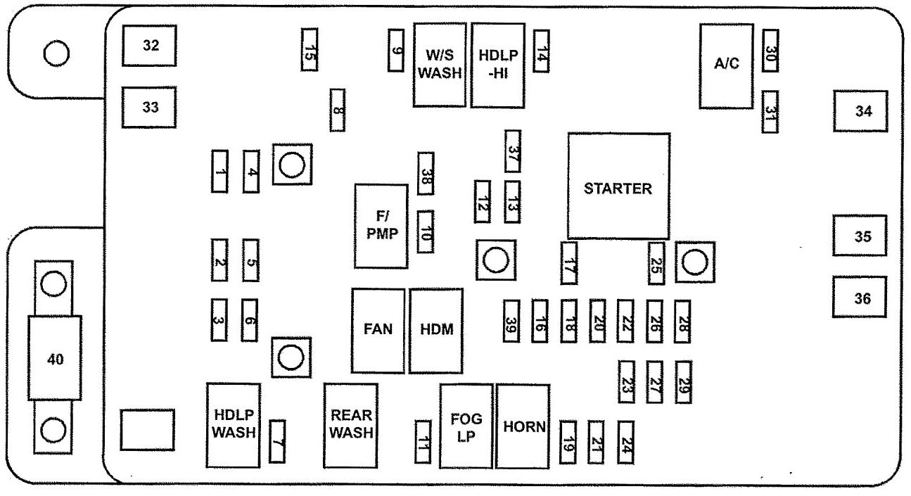
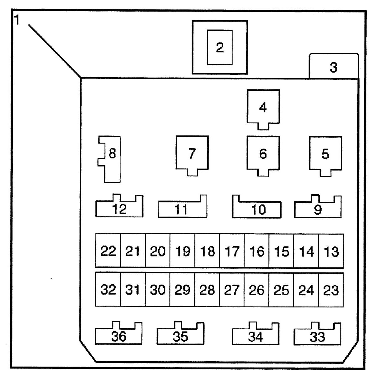
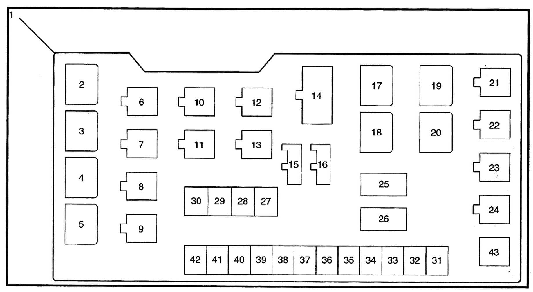
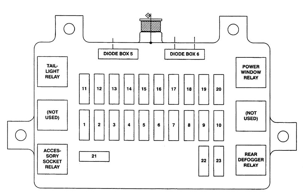
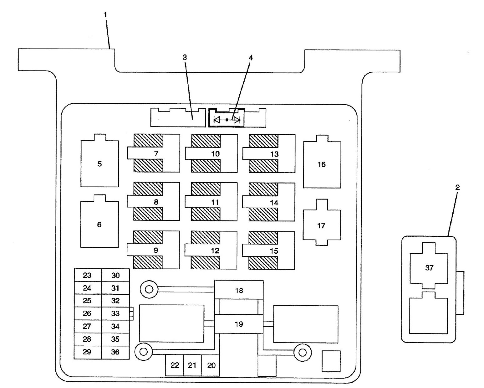
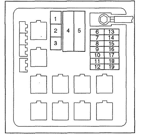
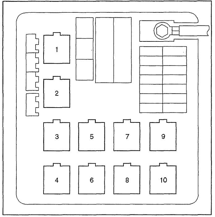
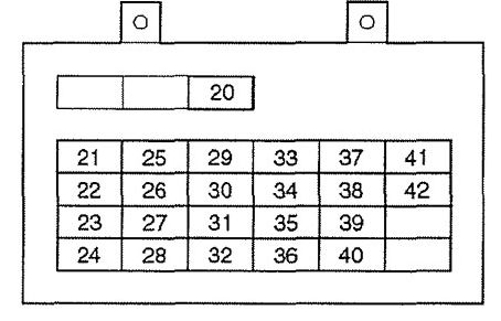
Fuse box diagram
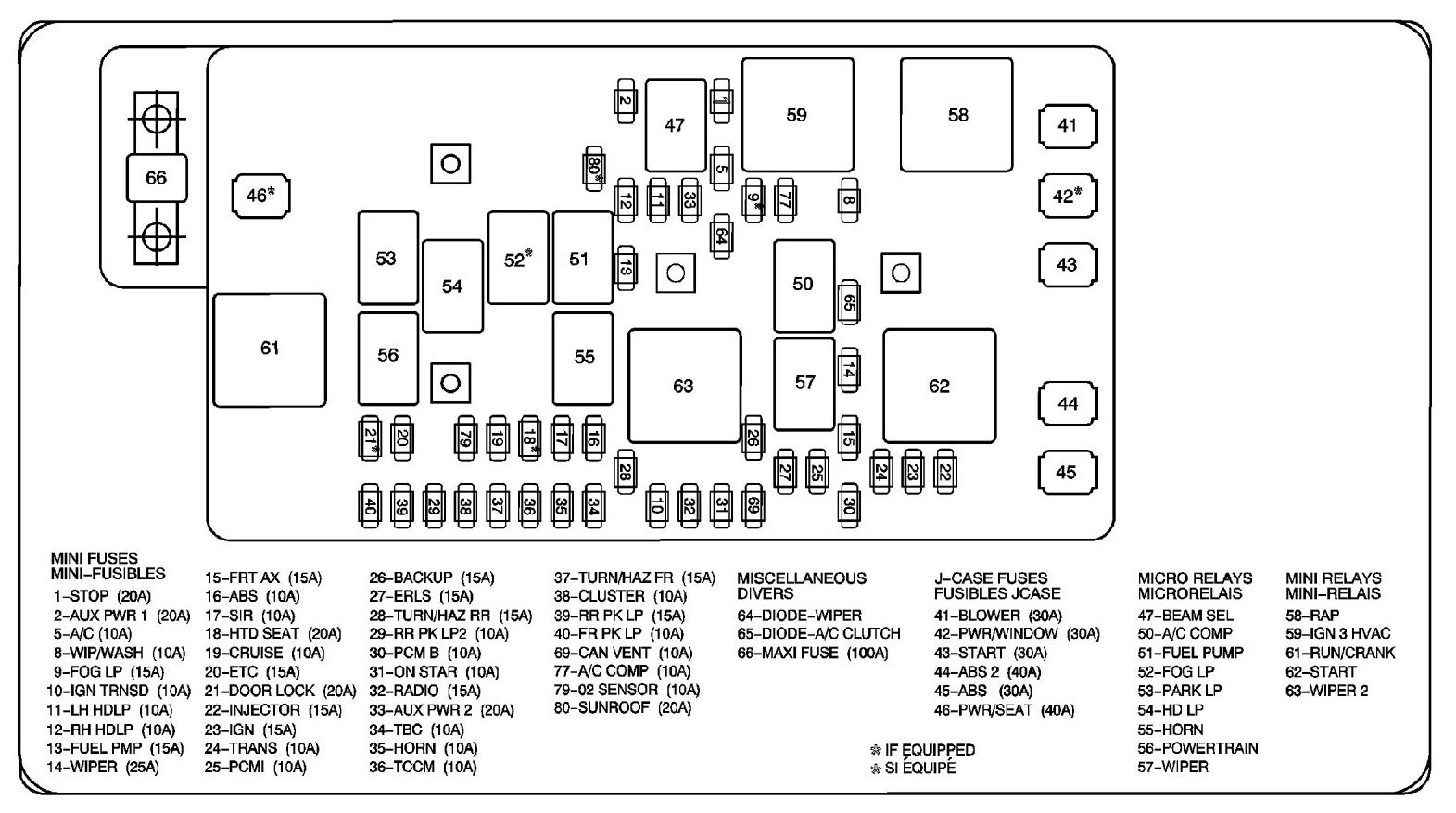
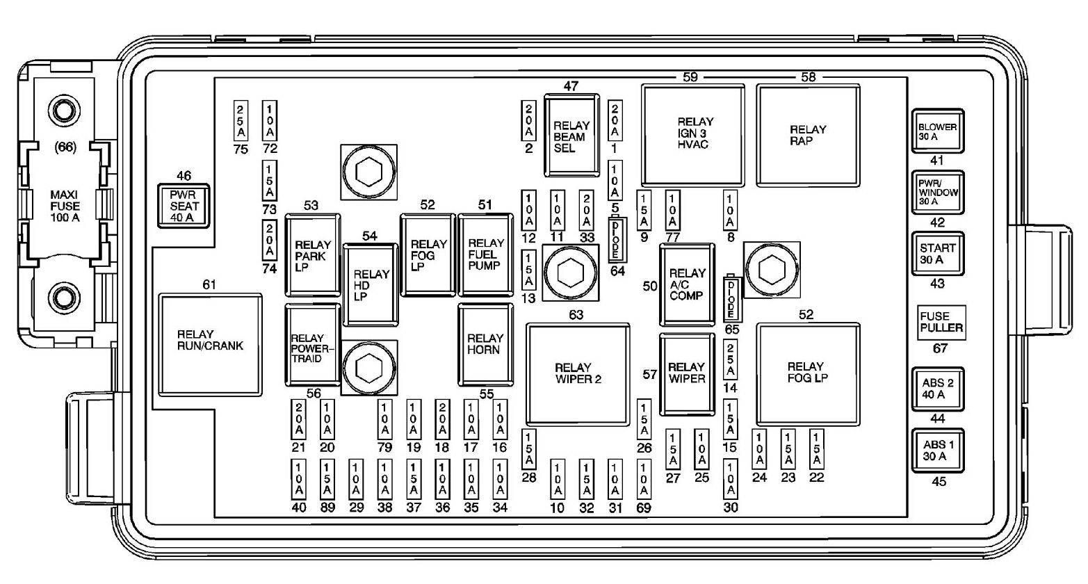
| No | Fuse name | A | Description |
| 1 | STOP | 20 | Stop Lamp Switch |
| 2 | AUX | 20 | Auxiliary Power Outlets, Data Link Connector (DLC) |
| 5 | A/C | 10 | HVAC Control Module, Driver Seat Module (Heated Seat Switch), Passenger Seat Module (Heated Seat Switch) |
| 8 | WIP/WASH | 10 | Windshield Wiper/Washer Switch |
| 9 | FOG LP (T96) | 15 | Fog Lamp Relay |
| 10 | IGN TRNSD | 10 | Ignition Switch (Transducer) |
| 11 | LH HDLP | 10 | Headlamp Assembly – Left |
| 12 | RH HDLP | 10 | Headlamp Assembily – Right |
| 13 | FUEL PMP | 15 | Fuel Pump |
| 14 | WIPER | 25 | Windshield Wiper Relay |
| 15 | FRT AX | 15 | Front Axle Actuator (4WD) |
| 16 | ABS | 10 | Electronic Brake Control Module (EBCM), Yaw Rate Sensor (4WD) |
| 17 | SIR | 10 | Inflatable Restraint Sensing and Diagnostic Module (SDM), Inflatable Restraint 1/P Module Disable Switch (C99) |
| 18 | HTD SEAT | 20 | Heated Seat Assembly – Driver, Heated Seat Assembly – Passenger |
| 19 | CRUISE | 10 | Inside Rearview Mirror w/Reading Lamps (DC4 w/UE1 or DF8), Cruise Control Switch (K34), Transfer Case Control Module (NP1) |
| 20 | ETC | 15 | Powertrain Control Module (PCM) |
| 21 | DOOR LOCK | 20 | Door Lock Switch – Driver (AU3) |
| 22 | INJECTOR | 15 | Fuel Injectors |
| 23 | IGN | 15 | Clutch Start Switch (MAS), Ignition Coil 1 Module, Ignition Coil2 Module, Ignition Coil 3 Module, Ignition Coil 4 Module, Ignition Coil 5 Module (3.5L), Park/Neutral Position (PNP) Switch (M30), A/C Compressor Clutch Relay |
| 24 | TRANS | 10 | Transmission Solenoids |
| 25 | PCM | 10 | Powertrain Control Module (PCM)- C1 |
| 26 | BACKUP | 15 | Park/Neutral Position (PNP) Switch |
| 27 | ERLS | 15 | Evaporative Emission (EVAP) Canister Purge Solenoid Valve, MAF!IAT Sensor |
| 28 | TURN/HAZ RR | 15 | Body Control Module (SCM) (Bulb Out- LR, RR Turn Signal) |
| 29 | RR PK LP2 | 10 | Left Tail Lamp Assembly, Body Control Module (BCM)- Dimmed Lights, Passenger Airbag Indicator |
| 30 | PCM B | 10 | Powertrain Control Module (PCM)- C1 (Battery) |
| 31 | ON STAR | 10 | Vehicle Communication Interface Module (VCIM) |
| 32 | RADIO | 15 | Radio |
| 33 | CIGAR | 20 | Cigar Lighter |
| 34 | TBC | 10 | Body Control Module (BCM)- C1 |
| 35 | HORN | 10 | Horn Relay |
| 36 | TCCM | 10 | Transfer Case Shift Control Module ( 4WD) |
| 37 | TURN/HAZ FR | 15 | Body Control Module (BCM) (Bulb Out- LF, RF Turn Signal) |
| 38 | CLUSTER | 10 | Instrument Panel Cluster (IPC) |
| 39 | RR PK LP | 15 | Right Tail Lamp Assembly, License Lamps |
| 40 | FR PK LP | 10 | Park Lamp- LF, Park Lamp- RF, Window Switch- Driver, Window Switch- Passenger, Window Switch – LR (Crew Cab), Window Switch-RR (Crew Cab) |
| 41 | BLOWER | 30 | HVAC Blower Motor |
| 42 | PWR/WINDOW | 30 | Power Window- Driver, Power Window- Passenger, Power Window-RR (Crew Cab), Power Window-LR (Crew Cab) |
| 43 | START | 30 | START Relay |
| 44 | ABS 2 | 40 | Electronic Brake Control Module (EBCM) (Relay) |
| 45 | ABS 1 | 30 | Electronic Brake Control Module (EBCM) |
| 46 | PWR/SEAT | 40 | Seat- Driver (Circuit Breaker} |
| 47 | BEAM SEL Relay | — | Headlamp- LH (w/o TT5), Headlamp- RH (w/o TIS), Headlamp- Low Beam – Right/Left (TT5), Headlamp – High Beam- Right/Left (TT5) |
| 50 | A/C COMP Relay | — | AIC Compressor Clutch Relay |
| 51 | FUEL PUMP Relay | — | Fuel Tank Pressure (FTP) Sensor, Fuel Pump and Sender Assembly |
| 52 | FOG LP Relay (T96) | — | Fog Lamp- LF, Fog Lamp- RF |
| 53 | PARK LP Relay | — | FR PK LP Fuse, RR PK LP Fuse, RR PK LP2 Fuse` |
| 54 | HD LP Relay | — | RH HDLP Fuse, LH HDLP Fuse |
| 55 | HORN Relay | — | Horn Assembly |
| 56 | POWERTRAIN Relay | — | ETC Fuse, 02 Sensor Fuse |
| 57 | WIPER Relay | — | WIPER 2 Relay |
| 58 | RAP Relay | — | WIPER SW Fuse, PWR WOO Fuse |
| 59 | IGN 3 HVAC Relay | — | BLOWER Fuse. CNTRL HD Fuse |
| 61 | RUN/CRANK Relay | — | SIR Fuse, CRUISE Fuse, IGN Fuse, TRANS Fuse, BACK UP Fuse, ABS Fuse, ERLS Fuse, FRT AXLE CNTRL Fuse, PCM 1 Fuse and INJECTORS Fuse |
| 62 | START Relay | — | Starter Solenoid |
| 63 | WIPER 2 Relay | — | Windshield Wiper Motor |
| 64 | Diode | — | Wiper Relays (Between) |
| 65 | Diode | — | AIC Clutch |
| 66 | Maxi Fuse | 100 | Generator |
| 67 | Fuse Puller (If Equipped) | — | — |
| 69 | CAN VENT | 10 | Evaporative Emission (EVAP) Canister Vent Solenoid Valve |
| 72 | SPARE | 10 | Spare Fuse, If Equipped |
| 73 | SPARE | 15 | Spare Fuse, If Equipped |
| 74 | SPARE | 20 | Spare Fuse, If Equipped |
| 75 | SPARE | 25 | Spare Fuse, If Equipped |
| 77 | A/C COMP | 10 | A/C Compressor Clutch Relay |
| 79 | 02 SENSOR | 10 | Heated Oxygen Sensor (H02S) 1, Heated Oxygen Sensor (H02S) 2 |
WARNING: Terminal and harness assignments for individual connectors will vary depending on vehicle equipment level, model, and market.