Jeep Cherokee (1972 – 1983) – fuse box diagram

Jeep Cherokee (1972 – 1983) – fuse box diagram

Year of production: 1972, 1973, 1974, 1975, 1976, 1977, 1978, 1979, 1980, 1981, 1982, 1983

Fuse box

Jeep Cherokee – fuse box diagram

A
Protected Component
1 20 Windshield wipers
2 15 Turn signals
3 10 Accessories
4 3 Instrument and accessory lights
5 20 Interior lights
6 20 Brake, tail and parking lights
7 25 Air conditioner, heater and electric fan
8 3 Instruments
9 25 Seat belt warning and back-up lights
10 20 Hazard flasher, clock and stop lights
Relay
R1 Hazard flasher
R2 Turn signal
  • 24 amp. circuit breaker is located in the headlight switch to protect headlight circuit. All models have two 30 amp. circuit breakers located in the fuse block to protect the electric tailgate window. One circuit breaker protects the instrument panel switch and the other protects the tailgate switch.
  • The 6-cyl. models have a 4 amp. in-line fuse protecting the cruise control. The V8 models have a 1.5 amp. in-line fuse protecting the cruise control.
  • All Jeep models are equipped with fusible links, located in the engine compartment, which protect the circuits.


WARNING: Terminal and harness assignments for individual connectors will vary depending on vehicle equipment level, model, and market.

Jeep Wagoneer (1972 – 1983) – fuse box diagram

Jeep Wagoneer (1972 – 1983) – fuse box diagram

Year of production: 1972, 1973, 1974, 1975, 1976, 1977, 1978, 1979, 1980, 1981, 1982, 1983

Fuse box

Jeep Wagoneer - fuse box diagram
Jeep Wagoneer – fuse box diagram

A
Protected Component
1 20 Windshield wipers
2 15 Turn signals
3 10 Accessories
4 3 Instrument and accessory lights
5 20 Interior lights
6 20 Brake, tail and parking lights
7 25 Air conditioner, heater and electric fan
8 3 Instruments
9 25 Seat belt warning and back-up lights
10 20 Hazard flasher, clock and stop lights
Relay
R1 Hazard flasher
R2 Turn signal
  • 24 amp. circuit breaker is located in the headlight switch to protect headlight circuit. All models have two 30 amp. circuit breakers located in the fuse block to protect the electric tailgate window. One circuit breaker protects the instrument panel switch and the other protects the tailgate switch.
  • The 6-cyl. models have a 4 amp. in-line fuse protecting the cruise control. The V8 models have a 1.5 amp. in-line fuse protecting the cruise control.
  • All Jeep models are equipped with fusible links, located in the engine compartment, which protect the circuits.


WARNING: Terminal and harness assignments for individual connectors will vary depending on vehicle equipment level, model, and market.

Jeep Scrambler (1978 – 1986) – fuse box diagram

Jeep Scrambler (1978 – 1986) – fuse box diagram

Year of production: 1978, 1979, 1980, 1981, 1982, 1983, 1984, 1985, 1986

Fuse box

Jeep Scrambler - fuse box diagram
Jeep Scrambler – fuse box diagram

A
Protected Component
1 4.5 Windshield wipers
2 15 Turn signals
3 10 Accessories
4 3 Instrument and accessory lights
5 20 Interior lights
6 20 Brake, tail and parking lights
7 25 Air conditioner, heater and electric fan
8 3 Instruments
9 10 6-cyl.: Seat belt warning and back-up lights
20 4-cyl.: Seat belt warning and back-up lights
10 20 Hazard flasher, clock and stop lights
Relay
R1 Hazard flasher
R2 Turn signal
  • 24 amp. circuit breaker is located in the headlight switch to protect headlight circuit.
  • The 6-cyl. models have a 4 amp. in-line fuse protecting the cruise control. The V8 models have a 1.5 amp. in-line fuse protecting the cruise control.
  • All Jeep models are equipped with fusible links, located in the engine compartment, which protect the circuits.


WARNING: Terminal and harness assignments for individual connectors will vary depending on vehicle equipment level, model, and market.

Jeep CJ (1978 – 1986) – fuse box diagram

Jeep CJ (1978 – 1986) – fuse box diagram

Year of production: 1978, 1979, 1980, 1981, 1982, 1983, 1984, 1985, 1986

Fuse box

Jeep CJ - fuse box diagram
Jeep CJ – fuse box diagram

A
Protected Component
1 4.5 Windshield wipers
2 15 Turn signals
3 10 Accessories
4 3 Instrument and accessory lights
5 20 Interior lights
6 20 Brake, tail and parking lights
7 25 Air conditioner, heater and electric fan
8 3 Instruments
9 10 6-cyl.: Seat belt warning and back-up lights
20 4-cyl.: Seat belt warning and back-up lights
10 20 Hazard flasher, clock and stop lights
Relay
R1 Hazard flasher
R2 Turn signal
  • 24 amp. circuit breaker is located in the headlight switch to protect headlight circuit.
  • The 6-cyl. models have a 4 amp. in-line fuse protecting the cruise control. The V8 models have a 1.5 amp. in-line fuse protecting the cruise control.
  • All Jeep models are equipped with fusible links, located in the engine compartment, which protect the circuits.


WARNING: Terminal and harness assignments for individual connectors will vary depending on vehicle equipment level, model, and market.

Cadillac ESV (Second Generation; 2003 – 2004) – fuse box diagram

Cadillac ESV (Second Generation; 2003 – 2004) – fuse box diagram

Year of production: 2003, 2004

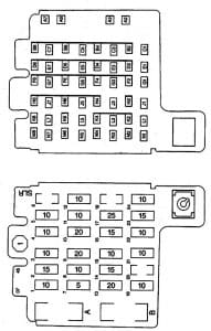
Instrument Panel Fuse Block

The fuse block access door is on the driver’s side edge of the instrument panel. Pull off the cover to access the fuse block.

Cadillac Escalade mk2 - fuse box - instrument panel
Cadillac Escalade mk2 – fuse box – instrument panel
Fuses Usage
RR Wiper Rear Window Wiper Switch
SEO ACCY Special Equipment Option Accessory
WS WPR Windshield Wipers
TBC ACCY Truck Body Controller Accessory
IGN 3 Ignition, Heated Seats
4WD Four-Wheel Drive System
HTR A/C Climate Control System
LOCK Power Door Lock Relay (Lock Function)
HVAC 1 Inside Rearview Mirror, Climate Control System
L DOOR Driver’s Door Harness Connection
CRUISE Cruise Control
UNLOCK Power Door Lock Relay (Unlock Function)
RR FOG LP Rear Fog Lamp (Export Only)
BRAKE Anti-Lock Brake System
DRIVER UNLOCK Power Door Lock Relay (Driver’s Door Unlock Function)
IGN 0 PCM, TCM
TBC IGN 0 Truck Body Controller
VEH CHMSL Vehicle and Trailer High Mounted Stoplamp
LT TRLR ST/TRN Left Turn Signal/Stop Trailer
LT TRN Left Turn Signals and Sidemarkers
VEH STOP Vehicle Stoplamps, Brake Module, Electronic Throttle Control Module
RT TRLR ST/TRN Right Turn Signal/Stop Trailer
RT TRN Right Turn Signals and Sidemarkers
BODY Harness Connector
DDM Driver Door Module
AUX PWR 2 Rear Cargo Area Power Outlets
LOCKS Power Door Lock System
ECC Rear Electronic Climate Control, Liftgate
TBC 2C Truck Body Controller
FLASH Flasher Module
CB LT DOORS Left Power Window Circuit Breaker
TBC 2B Truck Body Controller
TBC 2A Truck Body Controller

Center Instrument Panel Fuse Block

The center instrument panel utility block is located underneath the instrument panel, to the left of the steering column.

Cadillac Escalade mk2 - fuse box - center instrument panel
Cadillac Escalade mk2 – fuse box – center instrument panel
Device Usage
SEO Special Equipment Option
TRAILER Trailer Brake Wiring
UPFIT Upfitter (Not Used)
SL RIDE Ride Control Harness Connection
HDLR 2 Headliner Wiring Connector
BODY Body Wiring Connector
DEFOG Rear Defogger Relay
HDLNR 1 Headliner Wiring Connector 1
SPARE RELAY Not Used
CB SEAT Driver and Passenger Seat Module Circuit Breaker
CB RT DOOR Right Power Window Circuit Breaker
SPARE Not Used
INFO Infotainment Harness Connection

Underhood Fuse Block

The underhood fuse block in the engine compartment on the driver’s side of the vehicle near the battery.

Cadillac Escalade mk2 - fuse box - engine compartment
Cadillac Escalade mk2 – fuse box – engine compartment

Lift the cover for access to the fuse/relay block.

*1 — Gasoline Engine and Fuel Injection Rail #2.
*2 — Gasoline Engine and Fuel Injection Rail #1.
*3 — Gasoline Engine; Oxygen Sensors.
*4 — Gasoline Engine; Oxygen Sensors.
*5 — PCM Ignition

Fuses Usage
GLOW PLUG Not Used
CUST FEED Accessory Power
STUD #1 Auxiliary Power
MBEC Mid Bussed Electrical Center Power Feed, Front Seats, Right Doors
BLOWER Front Climate Control Fan
LBEC Left Bussed Electrical Center, Door Modules, Door Locks, Auxiliary Power Outlet—Rear Cargo Area and Instrument Panel
STUD 2 Accessory Power/Trailer Wiring Brake Feed
ABS Anti-Lock Brakes
VSES/ECAS Vehicle Stability
IGN A Ignition Power
IGN B Ignition Power
LBEC 1 Left Bussed Electrical Center, Left Doors, Truck Body Controller, Flasher Module
TRL PARK Parking Lamps Trailer Wiring
RR PARK Right Rear Parking and Sidemarker Lamps
LR PARK Left Rear Parking and Sidemarker Lamps
PARK LP Parking Lamps Relay
STARTER Starter Relay
INTPARK Interior Lamps
STOP LP Stoplamps
TBC BATT Truck Body Controller Battery Feed
SUNROOF Sunroof
SEO B2 Off-Road Lamps
4WS Vent Solenoid Canister/Quadrasteer Module Power
RR HVAC Rear Climate Control
AUX PWR Auxiliary Power Outlet — Console
IGN 1 Ignition Relay
PCM 1 Powertrain Control Module
ETC/ECM Electronic Throttle Control, Electronic Brake Controller
IGN E Instrument Panel Cluster, Air Conditioning Relay, Turn Signal/Hazard Switch, Starter Relay
RTD Ride Control
TRL B/U Backup Lamps Trailer Wiring
PCM B Powertrain Control Module, Fuel Pump
F/PMP Fuel Pump (Relay)
B/U LP Back-up Lamps, Automatic Transmission Shift Lock Control System
RR DEFOG Rear Window Defogger
HDLP-HI Headlamp High Beam Relay
PRIME Not Used
SIR Supplemental Inflatable Restraint System
FRT PARK Front Parking Lamps, Sidemarker Lamps
DRL Daytime Running Lamps (Relay)
SEO IGN Rear Defog Relay
TBC IGN1 Truck Body Controller Ignition
HI HDLP-LT High Beam Headlamp-Left
LH HID Left Hand High Intensity Discharge Lamps
DRL Daytime Running Lamps
IPC/DIC Instrument Panel Cluster/Driver Information Center
HVAC/ECAS Climate Control Controller
CIG LTR Cigarette Lighter
HI HDLP-RT High Beam Headlamp-Right
HDLP-LOW Headlamp Low Beam Relay
A/C COMP Air Conditioning Compressor
A/C COMP Air Conditioning Compressor Relay
RR WPR Rear Wiper/Washer
RADIO Audio System
SEO B1 Mid Bussed Electrical Center, HomeLink, Rear Heated Seats
LO HDLP-LT Headlamp Low Beam-Left
BTSI Brake Transmission Shift Interlock System
CRANK Starting System
LO HDLP-RT Headlamp Low Beam-Right
FOG LP Fog Lamp Relay
FOG LP Fog Lamps
HORN Horn Relay
W/S WASH Windshield and Rear Window Washer Pump Relay
W/S WASH Windshield and Rear Window Washer Pump
INFO OnStar/Rear Seat Entertainment
RADIO AMP Radio Amplifier
RH HID Right Hand High Intensity Discharge Lamp
HORN Horn Fuse
EAP Electric Adjustable Pedals
TREC All-Wheel Drive Module
SBA Supplemental Brake Assist

WARNING: Terminal and harness assignments for individual connectors will vary depending on vehicle equipment level, model, and market.

Nissan Altima (2013 – 2018) – fuse box diagram

Nissan Altima (2013 – 2018) – fuse box diagram

Year of production: 2013, 2014, 2015, 2016, 2017, 2018

Passenger Compartment Fuse Box

Nissan Altima - fuse box diagram - passenger compartment
Nissan Altima – fuse box diagram – passenger compartment
No.
A
Circuit Protected
1 10 Auto Light System, Back-up Lamp, BCM (Body Control Module), CVT Control System, Daytime Light System, Door Mirror, Engine Control System, Front Fog Lamp, Front Wiper and Washer System, Homelink Universal Transceiver, Headlamp, Illumination, Intelligent Key System, Inside Mirror, Interior Room Lamp, NVIS, Moonroof, Parking Lamps, License Plate Lamps, Tail Lamps, Power Distribution System, Power Door Lock System, Power Window System, Rear Window Defogger, Tire Pressure Monitoring System, Turn Signal and Hazard Warning Lamps, Vehicle Security System, Warning Chime System
2 10 Heated Steering Wheel
3 15 BCM (Body Control Module), Intelligent Key System, Power Door Lock System, Power Window System, Vehicle Security System
4 15
5 10
6  –
7  –
8  –
9 5 BCM (Body Control Module), Door Mirror, NVIS, Intelligent Key System, Power Distribution System, Tire Pressure Monitoring System
10 10 Back-up Lamp, BCM (Body Control Module), Brake Control System, CVT Shift Lock System, Engine Control System, Intelligent Key System, Power Distribution System, Stop Lamp, Intelligent Key System, NVIS, Power Distribution System
11  –
12 15 BOSE Audio: Display Audio System, Navigation System
13 10 CVT Control System, Daytime Light System, Front Fog Lamp, Headlamp, Illumination, Intelligent Key System, Combination Meter, NVIS, Parking Lamps, License Plate Lamps, Tail Lamps, SRS Air Bag Control System, Tire Pressure Monitoring System, Turn Signal and Hazard Warning Lamps, Vehicle Security System, Warning Chime System
14 5 Air Conditioner Control
15 20 BASE Audio System, Display Audio System, Navigation System, Driver Assistance System
16 5 BCM (Body Control Module), Power Distribution System
17 15 Air Conditioner Control, Power Distribution System, BCM (Body Control Module)
18  –
19 15 Power Distribution System
20 20 Power Socket
21 20 Power Socket
22 10 Rear Window Defogger, BCM (Body Control Module)
23 15 Rear Window Defogger, BCM (Body Control Module)
24 15 Rear Window Defogger, BCM (Body Control Module)
25 5 Accessory Relay 2
26 5
27 15 Air Conditioner Control, Power Distribution System, BCM (Body Control Module)
28 15 Heated Seat
29 5 CVT Control System, Driver Assistance System, Engine Control System, Navigation System
30 10 Air Conditioner Control, Compass, Heated Steering Wheel, Homelink Universal Transceiver, Inside Mirror, Power Distribution System, Rear Window Defogger, Engine Control Module, Power Distribution System
31 5 Brake Control System, Charging System, CVT Control System, Daytime Light System, Electronically Controlled Power Steering System, Engine Control System, Front Fog Lamp, Headlamp, Illumination, Combination Meter, Parking Lamps, License Plate Lamps, Tail Lamps, SRS Air Bag Control System, Tire Pressure Monitoring System, Turn Signal and Hazard Warning Lamps, Warning Chime System
32 10 SRS Air Bag Control System
33  –
Nissan Altima - fuse box diagram - passenger compartment
Nissan Altima – fuse box diagram – passenger compartment
No.
Relay
R1 Ignition 2
R2 Blower Motor
R3 Rear Window Defogger
R4 Accessory 1

Engine Compartment Fuse Box (No.1)

Nissan Altima - fuse box diagram - engine compartment
Nissan Altima – fuse box diagram – engine compartment
No.
A
Circuit Protected
34 10 Headlamp High, Auto Light System, Daytime Light System
35 10 Headlamp High, Auto Light System, Daytime Light System
36 15 Headlamp Low, Auto Light System, Daytime Light System
37 15 Headlamp Low, Auto Light System, Daytime Light System
38 10 Engine Control Module
39 10 Engine Control Module
40 15 Engine Control Module
41 30 Front Wiper Relay
42 15 Front Fog Relay
43 10 Auto Light System, Daytime Light System
44 15 Engine Control Module
45 10 Engine Control Module
46 10 BCM (Body Control Module), CVT Control System, Engine Control System, Intelligent Key System, NVIS, Starting System
47 15 Fuel Pump Relay
48 10 Engine Control Module
49 10 Brake Control System, Electronically Controlled Power Steering System
50 10 BCM (Body Control Module), Driver Assistance System,  Front Wiper and Washer System
51 10 Parking Lamps, License Plate Lamps, Tail Lamps
52 10 Auto Light System, Parking Lamps, License Plate Lamps, Tail Lamps
53 10 Air Conditioner Relay
54  –
55 15 Throttle Control Motor Relay
56 10 Engine Control Module

Engine Compartment Fuse Box (No.2)

Nissan Altima - fuse box diagram - engine compartment
Nissan Altima – fuse box diagram – engine compartment
No.
A
Circuit Protected
57  –
58  –
59 10 BCM (Body Control Module), Intelligent Key System
60 10 CVT Control System
61  –
62 10 Charging System
63 15 Horn, Intelligent Key System, Vehicle Security System
64  –
G 40 Brake Control System
H 40 Brake Control System
I 40 Auto Light System, Back-up Lamp, Base Audo System, BCM (Body Control Module), CVT Shift Lock System, Door Mirror, Daytime Light System, Display Audio System, Front Fog Lamp, Front Wiper And Washer System, Headlamp, Illumination, Intelligent Key System, Interior Room Lamp, Moonroof, Navigation System, NVIS, Parking Lamps, License Plate Lamps, Tail Lamps, Power Distribution System, Power Door Lock System, Power Seat For Driver Side, Power Window System, Rear Window Defogger, Tire Pressure Monitoring System, Turn Signal And Hazard Warning Lamps, Trunk Lid Opener, Vehicle Security System, Warning Chime System
J  –
K  –
L 40 Engine Control Module
M 40 Ignition Relay 2 (Fuse: “28”, “29”, “30”, “31”, “32”)
N 40 Engine Control Module
Relay
R1 Cooling Fan 3
R2 Stop Lamp
R3 Horn
R4 Cooling Fan 1

Fusible Link Block

Nissan Altima - fuse box diagram - fusible link block
Nissan Altima – fuse box diagram – fusible link block
No.
A
Circuit Protected
A 250 Generator, Starter, Fuse: “B”, “C”, “D”
B 100 Fuse: “59”, “60”, “62”, “63”, “G”, “H”, “I”, “L”, “N”
C 80 Headlamp High Relay (Fuse: “34”, “35”), Headlamp Low Relay (Fuse: “36”, “37”), Tail Lamp Relay (Fuse: “51”, “52”), Front Wiper Relay, Fuse: “42”, “43”
D 100 Power Steering Control Module
E 80 Engine Control Module Relay (Fuse: “38”, “39”, “40”), Ignition Relay 1 (A/C Relay, Cooling Fan Relay 1, Fuse: “44”, “45”, “46”, “47”, “48”, “49”, “50”), Fuse: “53”, “55”, “56”
F 100 Fuse: “1”, “2”, “3”, “4”, “9”, “10”, “12”. “13”, “14”, “15”, “16”

WARNING: Terminal and harness assignments for individual connectors will vary depending on vehicle equipment level, model, and market.

Dodge Mirada (1980 – 1983) – fuse box diagram

Dodge Mirada (1980 – 1983) – fuse box diagram

Year of production: 1980, 1981, 1982, 1983

Fuse box

Dodge Mirada - fuse box diagram
Dodge Mirada – fuse box diagram

A
Protected Component
1 20 Hazard warning flashers
2  –
3 30 Circuit Breaker: Power windows and moon roof
4 30 Air conditioning and heater blower motor, heated rear window relay, deck lid solenoid, illuminated entry sense and cornering lights
5 20 Cluster, tail, side marker, license, opera, dome, turn signal, radio display and cassette lights
6 20 Stop, mirror, map, reading and courtesy lights, key in buzzer, ignition relay, illuminated entry and chimes, ignition switch, trunk, “B” pillar, door lock and front header lights, clock memory and radio memory
7 20 Horn, horn relay, cigar lighter, power antenna and glove box light
8 30 Circuit Breaker: Power seats and door lock solenoids
9  –
10  –
11 5 Brake warning, oil pressure, door ajar, and seat belt lights, voltage limiter, temperature and fuel gauges, low fuel warning indicator, radio capacitor, seat belt buzzer and speed control
12  –
13 4 Air conditioning, heater, cluster, hood, parking brake, defogger, cigar lighter, ash tray, clock, radio and gear selector lights

WARNING: Terminal and harness assignments for individual connectors will vary depending on vehicle equipment level, model, and market.

Chrysler Cordoba (1980 – 1983) – fuse box diagram

Chrysler Cordoba (1980 – 1983) – fuse box diagram

Year of production: 1980, 1981, 1982, 1983

Fuse box

Chrysler Cordoba - fuse box diagram
Chrysler Cordoba – fuse box diagram

A
Protected Component
1 20 Hazard warning flashers
2  –
3 30 Circuit Breaker: Power windows and moon roof
4 30 Air conditioning and heater blower motor, heated rear window relay, deck lid solenoid, illuminated entry sense and cornering lights
5 20 Cluster, tail, side marker, license, opera, dome, turn signal, radio display and cassette lights
6 20 Stop, mirror, map, reading and courtesy lights, key in buzzer, ignition relay, illuminated entry and chimes, ignition switch, trunk, “B” pillar, door lock and front header lights, clock memory and radio memory
7 20 Horn, horn relay, cigar lighter, power antenna and glove box light
8 30 Circuit Breaker: Power seats and door lock solenoids
9  –
10  –
11 5 Brake warning, oil pressure, door ajar, and seat belt lights, voltage limiter, temperature and fuel gauges, low fuel warning indicator, radio capacitor, seat belt buzzer and speed control
12  –
13 4 Air conditioning, heater, cluster, hood, parking brake, defogger, cigar lighter, ash tray, clock, radio and gear selector lights

WARNING: Terminal and harness assignments for individual connectors will vary depending on vehicle equipment level, model, and market.

Plymouth Gran Fury (1982 – 1983) – fuse box diagram

Plymouth Gran Fury (1982 – 1983) – fuse box diagram

Year of production: 1982, 1983

Fuse box

Plymouth Gran Fury - fuse box diagram
Plymouth Gran Fury – fuse box diagram

A
Protected Component
1 20 Hazard warning flashers
2 20 Speed control, heated rear window and cornering lights
3 30 Circuit Breaker: Power windows and moon roof
4 30 Air conditioning and heater blower motor
5 20 Cluster, tail, side marker, license, opera, dome, trunk, map and CB radio lights
6 20 Stop, mirror, map, reading and courtesy lights, key in buzzer, ignition relay, illuminated entry and chimes, glove box and open door light, seat belt and headlight warning and power door lock relay
7 20 Horn, horn relay, cigar lighter, power antenna and glove box light, stop lights, clock feed and radio memory
8 30 Circuit Breaker: Power seats and door lock solenoids
9  –
10  –
11 5 Brake warning, oil pressure, door ajar, and seat belt lights, voltage limiter, temperature and fuel gauges, tailgate light, low washer fluid light, fuel, oil and temperature gauges and seat belt buzzer
12  –
13 3 Cluster, parking brake, radio, clock, defogger, air conditioning, heater, ash tray, cigar lighter and radio display dimming lights

WARNING: Terminal and harness assignments for individual connectors will vary depending on vehicle equipment level, model, and market.

Chrysler New Yorker (1982 – 1983) – fuse box diagram

Chrysler New Yorker (1982 – 1983) – fuse box diagram

Year of production: 1982, 1983

Fuse box

Chrysler New Yorker - fuse box diagram
Chrysler New Yorker – fuse box diagram

A
Protected Component
1 20 Hazard warning flashers
2 20 Speed control, heated rear window and cornering lights
3 30 Circuit Breaker: Power windows and moon roof
4 30 Air conditioning and heater blower motor
5 20 Cluster, tail, side marker, license, opera, dome, trunk, map and CB radio lights
6 20 Stop, mirror, map, reading and courtesy lights, key in buzzer, ignition relay, illuminated entry and chimes, glove box and open door light, seat belt and headlight warning and power door lock relay
7 20 Horn, horn relay, cigar lighter, power antenna and glove box light, stop lights, clock feed and radio memory
8 30 Circuit Breaker: Power seats and door lock solenoids
9  –
10  –
11 5 Brake warning, oil pressure, door ajar, and seat belt lights, voltage limiter, temperature and fuel gauges, tailgate light, low washer fluid light, fuel, oil and temperature gauges and seat belt buzzer
12  –
13 3 Cluster, parking brake, radio, clock, defogger, air conditioning, heater, ash tray, cigar lighter and radio display dimming lights

WARNING: Terminal and harness assignments for individual connectors will vary depending on vehicle equipment level, model, and market.