Isuzu Hombre (1997) – fuse box diagram
Year of production: 1997
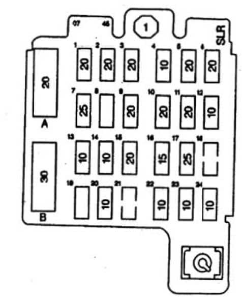
Fuse box diagram
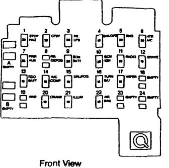
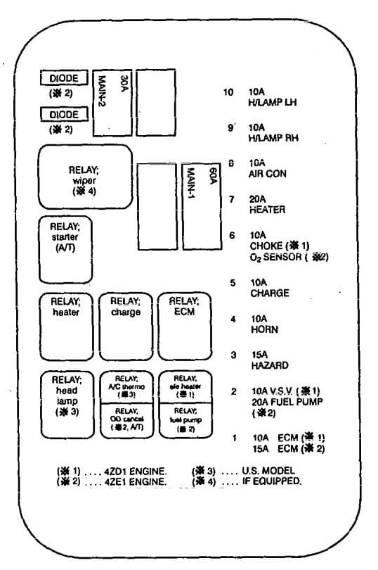
Front View
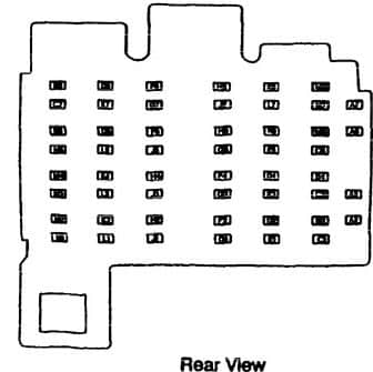
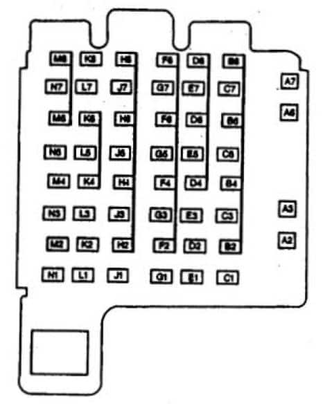
Rear View
| Fuse/Circuit Breaker | Rating | Function |
| ECM BAT Fuse 9 | 20 | • Fuel Pump Relay • Fuel Pump Switch And Encine Oil Pressure Gause Sensor (4.3 L Enaine) • Powenrain Control Module (2.2 L Enaine) • Vehicle Control Module (4.3 L Ensine) |
| ECM ION Fuse 10 | 20 | • Crankshaft Position Sensor ( 4.3 L Enainoe) • Electronic l&nition Control Module (Eiccaonic Spark Control) (4.3 L Enainel • Electronic lenition Control Module (W/0 Coil) (l.l L Enainel • Fuel Injector II I (2.2 L Enaine) • Fuel Injector II I (4.3 L Engine) • Fuel Injector II 2 (2 .2 L Engine) • Fuel Injector II l (4.3 L Encine) • Fuel Injector II 3 (2.2 L Enaine) • Fuel Injector I 3 ( 4.3 L Engine) • Fuel Injector I 4 (2.2 L Enaine) • Fuel lnje.:tor II 4 (4.3 L Engine) • Fuel lnje.:tor II S (4.3 L Enaine) • Fuel Injector It 6 ( 4.3 L Enaine) • Powenrain Control Module (2.2 L En&inc) • Vehid~ Control Module (4.3 L EnsiM) |
| RADIO Fuse 11 | 20 | • lnside Rear View Mirror • Map1Dome Lamp Reby • Radio |
| BRAKE Fuse 12 | 10 | • Cruise Control Module • Cruise Control Switch (Multi-Function Switch) • Elctronic Brake Control Module • TCC/Brake And Cruise Control Release- Switch |
| RDO BATT Fuse 13 | 10 | Radio |
| A/C COMP Fuse 14 | 10 | A/C Comprcssor Relay |
| DRL Fuse 15 | 20 | • Daytime Running Lamps Relay |
| TURN B/U Fuse 16 | 15 | • Backup Lamp Switch (Manual Transmission) • Transmission Range Switch (Park/Neutral Position And Range Switch (Park/Neutral Position And Backup Lamp Switch) • Turn Signal Lamp Flasher |
| WIPER Fuse 17 | 25 | • Washer Control Switch (Multi-Function Switch) • Windshield Wiper Pulse Control Module • Wiper Control Switch (Multi-Function Switch) |
| Fuse 18 | — | — |
| Fuse 19 | — | — |
| CRANK Fuse 20 | 10 | • Clucht Pedal Position And Cruise Control Shutoff/Switch • Supplemental Restraint Diagnostic Energy Reserve Module • Transmission Range Switch (Park/Neutral Position And Backup Lamp Switch) |
| Fuse 21 | — | — |
| AIR BAG Fuse 22 | 10 | • Supplemental Restraint Arming Sensor • Supplemental Restraint Diagnostic Energy reserve Module |
| ILLUM Fuse 23 | 10 | • Automatic Transmission Position Indicator Lamp • Heater And A/C Controller • Heater Controller • Instrument cluster • Radio • Seat Belts And Ignition Key And Lamps Alarm |
| TRANS Fuse 24 | 10 | • Automatic Transmission • Instrument Cluster • Park Pawl Actuator (Brake Transmission Shift Interlock Solenoid) |
| PWR ACCY Circuit Breaker A | 20 | • Door Lock And Side Win<low Switch, LH • Door Lock And Side Window Switch, RH • Door Lock Relay • Power Sear Acruaror Assembly, LH • Remote Control Door Lock Receiver |
| PWR WOO Circuit Breaker B | 30 | • Door Lock And Side Window Switch, LH • Door Lock And Side Window Switch, RH • Side Window Lockoutl Switch |
| STOP HAZ Fuse 1 | 20 | • Hazard Lamp Flasher • Sear Bells And Ignition Key And Lamps Alarm • TCC Brake And Cruise Control Release Switch |
| CTSY Fuse 2 | 20 | • Cargo Lamp • Cigareue lighter • Console Counesy Lamp, LF • Console Counesy Lamp, RF • Dome Lamp • Horn Relay • I/P Comparment Lamp • lnside Rear View Mirror • lnterior Lamps Control Module • Outside Remote Control Rear View Mirror Switch • Sunshade Mirror lamp, lH • Sunshade Mirror lamp, RH |
| PK LPS Fuse 3 | 20 | • Headlamp Switch • Underhood Lamp |
| GAUGES Fuse 4 | 10 | • A/C Compressor Relay • Daytime Running Lamps Control Module • Daytime Running Lamps Relay • Fuel Level Buffer Module • Supplemental Restraint Diagnostic Energy Reserve Module • Instrument Cluster • Interior Lamps Control Module • Seat Belts And Ignition Key And Lamps Alarm |
| ENG-I Fuse 5 | 20 | • Canshaft Position Sensor (4.3l Engine) • Evaporative Emission Canister Purge Solenoid Valve • Evaporative Emission Canister Vent Solenoid Valve • Exhaust Gas Recirculation Valve (4.3l Engine) • Heated Oxygen Sensor R11 Front (4.3l Engine) • Heated Oxygen Sensor Post Converter (2.2l Engine) • Heated Oxygen Sensor Post Converter (4.3l Engine) • Heated Oxygen Sensor Pre-Converter (4.3l Engine) • Heated Oxygen Sensor R11 Front (4.3l Engine) • Mass Air Flow Sensor (4.3l Engine) • Vehicle Control Module (4.3l engine) |
| HTR A/C Fuse 6 | 20 | • Air Temperature Valve Electric Actuator • Heater And A/C Controller • Heater Controller |
| PWR AUX Fuse 7 | 25 | • Auxiliary Power Outlet LH • Auxiliary Power Outlet RH • Data Link Connector |
| Fuse 8 | — | — |
WARNING: Terminal and harness assignments for individual connectors will vary depending on vehicle equipment level, model, and market.