Subaru Ascent (2018) – fuse box diagram

Subaru Ascent (2018) – fuse box diagram

Year of production: 2018

Passenger compartment fuse panel

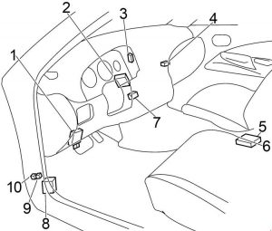
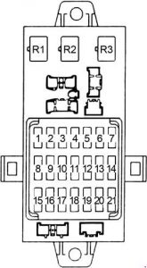
The fuse panel is located on the left side of the dashboard, below, under the cover

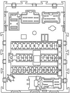
Subaru Ascent - fuse box diagram - passenger compartment
Subaru Ascent – fuse box diagram – passenger compartment
Fuse A Circuit
1
2 20A CIGAR
3 7.5A IGA-1
4 15A AUDIO NAVI
5 15A IG B-2
6
7
8 15A A/C IG
9 7.5A ACC
10 7.5A IG B-1
11
12
13 7.5A IGA-3
14 10A UNIT +B
15 7.5A METER IG
16
17 7.5A MIRROR
18 7.5A LAMP IG
19 10A IGA-2
20 10A SRS AIRBAG
21
22 15A STRG/H
23 10A DRL
24
25
26 10A BACK UP
27 15A SEAT HTR F
28 15A TRAIL
29
30
31
32 7.5A ILLUMI
33 7.5A KEY SW A
34
35
36 7.5A KEY SW B
37 7.5A STOP
38 7.5A EYE SIGHT

Engine compartment fuse box

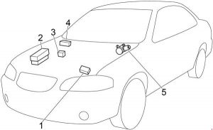
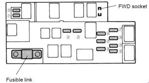
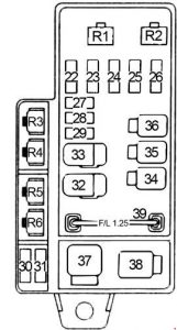
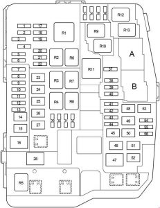
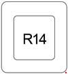
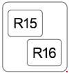
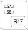
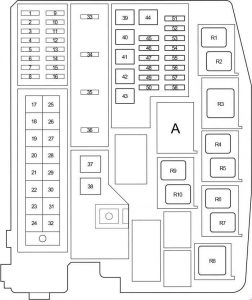
The power distribution box is located in the engine compartment

Subaru Ascent - fuse box diagram - engine compartment
Subaru Ascent – fuse box diagram – engine compartment
Fuse A Circuit
A Main fuse
1 7.5A HORN HI
2 7.5A HORN LO
3 15A H/L LO RH
4 15A H/L LO LH
5 10A DCM
6 10A H/L HI RH
7 10A H/L HI LH
8 10A TAIL
9 30A JB-B
10 25A FUEL
11 7.5A OBD
12 10A ODS
13 7.5A PU B/UP
14 15A HAZARD
15
16 10A MB-B
17 20A SOCKET
18 20A D/L
19 15A ETC
20 10A E/G2
21 7.5A CVT SSR
22 20A DI
23
24 20A O2 HTR
25
26 20A TCU
27 15A IG COIL
28 15A E/G1
29 30A BACKUP
30 15A R_S/H
31 30A VDC SOL
32 15A F. FOG
33 30A R. DEF
34 20A AUDIO
35 15A DEICER
36
37 20A BLOWER
38 20A BLOWER
39
40 15A R. WIPER
41 15A F. WASH
42 30A F. WIPER
43
44

WARNING: Terminal and harness assignments for individual connectors will vary depending on vehicle equipment level, model, and market

Mercury Mountaineer (2002 -2005) – fuse box diagram

Mercury Mountaineer (2002 -2005) – fuse box diagram

Year of production: 2002, 2003, 2004, 2005

Passenger compartment fuse panel

Mercury Mountaineer Second Generation - fuse box - passenger compartment
Mercury Mountaineer Second Generation – fuse box – passenger compartment

The fuse panel is located below the instrument panel on the driver’s side.

No. A Circuits Protected
1 30 Memory seat module, Driver power seat (’03-’05), Driver power lumbar (’05)
2 20 Heated seats (’02), Moonroof
3 20 Radio, Amplifier, Power antenna (’02), DVD
4 5 Front wiper module
5 15 Flasher relay (Turn, hazards)
6 10 Right horn (’02), Key-in-chime (’03-’05)
7 15 Heated mirrors
8 5 ’04-’05: Heated PCV (4.0L engine only)
9 Not used (spare)
10 10 Heated backlight relay coil, Heated seat module (’02), Temp blend actuator (’02), A/C clutch contact
11 20 ’03-’05: Heated seats
12 5 ’02: Foglamp switch, 4×4 module
13 5 Overdrive cancel switch, Flex fuel sender (’02-’03)
14 5 PATS module
15 5 Rear wiper module, Cluster, TPMS (’02-’03)
16 5 Power mirror, Manual climate control, TPMS
17 15 Delayed acc. coil, Battery saver, Interior lamps (front and rear), Glove compartment lamp
18 10 Left horn (’02-’03), Flexible fuel pump (’04-’05)
19 10 RCM, PAD indicator (’02)
20 5 Memory driver seat switch, Driver seat module, Body Security Module (BSM), PATS LED, Sunload sensor (’02-’03)
21 5 Instrument cluster, Compass, Flasher coil
22 10 ABS, IVD Controller
23 15 ’02-’03: Brake pedal position switch, Driver brake applied relay, Redundant cruise deactivate switch
24 15 Cigar lighter, OBD II
25 5 Mode-Temperature actuator for auxiliary climate control, Trailer tow battery charge coil, TPMS (’04-’05)
26 7.5 Reverse park aid, Brake shift interlock, Approach lamp relay coil (’02), IVD switch
27 7.5 Automatic dimming mirror, Digital transmission range sensor, Backup lamps
28 5 Radio (Start)/DVD (Start)
29 10 Digital transmission range sensor, PWR feed to fuse #28 (Start feed)
30 5 Daytime Running Lamps (DRL), Remote solenoid, DEATC climate controller, Manual climate control, Manual climate control temp blend actuator


Passenger compartment fuse panel (top side)

Mercury Mountaineer Second Generation - fuse box - passenger compartment (top side)
Mercury Mountaineer Second Generation – fuse box – passenger compartment (top side)

These relays are located on the reverse side of the passenger compartment fuse panel. To access the relays you must remove the passenger compartment fuse panel.

No. Circuits Protected
1 Flasher
2 Rear defrost
3 Delayed accessory
4 Open
5 Battery saver
6 Open
7 Open

Engine Compartment Fuse Box

Mercury Mountaineer Second Generation - fuse box - power distribution box
Mercury Mountaineer Second Generation – fuse box – power distribution box

The power distribution box is located in the engine compartment. The power distribution box contains high-current fuses that protect your vehicle’s main electrical systems from overload.

No. A Circuits Protected
1 60 PJB
2 30 BSM
3 Not used
4 30 Rear defrost
5 40 Anti-lock Brake System (ABS) pump
6 60 Delayed accessory, Power windows (’04-’05), Audio (’04-’05)
7 20 Power point #2
8 Not used
9 20 Power point #1
10 30 ABS module (valves)
11 40 PTEC (’02-’03), Powertrain Control Module (PCM) (’04-’05)
12 50 Ignition relay/Starter relay
13 40 Trailer tow battery. Trailer tow turn signals
14 10 ’02-’03: Daytime Running Lamps (DRL) (Canada)
15 15 Memory (KAPWR) (’02), Memory (PCM/DEATC/Cluster) (’03-’05), Courtesy lamps (’03-’05)
16 15 Headlamp switch (’02-’03), Foglamp switch (’03), Park lamps (’04-’05), Autolamp parklamps (’04-’05), Front foglamps relay coil (’04-’05)
17 Not used
18 20 4×4 (v-batt 1) (’02-’03), PCM with two-speed 4×4 clutch (’04-’05)
19 20 High beam relay
20 30 Trailer electric brake module
21 30 Front wiper motor
22 20 Autolamp; Low beam
23 30 Ignition switch, PCM diode (’04-’05)
24 Not used
25 15 ’04-’05: Brake on-off
26 15 ’02-’03: Fuel pump
20 ’04-’05: Fuel pump
27 20 Trailer tow lamps, Trailer tow back-up
28 20 Horn relay
29 60 PJB
30 20 Rear wiper motor
31 Not used
32 Not used
33 30 Auxiliary blower motor
34 30 Power seats, Adjustable pedals
35 20 Rear power point (’02)
36 40 Blower motor
37 15 A/C clutch relay/Transmission
38 15 Coil on plug (’02-’03), HEGO (’04-’05), VMV (’04-’05), CMS (’04-’05), ESM (’04-’05), CVS (’04-’05)
39 15 Injectors/Fuel pump relay
40 15 PTEC power (’02-’03), PCM power (’04-’05)
41 15 HEGO (’02-’03), VMV (’02-’03), CMS (’02-’03), PTEC (’02-’03), Coil on plug (’04-’05; 4.6L engine only), Ignition coil (’04-’05; 4.0L engine only)
42 10 Right low beam
43 10 Left low beam
44 15 Front foglamps
45 5 Brake pressure switch (’02)
2 Brake pressure switch (ABS) (’03-’05)
46 20 High beams
62 30 Circuit Breaker: Delayed accessory (’02), Power windows (’03-’05)
Relay
47 Horn
48 Fuel pump
49 High beam
50 Fog lamp
51 ’02-’03: Daytime Running Lamps
52 A/C clutch
53 Trailer tow right turn
54 Trailer tow left turn
55 Blower motor
56 Starter
57 ’02-’03: PTEC
’04-’05: PCM
58 Ignition
59 ’02-’03: Driver brake applied or Daytime Running Lamps
Diode
60 PCM
61 A/C clutch

Rear Relay Box

Mercury Mountaineer Second Generation - fuse box - rear relay box
Mercury Mountaineer Second Generation – fuse box – rear relay box

The relay box is located on the rear passenger side quarter trim panel. To access this box you must remove the trim panel.

No. Circuits Protected
14 Not used
15 Trailer tow back-up lamps
16 Not used
17 Not used
18 Not used
19 Trailer tow park lamps
20 Trailer tow battery charge
21 Not used
22 ’02: Approach lamps
23 Not used
Diode
3 Not used
4 Not used

Auxiliary relay box (trailer tow)

Mercury Mountaineer Second Generation - fuse box - auxiliary relay box
Mercury Mountaineer Second Generation – fuse box – auxiliary relay box

The relay box is located on the front right fender well underneath the speed control module.

Relay Description
Relay 64 Trailer Tow (left turn)
Relay 65 Trailer Tow (right turn)
Relay 66 Not used

WARNING: Terminal and harness assignments for individual connectors will vary depending on vehicle equipment level, model, and market

Mercury Mountaineer (2006 – 2010) – fuse box diagram

Mercury Mountaineer (2006 – 2010) – fuse box diagram

Year of production: 2006, 2007, 2008, 2009, 2010

Passenger compartment fuse panel

Mercury Mountaineer Third Generation - fuse box - passenger panel
Mercury Mountaineer Third Generation – fuse box – passenger panel

The fuse panel is located below the instrument panel on the driver’s side.

No. A Protected Circuits
1 20 Moon roof, Adjustable pedals, DSM, Memory seats, Lumbar motor
2 5 Microcontroller power
3 20 Radio, Navigation amplifier, GPS module
4 10 ’07-’10: On-board diagnostic (OBD II) connector
20 ’06: On-board diagnostic (OBD II) connector
5 5 Moon roof, Door lock switch illumination (’08-’10), Auto dimming rear view mirror (’10), Rearview mirror with microphone (’08-’09)
6 20 Liftglass release motor, Door unlock/lock
7 15 Trailer stop/turn
8 15 Ignition switch power, Passive anti-theft system (PATS), Cluster
9 2 6R Transmission control module/Powertrain control module (Ignition RUN/START), Fuel pump relay
10 5 Front wiper RUN/ACC relay in power distribution box (PDB)
11 5 Radio start
12 5 Rear wiper motor RUN/ACC, Trailer battery charge relay in PDB, Radio
13 15 Heated mirror, Manual climate rear defrost indicator
14 20 Horn
15 10 Reverse lamps
16 10 Trailer reverse lamps
17 10 Restraints control module, Passenger occupancy, PAD lamp (’06-’07)
18 10 Roll Stability Control™ (RSC) switch (’10), RSC (’10), All wheel drive (AWD) module, Heated seat switches, Reverse park aid (’10)
IVD switch (’06-’09), IVD, Compass (’06-’09), Electrochromatic mirror (’06-’09), Auxiliary climate control
19 Not used
20 10 Climate control system, Brake shift, DEATC (’06-’09)
21 Not used
22 15 Brake switch, Bi-color stop lamps, High-mount brake lamp, All turn lamps
23 15 Interior lamps, Puddle lamps, Battery saver, Instrument illumination, HomeLink®
24 10 Cluster, Theft indicator light
25 15 Trailer tow park lamps
26 15 License plate/rear park lamp, Front park lamps, Manual climate
27 15 Tri-color stop lamps
28 10 Climate controls
CB1 25 Circuit Breaker: Windows

Engine Compartment Fuse Box

’06:

Mercury Mountaineer - fuse box diagram - engine compartment
Mercury Mountaineer – fuse box diagram – engine compartment

’07 – ’10:

Mercury Mountaineer - fuse box diagram - engine compartment
Mercury Mountaineer – fuse box diagram – engine compartment
Fuse/relay Ampere rating [A] Description
1 50** BATT 2 (SJB)
2 50** BATT 3 (SJB)
3 50** BATT 1 (SJB)
4 30** Fuel pump, Injectors
5 30** Third row seat (left)
6 40** IVD module
7 40** Powertrain Control Module (PCM)
8 40** Heated windshield (left)
9 40** Heated windshield (right)
10 30** Power seat (right)
11 30** Starter
12 30** Third row seat (right)
13 30** Trailer tow battery charger
14 30** Memory seats (DSM)
40** Non-memory seats
15 40** Rear defrost, Heated mirrors
16 40** Blower motor
17 30** Trailer electronic brakes
18 30** Auxiliary blower motor
19 30** Running boards
20 Not used
21 20* Rear power point
22 20* Subwoofer
23 Not used
24 10* Powertrain Control Module (PCM) KAP, CAN vent
25 20* Front power point/Cigar lighter
26 20* AWD module
27 20* 6R Transmission module
28 20* Heated seats, Power mirrors
29 20* Headlamps (right)
30 25* Rear wiper
31 15* Fog lamps
32 5* Power mirrors
33 30* IVD module
34 20* Headlamps (left)
35 10* AC clutch
36 Not used
37 30* Front wiper
38 15* 5R Transmission
39 15* PCM power
40 15* Fan clutch, PCV valve, AC clutch relay, GCC fan
41 15* SDARS/DVD
42 15* Redundant brake switch, EVMV, MAFS, HEGO, EVR, VCT1, VCT2, CMCV, CMS
43 15* Coil on plug (4.6L engine only), Coil tower (4.0L engine only)
44 15 Injectors
45A Not used
45B GCC fan relay
46A Not used
46B Not used
47 Front wiper relay
48 PCM relay
49 Fuel pump relay
50A Fog lamps relay
50B AC clutch relay
51 Not used
52 A/C clutch (diode)
53 Not used
54 Trailer battery charger relay
55 Starter relay
56 Blower relay
* Mini Fuses ** Cartridge Fuses

WARNING: Terminal and harness assignments for individual connectors will vary depending on vehicle equipment level, model, and market

Mercury Mystique (1995 – 2000) – fuse box diagram

Mercury Mystique (1995 – 2000) – fuse box diagram

Year of production: 1995, 1996, 1997, 1998, 1999, 2000

Passenger Compartment Fuse Box

Mercury Mystique - fuse box diagram - passenger compartment
Mercury Mystique – fuse box diagram – passenger compartment
No.
A
Fused component
19 7.5 ’95-’97: Heated rear view mirrors
20 10 Circuit breaker: Wiper motors
21 40 Power windows
22 7.5 ’95-’99: ABS module
23 15 Backup lamps
24 15 Brake lamps
25 20 Door locks
26 7.5 Main light
27 15 Cigar lighter
28 30 Electric seats
29 30 Rear window defrost
30 7.5 Engine management system
31 7.5 Instrument panel illumination
32 7.5 Radio
33 7.5 Parking lamps – driver’s side
34 7.5 Interior lighting/electric mirror adjustment
35 7.5 Parking lamps – passenger’s side
36 10 ’95-’98: Air bag
37 30 Heater blower motor
38 Not used
Relay
R12 Interior lighting
R13 Rear window defrost
R14 Heater blower motor
R15 Wiper motor
R16 Ignition
Diode
D2 Reverse voltage protection

Engine Compartment Fuse Box (’99-’00)

Mercury Mystique - fuse box diagram - engine compartment
Mercury Mystique – fuse box diagram – engine compartment
No.
A
Fused component
1 Not used
2 7.5 Alternator
3 20 Foglamps
4 Not used
5 Not used
6 3 EEC ignition module (memory)
7 20 Horn and hazard flasher warning system
8 Not used
9 15 Fuel pump
10 Not used
11 20 Ignition, Electronic Engine Control
12 Not used
13 20 HEGO sensor
14 7.5 ABS module
15 7.5 Low beam headlamp (passenger’s side)
16 7.5 Low beam headlamp (driver’s side)
17 7.5 High beam headlamp (passenger’s side)
18 7.5 High beam headlamp (driver’s side)
39 Not used
40 20 Ignition, light switch, central junction box
41 20 EEC relay
42 40 Central junction box (fuse 37 to blower relay)
43 Not used
44 Not used
45 60 Ignition
46 Not used
47 Not used
48 Not used
49 60 Engine cooling
50 Not used
51 60 ABS
52 60 Central junction box (central timer module, rear window defrost relay, fuses 24, 25, 27, 28, 34)
Relay
R1 Fuel pump
R2 EEC module
R3 Air conditioning
R4 Low beam
R5 High beam
R6 Horn
R7 Starter solenoid
R8 Engine cooling fan (high speed)
R9 Engine cooling fan
R10 Not used
R11 Daytime running lights
Diode
D1 Reverse voltage protection
D2 Not used

Engine Compartment Fuse Box (’95-’98)

Mercury Mystique - fuse box diagram - engine compartment
Mercury Mystique – fuse box diagram – engine compartment
No.
A
Fused component
1 80 Main power supply to vehicle electrical system
2 60 Engine cooling fan
3 60 ABS braking system, heater blower (’98)
4 20 Ignition, Daytime running lights
5 15 Foglamp
6 Not used
7 20 ’98: ABS system
30 ’95-’97: ABS system
8 30 ’95-’97: Air pump
9 20 Electronic Engine Control (EEC)
10 20 Ignition switch
11 3 EEC ignition module (memory)
12 15 Horn and hazard flasher warning system
13 20 ’98: HEGO sensor
15 ’95-’97: HEGO sensor
14 15 Electrically operated fuel pump
15 10 Low beam headlamp – (passengers side)
16 10 Low beam headlamp – (driver’s side)
17 10 High beam headlamp – (passengers side)
18 10 High beam headlamp – (driver’s side)
Relay
R1 Daytime running lights
R2 Radiator fan relay (high speed)
R3 Air conditioning
R4 Air conditioning clutch relay
R5 Radiator fan relay (low speed)
R6 Starter solenoid
R7 Horn
R8 Fuel pump
R9 Low beam headlamps
R10 High beam headlamps
R11 PCM module
Diode
D1 Reverse voltage protection

Auxiliary relays (outside of fuse boxes (’99-’00))

No.
Circuits switched
Location
R18 “One touch” switch (drivers window) Driver’s door
R22 Foglamps Wire shield on instrument panel
R23 Turn signals Steering column
R24 Panic alarm – driver’s side Door lock module bracket
R25 Panic alarm – right-hand side Door lock module bracket
R32 Hego heater control (’00) Near PCM-Module

WARNING: Terminal and harness assignments for individual connectors will vary depending on vehicle equipment level, model, and market.

Georgie Boy (1994) – fuse box diagram

Georgie Boy (1994) – fuse box diagram

Year of production: 1994

Fuse panel

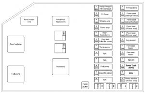
Georgie Boy - fuse box diagram
Georgie Boy – fuse box diagram
Number A Description
1 10 TV antenna
2 15 Electric step
3 1 Heated mirrors
4 10 Defroster fans
5 10 Remote mirrors
6 5 Remote mirrors
7 15 Refer (dometic)
8 20 Rear heated
9 25 Power windows
10 1 CB radio
11 3 Back-up camera
12 10 Battery disconnect
13 20 Leveler jacks
14 30 Heater
15 25 Fans
16
17 2 CB radio
18 20 Fog light
19 5 Electric step
20 15 Burgler alarm
21 20 Air horn
22 10 Service lights
23
24 20 Trunk lights
25 10 Emergency start
26 25 Cig. lighter
27 15 Spot light
28 30 Electric step
29 10 TV
30 20 TV Antenna amp
31 3 Radio memory
32 3 Radio

WARNING: Terminal and harness assignments for individual connectors will vary depending on vehicle equipment level, model, and market.

BMW 1-Series (F20/F21; 2012 – 2017) – fuse box diagram

BMW 1-Series (F20/F21; 2012 – 2017) – fuse box diagram

Year of production: 2012, 2013, 2014, 2015, 2016, 2017

Engine compartment

It is located in the right side of the engine compartment.

BMW 1-Series (F20/F21) - fuse box diagram - engine compartment
BMW 1-Series (F20/F21) – fuse box diagram – engine compartment
Number Ampere
18 15
19 10
20 5
21 5
22 7,5
23 10
24 10
25 5
26 5
27 10
28 5
29 5
30
31 7,5
32 5
33 10
34 10
35
36 40
37 40
38
39
40 15
41 10
42 5
43 15
44 5
45 5
46 5
47 5
48 10
49
50 5
51
52 7,5
53 5
54 7,5
55 5
56 5
57 40
58 30
59
60
61
62 30
63 30
64 20
65 20
65 20
66 20
67 30
68 30
69 20
70 20

Assignment of the fuses

BMW 1-Series (F20/F21) - fuse box diagram - engine compartment (assignment of fuses)
BMW 1-Series (F20/F21) – fuse box diagram – engine compartment (assignment of fuses)

BDC (Body Domain Controller)

BMW 1-Series (F20/F21) - fuse box diagram - BDC (Body Domain Controller)
BMW 1-Series (F20/F21) – fuse box diagram – BDC (Body Domain Controller)
Number Description
1 54-pin connector
2 12-pin connector
3 42-pin connector
4 54-pin connector
5 Fuses
6 Connector (1-pin, positive)
7 Relays
8 54-pin connector
9 54-pin connector
10 54-pin connector
Fuses Relays
Switching center in the steering column (SZL) Electric windows
Control panel for driver assistance systems Central locking
Lighting control panel Headlight washers
LED headlights Starter
Rear electronic module (REM) Horn
Connector OBDII, IHKA Windshield wiper at 1/2 speed
Electronic block of external door handle
Window lifter
Central locking

Luggage compartment

One unit is located on the right side, behind the sound insulation. The second – in the center, under the lining.
BMW 1-Series (F20/F21) - fuse box diagram - luggage compartment
BMW 1-Series (F20/F21) – fuse box diagram – luggage compartment
Number Ampere
80 30
82 20
83 30
85 7,5
100 15
101
102
103 5
104 5
105
106 40
107 40
108
109
110
111
112
123 20
124 20
115
116 30
117 30
118
119
120 5
121 20
122 30
123 40
124 5
125 5
126 10
127 5
128 5
130 5
131
132 5
133
134
135 5
136
137 20
138
139 20
140 20
141 20
142 30
143 5
144 10
145 15
146 5
147 5
148 5
149 7,5
150 5
151 5
152 5
153 5
154 5
155 15
156
157
158
159 5
160 20
161 20
162 20
163 20
164 20
165 20
166

Assignment of the fuses

BMW 1-Series (F20/F21) - fuse box diagram - luggage compartment (assignment of fuses)
BMW 1-Series (F20/F21) – fuse box diagram – luggage compartment (assignment of fuses)

WARNING: Terminal and harness assignments for individual connectors will vary depending on vehicle equipment level, model, and market.

Alfa Romeo 4C (2017 – 2018) – fuse box diagram

Alfa Romeo 4C (2017 – 2018) – fuse box diagram

Year of production: 2017, 2018

Dashboard Fuse Box

The dashboard fuse box is part of the Body Control Module (BCM) and is located on the passenger side under the forward passenger floor.

Cavity Fuse number Mini Fuse Description
3 F53 7,5 Instrument Panel Node
4 F38 15 Central Door Locking
5 F36 10 Diagnostic Socket, Vehicle Radio, TPMS, Alarm
6 F43 20 Bi-Directional Washer
7 F48 20 Passenger Power Window
9 F50 7,5 Airbag
10 F51 7,5 Headlamp Washer Relay, A/C Compressor Relay, High Beam Relay, Parking ECU, Vehicle Radio, Stop Lamp Switch
11 F37 7,5 Stop Light Switch, Instrument Panel Node
12 F49 5 Transmission Shifter Module, Cigar Lighter Light, Drive Style Unit, Heated Mirrors Relay
13 F31 5 Climate Control, Body Controller
14 F47 20 Driver Power Window

Engine compartment fuse box

The engine compartment fuse box is located on the left
side of the engine compartment, next to the battery.

Alfa Romeo 4C - fuse box - engine compartment
Alfa Romeo 4C – fuse box – engine compartment
Cavity Maxi Fuse Mini Fuse Description
F01 70 Body Controller
F03 20 Ignition Switch
F04 40 Anti-Lock Brake Pump
F05 20 Anti-Lock Brake Valve
F06 40 Radiator Fan – Low Speed
F07 50 Radiator Fan – High Speed
F08 20 Blower Motor
F09 5 Headlight beam switch (If Equipped)
F10 10 Horn
F11 20 Powertrain
F14 15 Alfa Twin Clutch Transmission
F15 15 Alfa Twin Clutch Transmission
F16 5 Alfa Twin Clutch Transmission, BCM
F17 10 Powertrain
F18 5 Powertrain
F19 7,5 Air Conditioning Compressor
F21 20 Fuel Pump
F22 20 Engine Control Unit Power Supply
F24 5 Anti-Lock Brake System (ABS)
F30 10 Water Pump, HVAC
F82 30 Headlamp Washer (If Equipped)
F83 40 Alfa Twin Clutch Transmission Pump
F84 5 After Run Pump
F86 15 Rear Power Outlet 12V
F88 7,5 Heated Mirrors

WARNING: Terminal and harness assignments for individual connectors will vary depending on vehicle equipment level, model, and market.

Acura RDX (2019) – fuse box diagram

Acura RDX (2019) – fuse box diagram

Year of production: 2019

Engine Compartment Fuse Box Type A

Circuit Protected Amps
1
2
3 IG1 VBSOL2 10 A
4 IG1 RR WIPER 10 A
5 IG1 VSA 10 A
6 HTR MTR 40 A
7 DBW 15 A
8 TCU 15 A
9 FI MAIN 15 A
10 STARTER CUT 30 A
11 INJ 20 A
12 HAZARD 15 A
13 TCU 2 10 A
14 TCU 3 10 A
15 FET MODULE 30 A
16 SUB FAN 30 A
17 HORN 10 A
18 BACK UP 10 A
19 STOP 7.5 A
20 FET MODULE 30 A
21 VBU 10 A
22 FRT DEICER (Not available on all models) 15 A
23 IG COIL 15 A
24 WASHER 15 A
25 MAIN FAN 30 A
26 STRLD 7.5 A
27 IGPS 10 A
28
29 R H/L LO 10 A
30 L H/L LO 10 A
31 VBACT 10 A
32 IGPS (LAF) 10 A
33

Engine Compartment Fuse Box Type B

Circuit Protected Amps
1 (50 A)
1 ABS/VSA MTR 40 A
1 F/B MAIN 2 50 A
1 F/B MAIN 60 A
1 ABS VSA FSR 40 A
1 WIPER 30 A
1 IDLE STOP 30 A
1 IDLE STOP 30 A
2
3
4 4WD (Not available on all models) (30 A)
5 IG MAIN 2 30 A
6 IG MAIN 30 A
7 H/L WASHER (Not available on all models) (30 A)
8 DR P/SEAT 3 30 A
9 EBB 40 A
10 TRL SMALL (Not available on all models) 7.5 A
11 PTG CLOSER MTR 20 A
12
13 DR P/SEAT 1 30 A
14 AS P/SEAT 2 30 A
15 AS P/SEAT 1 30 A
16 RR DEF 40 A
17 AMP 30 A (Models without seat ventilation)
40 A (Models with seat ventilation)
18 SUNSHADE 20 A
19 DR P/SEAT 2 30 A
20 AS P/SEAT 3 30 A
21 SBW 10 A
22 TRL HAZARD (Not available on all models) 7.5 A
23 BMS 10 A
24 PTG MTR 40 A

Engine Compartment Fuse Box Type C (2019)

Acura RDX - fuse box diagram - engine compartment (type C)
Acura RDX – fuse box diagram – engine compartment (type C)
Circuit Protected Amps
a MAIN 120 A
b 70 A
c R/B 1 70 A
d R/B 2 70 A
e EPS 70 A
f FET 60 A

Interior Fuse Box Type A

Circuit Protected Amps
1 BACK-UP LIGHT 10 A
2 STARTER MOTOR 10 A
3 OPTION 10 A
4
5
6 (10 A)
7
8
9 IG1 R/B 15 A
10 DR REAR DOOR LOCK 10 A
11 DR DOOR LOCK 10 A
12 AS SIDE DOOR LOCK 10 A
13 AS SIDE DOOR UNLOCK 10 A
14 DR DOOR UNLOCK 10 A
15 OPTION 2 10 A
16 SMART 10 A
17 SUNROOF 20 A
18 HEATED STRG WHEEL (Not available on all models) (10 A)
19 REAR LEFT P/W 20 A
20 SRS 10 A
21 FUEL PUMP 20 A
22 FRONT ACC SOCKET 20 A
23 LEFT H/L HI 10 A
24 RIGHT H/L HI 10 A
25 DRIVER P/W 20 A
26 DR REAR DOOR UNLOCK 10 A
27 ACCESSORY 10 A
28 PASS SRS IND (10 A)
29 PDM 10 A
30 ADS (Not available on all models) (15 A)
31 REAR RIGHT P/W 20 A
32
33 TRANSMISSION 10 A
34 ACG 10 A
35 DRL 10 A
36 A/C 10 A
37 AUDIO 15 A
38 DOOR LOCK 20 A
39 AS P/W 20 A
A REAR SEAT HEATER (Not available on all models) 20 A
B

Interior Fuse Box Type B (2019)

Circuit Protected Amps
A METER 10 A
B VSA 10 A
C OPTION 10 A
D BCM 10 A
E AUDIO 20 A
F BACKUP 10 A
G ACCESSORY (10 A)

Interior Fuse Box Type C

Circuit Protected Amps
1
2
3 A/C MG GL 10 A
4
5 FR H/SEAT 20 A

WARNING: Terminal and harness assignments for individual connectors will vary depending on vehicle equipment level, model, and market.

Mercury Grand Marquis (2003 – 2011) – fuse box diagram

Mercury Grand Marquis (2003 – 2011) – fuse box diagram

Year of production: 2003, 2004, 2005, 2006, 2007, 2008, 2009, 2010, 2011

Passenger compartment fuse panel

’03-’04:

Mercury Grand Marquis - fuse box diagram - passenger compartment
Mercury Grand Marquis – fuse box diagram – passenger compartment

’05-’11:

Mercury Grand Marquis 4th Generation - fuse box - passenger compartment
Mercury Grand Marquis 4th Generation – fuse box – passenger compartment

The fuse panel is located below and to the left of the steering wheel by the brake pedal. Remove the panel cover to access the fuses.

No. A Protected components
1 15 ’03-’04: Audio, CD changer
15 ’05-’06: Cluster, Lighting Control Module (Interior Lighting)
10 ’07-’11: Ignition (START) – Starter relay coil, DTRS
2 5 ’03-’04: Audio
10 ’05-’06: Ignition (ON) – Electronic Automatic Temperature Control (EATC) module, A/C mode switch (vehicles equipped with EATC), A/C blower relay coil (’06)
7.5 ’07-’11: Power mirrors, Door lock switches (’07-’08), Mirror switch, Keypad switch, Decklid switch, Adjustable pedal switch, Driver’s door module, Cluster
3 7.5 ’03-’04: Mirrors
10 ’05-’06: Electronic Automatic Temperature Control (EATC) module
5 ’07-’11: Ignition (START) – Audio mute
4 10 ’03-’04: Air bags
10 ’05-’06: Ignition (ON) – Anti-lock Brake System (ABS) module, Positive Crankcase Ventilation (PCV (’05)), Rear Air Suspension Module (RASM (’06)), Variable Assist Power Steering (VAPS (’06))
10 ’07-’11: Lighting control module (LCM) (switch illumination), Autolamp sensor
5 ’03-’04: Not used
10 ’05-’06: Speed control deactivation switch, Stop signal, Brake-Transmission Shift Interlock (BTSI (’05)) (column-shift transmission)
7.5 ’07-’11: Ignition (ON/ACC) – Lighting Control Module
6 15 ’03-’04: Instrument cluster warning lamps module, Overdrive control switch, Lighting Control Module (LCM), A/C clutch, Analog cluster (’04)
10 ’05-’06: Ignition (ON) – Cluster
7.5 ’07-’11: Lighting Control Module
7 10 ’03-’04: Driver’s Door Module (DDM), Premium radio
10 ’05-’06: Lighting Control Module (Park lamps, Switch illumination (’05), Corner lamps (’06))
10 ’07-’11: Ignition (ON/ACC) – Wiper module
8 25 ’03-’04: Powertrain Control Module (PCM) power relay, Coil-on plugs, Radio noise capacitor, Passive Anti-Theft System (PATS)
10 ’05: Ignition (ON) – Rear Air Suspension Module (RASM), Variable Assist Power Steering (VAPS)
10 ’06: Lighting Control Module
10 ’07-’11: Electronic Automatic Temperature Control (EATC) module (vehicles equipped with EATC only)
9 5 ’03-’04: Transmission range sensor
10 ’05-’06: Lighting Control Module (Headlamps (’05), Cornering lamps (’05), Switch illumination (’06))
7.5 ’07-’11: Ignition (ON/ACC) – Door lock switch illumination, Heated seat switch illumination, Moon roof (’07-’08), Overhead console, Radio, Antenna, Electrochromatic mirror, Window relay coil
10 10 ’03-’04: Rear window defrost, Heated mirrors
5 ’05: Ignition (ON/START) – Driver’s Door Module (DDM)
5 ’06: Ignition (START) – Audio mute
15 ’07-’11: Hazards
11 5 ’03-’04: Traction control indicator relay (ABS w/traction control only)
10 ’05: Ignition (START) – ON/ACC relay coil
10 ’06: Ignition (ON/ACC) – window relay coil
15 ’07-’11: Ignition (ON) – Turn signals
12 15 ’03-’04: Multi-function switch for turn/hazard lamps
10 ’05-’06: Ignition (START) – Starter relay coil, DTRS (’06)
15 ’07-’11: Audio
13 5 ’03-’04: Radio
10 ’05-’06: Ignition (START) – Wiper module
10 ’07-’11: Ignition (ON) – Anti-lock Brake System (ABS) module (’07-’08), Rear Air Suspension Module (RASM), Variable Assist Power Steering (VAPS) (’07-’08), Cluster
14 10 ’03-’04: Anti-lock Brake System (ABS), Instrument Cluster
10 ’05-’06: Ignition (ON) – BTSI (Floor-shift transmission)
15 ’07-’11: Adjustable pedals
15 15 ’03-’04: Speed control module, Lighting Control Module, Clock (’03), EATC blower motor relay, Door lock switch illumination, Heated seat switch, Moonroof
7.5 ’05-’06: Ignition (START) – Lighting Control Module, Door lock switch illumination, Heated seat switch illumination, Moonroof, Overhead console, Electrochromatic mirror
10 ’07-’11: Ignition (ON) – EATC module, A/C mode switch (vehicles equipped with manual A/C only), A/C blower relay coil
16 15 ’03-’04: Reversing lamps, Shift lock, DRL module, VAP Steering, Electronic day/night mirror, Overhead console, Air suspension, Climate control, Heated seat module, Speed chime module, Driver’s door module (’04), Back-up lamps (’04)
15 ’05-’06: Ignition (ON) – Turn signals
20 ’07-’08: Cigar lighter, On-board diagnostics (OBD II)
20 ’09-’11: On-board diagnostics (OBD II)
17 7.5 ’03-’04: Wiper motor
10 ’05-’06: Ignition (START) – Audio
10 ’07-’11: Ignition (ON) – A/C mode switch (vehicles equipped with manual A/C), Blend door, Heated seat modules, BTSI (Floor-shift transmission)
18 ’03-’04: Not used
10 ’05-’06: Ignition (ON) – A/C mode switch (vehicles equipped with manual A/C), Blend door, Driver’s door module (’03), Heated seat modules, Daytime Running Lamps (DRL) module (’03)
15 ’07-’11: Lighting control module (interior lighting)
19 15 ’03: Brake lamps
15 ’04: Brake lamps, Brake signal for PCM, ABS and speed control module, DDM
10 ’05-’11: Left-hand low beam, Daytime Running Lamps (DRL (’05))
20 ’03-’04: Not used
10 ’05-’11: Ignition (ON/ACC) – Back-up lamps, Anti-lock brake system (ABS (’09-’11))
21 15 ’03-’04: Lighting control module for park lamps and interior illumination, Autolamp/Sunload sensor
10 ’05-’11: Right-hand low beam, Daytime Running Lamps (DRL (’05))
22 20 ’03-’04: Speed control servo, Multi-function switch for hazard lamps, Brake on/off switch, Feed for IP fuse 19 (’04)
10 ’05-’11: Ignition (ON/ACC) – Restraint Control Module (RCM), Occupant Classification Sensor (OCS), Passenger Air bag Deactivation Indicator (PADI)
23 15 ’03-’04: EATC module, Instrument cluster, Clock (’03), Lighting control module, Interior lamps, Door lock switches
15 ’05-’11: Multi-function switch (Flash-to-pass), Lighting control module (High beams)
24 10 ’03-’04: Left-hand low beam
10 ’05-’11: Ignition (ON/ACC) – Passive Anti-Theft System (PATS) module, Powertrain Control Module (PCM) relay coil, Fuel relay coil, Ignition coil relay coil
25 15 ’03-’04: Cigar lighter
10 ’05-’06: Autolamp/Sunload sensor, Power mirrors, Door lock switches, Adjustable pedal switch, Keypad switch (’06), Decklid switch (’06), Driver’s door module
15 ’07-’11: Lighting control module (Park lamps, corner lamps, license lamps)
26 10 ’03-’04: Right-hand low beam
10 ’05: Ignition (ON/ACC) – Analog cluster, Warning lamp module, Lighting control module, Overdrive cancel switch, Rear defroster relay coil
10 ’06-’11: Ignition (ON/START) – Cluster, Lighting control module, Overdrive cancel switch, Rear defroster relay coil (’06), Traction control switch (’09-’11)
27 25 ’03-’04: Lighting control module for cornering lamps and high beam headlamps
20 ’05-’06: Cigar lighter, OBD II, Power point (’05)
’07-’11: Not used
28 20 ’03-’04: Circuit breaker: Power windows, Driver’s Door Module (’03)
10 ’05-’06: Center High-Mounted Stop Lamp (CHMSL)
7.5 ’07-’11: Brake signal, LCM (brake transmission shift interlock ((BTSI)), ABS
29 ’03-’04: Not used
15 ’05-’06: Audio
’07-’11: Not used
30 ’03-’04: Not used
15 ’05-’06: Stop lamps, MFS
’07-’11: Not used
31 ’03-’04: Not used
15 ’05-’06: Hazards
5 ’07-’11: Key in (Lighting control module)
32 ’03-’04: Not used
10 ’05-’06: Mirror heaters, Rear defroster switch indicator
’07-’11: Not used
33 ’05-’11: Not used
Relay
R1 ’05-’06: Rear defroster
’05-’11: Window

Engine Compartment Fuse Box

Mercury Grand Marquis - fuse box diagram - engine compartment
Mercury Grand Marquis – fuse box diagram – engine compartment
No. A Protected components
1 25 ’03-’04: Audio
20 ’05: Ignition switch (Key in, RUN 1, RUN 2)
25 ’06: Ignition switch (Key in, RUN 1, RUN 2), Hazards
30 ’07-’11: Ignition switch
2 20 ’03-’04: Power point
25 ’05-’06: Ignition switch (RUN/START, RUN/ACC, START)
20 ’07-’08: Moon roof
’09-’11: Not used
3 25 ’03-’04: Heated seats
10 ’05-’11: Powertrain control module (PCM) – keep alive power, Canister vent (’07-’11)
4 15 ’03-’04: Horns
20 ’05-’11: Fuel relay feed
5 20 ’03-’04: Fuel pump
10 ’05-’11: Rear Air Suspension Module (RASM), VASM (’05-’08)
6 ’03: Not used
15 ’04-’11: Alternator regulator
7 25 ’03-’04: Moonroof
30 ’05-’11: PCM relay feed
8 20 Driver’s Door Module (DDM), Door locks (’07-’08)
9 ’03-’04: Not used
15 ’05-’11: Ignition coil relay feed
10 ’03-’04: Not used
20 ’05-’11: Horn relay feed
11 20 ’03-’04: Daytime running lamps
15 ’05-’11: A/C clutch relay feed
12 ’03-’04: Not used
25 ’05-’06: Audio
20 ’07-’11: Audio (Subwoofer)
13 ’03-’04: Not used
20 ’05-’11: Instrument panel power point
14 ’03-’04: Not used
20 ’05-’11: Stop lamp switch
15 ’03-’04: Not used
20 ’05-’06: Heated seats
15 ’07-’11: Foglamps
16 ’03-’04: Not used
20 ’05: Daytime Running Lamps (DRL) module
15 ’06: Foglamps
20 ’07-’11: Heated seats
17 Not used
18 Not used
19 15 Powertrain Control Module (PCM (’03-’04)), Fuel injectors
20 15 PCM, HEGOs (’03-’04), Mass Air Flow (MAF) sensor (’05-’06), IAT (’06)
21 ’03-’04: Not used
15 ’05-’11: Powertrain loads and sensors
22 Not used
23 Not used
24 ’03-’04: Not used
5 ’05: Radio mute
’06: Radio mute
10 ’05-’11: Heated mirror, Rear defrost indicator
101 30 ’03-’04: Ignition switch, Starter motor solenoid via starter relay, IP fuses 7, 9, 12 and 14
40 ’05-’11: Blower relay feed
102 50 Cooling fan
103 40 ’03-’04: Blower motor
50 ’05-’06: Instrument panel (I/P) fuse box feed #1 (I/P fuses 19 (’04), 23, 25, 27 and 31)
50 ’07-’11: Instrument panel (I/P) fuse box feed #1, I/P fuses 10, 12, 14, 16 and 18
104 40 ’03-’04: Heated backlight relay
40 ’05-’06: Instrument panel (I/P) fuse box feed #2 (I/P fuses 1, 3, 5, 7 and 9)
50 ’07-’11: Instrument panel (I/P) fuse box feed #2 (I/P fuses 2, 4, 6, 8, 19, 21, 23 and 25)
105 30 ’03: PCM power relay
30 ’04: PCM power relay, Diagnostic connector, PDB fuses 19 and 20, A/C clutch relay, Fuel pump module relay
30 ’05-’11: Starter relay feed
106 40 Anti-lock Brake System (ABS)
107 ’03-’04: Not used
40 ’05-’11: Rear defroster relay feed
108 ’03-’04: Not used
20 ’05-’06: Moonroof
’07-’08: Not used
20 ’09-’11: Cigar lighter
109 ’03-’04: Not used
20 ’05-’11: Anti-lock brake system (ABS) module
110 ’03-’04: Not used
30 ’05-’11: Wiper module
111 Not used
112 50 ’03: Ignition switch
50 ’04: Ignition switch feed to IP fuses 4, 6, 8, 11, 13, 15, 17, 20, 22 and 28
30 ’05-’11: Air suspension compressor
113 50 ’03-’04: Feeds IP fuses 3, 5, 21, 23, 25, 27
’05-’11: Not used
114 30 ’03-’04: VAP Steering, Air suspension compressor, Instrument cluster
’05-’11: Not used
115 50 ’03-’04: Ignition switch feed to IP fuses 16 and 18
’05-’11: Not used
116 30 ’03-’04: Wipers
’05-’11: Not used
117 Not used
118 20 ’03-’04: ABS
’05-’11: Not used
401 ’03-’04: Not used
601 ’03-’04: Not used
20 ’05-’11: Circuit breaker: Power seats, Lumbar, Decklid
602 20 ’03-’04: Circuit breaker: Adjustable pedals, Power seat, Locks, Decklid, Lumbar
20 ’05-’11: Circuit breaker: Power windows relay feed (RUN/ACC)
Relay
201 ’03-’04: Horn
’05-’11: A/C clutch
202 ’03-’04: Powertrain Control Module (PCM)
’05-’11: Not used
203 ’03-’04: Fuel pump
’05-’11: Ignition coil
204 ’03-’04: A/C clutch
’05-’11: Powertrain Control Module (PCM)
205 ’03-’04: Traction control switch
’05: Not used
’06-’11: Fog lamps
206 ’03-’04: Not used
’05-’11: Fuel
207 Not used
208 ’03-’04: Moonroof
’05-’11: Not used
209 ’03-’04: Not used
’05-’11: Horn
301 ’03-’04: Blower motor
’05-’11: Starter
302 ’03-’04: Starter solenoid
’05-’11: Air compressor (Air suspension)
303 ’03-’04: Air compressor (Air suspension)
’05-’11: Blower motor
304 ’03-’04: Rear defrost
’05-’06: Power windows (RUN/ACC)
’07-’11: Rear defrost
Diode
501 ’03-’04: Powertrain Control Module (PCM)
’05-’08: A/C clutch
’09-’11: Not used
502 ’03: Not used
’04: A/C clutch
’05-’11: Powertrain Control Module (PCM)
503 ’03-’04: Not used
’05-’07: Horn, Door latch
’08-’11: Not used

WARNING: Terminal and harness assignments for individual connectors will vary depending on vehicle equipment level, model, and market.

Hyundai Tiburon (2003 – 2004) – fuse box diagram

Hyundai Tiburon (2003 – 2004) – fuse box diagram

Year of production: 2003, 2004

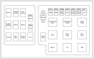
Engine compartment

Hyundai Tiburon - fuse box diagram - engine compartment
Hyundai Tiburon – fuse box diagram – engine compartment
Description A Protected component
BATT 100 Generator
BATT 50 Generator
COND 30 Condenser Fan
ECU 30 Engine Control, ECM. ATM Control
IGN 30 Ignition, Start Relay
ABS 1 30 ABS
ABS 2 30 ABS
BLOWER 30 Blower
INJ 15 Injector
SNSR 10 O2 Sensor, ECM
DRL 15 DRL
F/FOG 15 Front Fog Light
ECU 10 TCM, ECM
HORN, A/CON 15 Horn. A/Conditioner
H/LP (HI) 15 Head Light (High)
H/LP (LO) 15 Head Light (LOW)

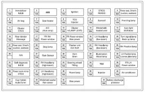
Passenger compartment

Hyundai Tiburon - fuse box diagram - passenger compartment
Hyundai Tiburon – fuse box diagram – passenger compartment
Description A Circuit protected
IG COIL 20 Ignition Coil, ECM
AMP 20 AMP. Multi Gauge Unit
B/UP LAMP 10 B/Up Lamp
A/BAG IND 10 Air Bag Indicator
A/BAG 15 Air Bag
HTD MIR 10 Outside Mirror Defroster
HAZARD 10 Hazard Warning Light
R/WIPER 15 Rear Window Wiper
TAIL-RH 10 Taillight
F/WIPER 20 Front Window Wiper
A/C SW 10 A/Conditioner
RR DEFOG 30 Rear Window Defroster
STOP 10 Stop Light
TAIL-LH 10 Tail Light
A/CON 10 A/Conditioner
ECU 10 ECM, Multi Gauge Unit, TCM
CLUSTER 10 Cluster
ROOM LP 10 Map Light, Clock, Audio
P/WINDOW 30 Power Window
T/GATE 15 Tail Gate Open
IGN 10 A/Con, A.Q.S Sensor
RR FOG 10 Rear Fog
C/LIGHT 15 C/Lighter, Outside Mirror
S/ROOF 15 Sunroof
S/HTR 20 Seat Warmer
ABS 10 ABS. TCS
AUDIO 10 Audio, Clock

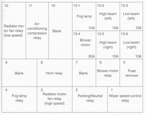
WARNING: Terminal and harness assignments for individual connectors will vary depending on vehicle equipment level, model, and market.