Ford F-150 Lightning (2022 – 2024) – fuse and relay box diagram

Ford F-150 Lightning (2022 – 2024) – fuse and relay box diagram

Year of production: 2022, 2023, 2024

The Ford F-150 Lightning, a battery-electric pickup truck, has been available from 2022 to the present. In this guide, you’ll find fuse box diagrams for the 2022, 2023 and 2024 Ford F-150 Lightning models, along with details on the locations of the fuse panels inside the vehicle and the assignment of each fuse (fuse layout).


Identifying fuse type
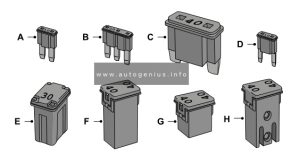
Identifying fuse type


  1. Micro 2
  2. Micro 3
  3. Maxi
  4. Mini
  5. M Case
  6. J Case
  7. J Case Low Profile
  8. Slotted M Case


Passenger Compartment Fuse Box

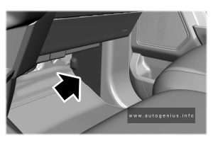
Fuse Box Location

The fuse panel is in the right-hand side of the passenger footwell behind a trim panel.
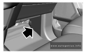
Ford F-150 Lightning - fuse and relay box location - passenger compartment
Ford F-150 Lightning – fuse and relay box location – passenger compartment


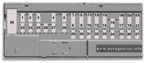
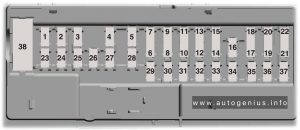
Fuse Box Diagram

Ford F-150 Lightning - fuse and relay box diagram - passenger compartment
Ford F-150 Lightning – fuse and relay box diagram – passenger compartment


Assignment of the fuses in the passenger compartment

Amps Protected Component
1 Not used.
2 10A Driver window switch-delayed accessory feed, Moonroof, Sliding backglass switch.
3 7.5A Wireless accessory charging module.
4 20A Not used (spare).
5 Not used.
6 10A Driver window switch-powered at all times.
7 10A Gearshift module.
8 5A Telematics control module, Power tailgate control module.
9 5A Inclination sensor.
10 Not used.
11 Not used.
12 7.5A Climate control module.
13 7.5A Instrument cluster, Steering column control module.
14 15A Frunk module.
15 15A Integrated control module, Accessory protocol interface module.
16 Not used.
17 7.5A Not used (spare).
18 7.5A Not used (spare).
19 5A Headlamp switch, Bluetooth low energy module.
20 5A Start switch.
21 5A Trailer brake switch.
22 5A Not used (spare).
23 30A Driver door control module.
24 30A Moonroof, Sunshade module.
25 20A Not used (spare).
26 30A Passenger door control module.
27 30A Not used (spare).
28 30A Amplifier.
29 15A Adjustable pedal switch, 12″/15″ display.
30 5A Not used (spare).
31 10A Driver status monitor, Radio transceiver module.
32 20A Radio.
Enhanced central gateway.
33 Not used.
34 30A Run/start relay.
35 5A Not used (spare).
36 15A Rear heated seat module, Steering column control module, Auto-dimming mirror.
37 20A Not used (spare).
38 30A CB Rear window switches.

Engine Compartment Fuse Box

Fuse Box Location
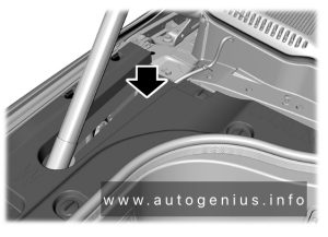
Ford F-150 Lightning - fuse and relay box location - engine compartment
Ford F-150 Lightning – fuse and relay box location – engine compartment


To access, first remove the right-side frunk cover then remove the fuse box cover:
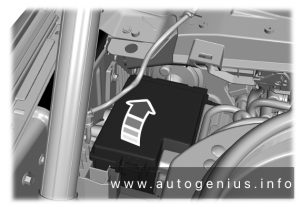
Ford F-150 Lightning - fuse and relay box location - engine compartment
Ford F-150 Lightning – fuse and relay box location – engine compartment


  1. Start at the rear edge of the right hand-side and work toward the front of the cover.
  2. Pull upward at the clip locations shown to release the clips.
  3. Remove the frunk cover.
  4. Remove the top cover.


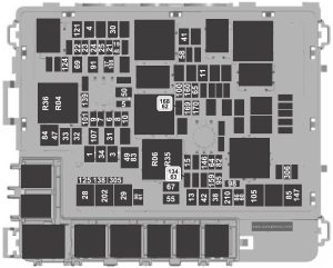
Fuse Box Diagram
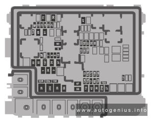
Ford F-150 Lightning - fuse and relay box diagram - engine compartment
Ford F-150 Lightning – fuse and relay box diagram – engine compartment


Assignment of the fuses in the front compartment

Amps Protected Component
1 40A Body control module.
3 40A Body control module.
5 5A Primary drive control module, Secondary drive control module.
6 25A Powertrain control module.
7 20A Powertrain control module heater cooling pump.
8 20A A/C control module, Active grille shutter, Front bumper valance motor, Electric fan relay coil.
10 10A Auxiliary power point.
13 40A Blower motor.
15 25A Horn.
17 5A Charge port status indicator.
21 10A Not used (spare).
22 10A Electronic power assist steering module.
23 10A Anti-lock brake system module.
24 10A Primary drive control module, Secondary drive control module, Powertrain control module.
25 10A Trailer camera module, Trailer tire pressure monitoring system, Trailer sway control.
27 25A Primary drive control module fluid pump.
28 50A Anti-lock brake system module.
29 50A Anti-lock brake system module.
30 40A Driver seat module.
31 30A Passenger power seat.
32 20A Power point.
33 20A Not used (spare).
34 20A Auxiliary power point.
37 30A Power tailgate module.
38 40A Climate control module.
41 25A Heated rear window.
42 30A Trailer brake control module.
46 10A Battery charger control module.
48 20A Rear heated seat module.
50 40A Heated backlite.
55 30A Trailer tow park lamps.
56 20A Trailer tow stoplamps.
58 10A Trailer tow backup lamps.
67 25A Secondary drive control module fluid pump.
69 30A Front wiper motor.
72 40A Front trunk module.
91 20A Trailer tow lighting module.
95 15A Primary drive control module.
96 20A Coolant pump.
97 10A A/C pressure and temperature sensor, High voltage battery cooling module.
99 15A Secondary drive control module, High voltage positive temperature coefficient heater.
100 25A Left-hand headlamp.
101 25A Right-hand headlamp.
107 30A Trailer tow lighting module.
116 10A Second battery charger control module.
124 5A Rain sensor.
125 10A USB smart charger 1, USB smart charger 2.
134 25A Driver multi-contour seat, Passenger multi-contour seat.
137 20A Advanced driver assistance system module, High mounted stoplamp rear video camera.
138 10A Tailgate release solenoid.
139 5A USB smart charger 3.
146 15A Battery energy control module.
159 5A Direct current/direct current converter.
160 10A Smart datalink connector.
168 15A Battery energy control module, Pedestrian sounder.
169 20A Coolant pump.
170 20A High voltage battery coolant pump.
181 5A Headlamp control module.
190 5A Not used (spare).
202 60A Body control module.
210 30A Body control module.

WARNING: Terminal and harness assignments for individual connectors will vary depending on vehicle equipment level, model, and market.

Ford F-150 (2021 – 2024) – fuse and relay box diagram

Ford F-150 (2021 – 2024) – fuse and relay box diagram

Year of production: 2021, 2022, 2023, 2024


This article focuses on the fourteenth-generation  Ford F-Series, produced from 2020 to present. It provides  fuse box diagrams for the 2021, 2022 and 2024 Ford F-150 models, along with information on the locations of the fuse panels within the vehicle and the assignment of each fuse and relay (fuse layout).

Engine compartment

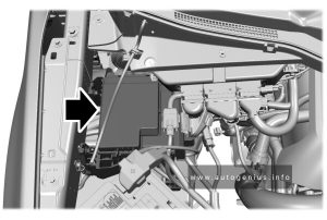
Fuse box location

Ford F-150 - fuse and relay box location - engine compartment
Ford F-150 – fuse and relay box location – engine compartment


Fuse box diagram

Version 1
Ford F-150 - fuse and relay box diagram - engine compartment
Ford F-150 – fuse and relay box diagram – engine compartment (version 1)


Assignment of the fuses in the engine compartment (version 1)

Fuse location Fuse rating Protected component
1 40A Body control module – battery power in feed 1
3 40A Body control module – battery power in feed 2
4 30A Fuel pump
5 5A Keep-alive power Powertrain control module (hybrid)
6 25A Powertrain control module power
7 20A Powertrain control module power
8 20A Powertrain control module power (hybrid)
10A Powertrain control module power (gas, diesel)
9 20A Powertrain control module power
10 20A Powertrain control module power (diesel)
11 30A Starter motor
13 40A Blower motor
15 25A Horn
19 20A Snow plow switch
Rear heated seats (gas)
21 10A Headlamp run/start feed
22 10A Electronic power assist steering
23 10A Electric brake boost
24 10A Powertrain control module (gas, hybrid), Transmission control module (diesel), Glow plug control module (diesel)
25 10A Center high-mounted stop lamp camera, Trailer camera, 2 kW inverter, 24 V alternator – run/start feed, Analog rear video camera
28 50A Electric brake boost
29 50A Electric brake boost
30 40A Driver power seat
31 30A Passenger power seat
32 20A Auxiliary power point
33 20A Auxiliary power point, USB smart charger
34 20A Auxiliary power point
37 30A Tailgate module
38 40A Climate controlled seat module, Power running boards
41 25A Power sliding back window
42 30A Trailer brake control module
47 50A Cooling fan
48 20A Rear heated seats (diesel, hybrid)
49 50A Cooling fan
50 40A Heated backlight (gas, hybrid)
55 30A Trailer tow park lamps
56 20A Trailer tow stop and turn lamps
58 10A Trailer tow backup lamps
64 25A Four-wheel drive
65 15A Transmission control module (diesel)
67 20A Transmission run/start
69 30A Left-hand windshield wiper
80 15A Not used (spare)
82 25A Four-wheel drive
83 50A Supplemental heater (diesel)
84 50A Supplemental heater (diesel)
85 50A Supplemental heater (diesel)
86 25A Selective catalytic reduction system
91 20A Trailer tow light module
95 15A Powertrain control module power (hybrid)
98 10A Powertrain control module power (hybrid), Coolant pumps (hybrid)
100 15A Left-hand headlamps
101 15A Right-hand headlamps
105 50A Active front steering
107 30A Trailer tow battery charge
121 30A Fuel filter heater (diesel)
124 5A Rain sensor module
125 10A USB smart charger
134 25A Multi-contour seats relay
138 10A Tailgate release
139 5A USB smart charger
146 15A Traction battery control module
159 5A DC/DC power (hybrid)
160 10A Smart data link control
162 7.5A Not used (spare)
168 20A Traction battery control module (hybrid)
169 10A Motor electric cool pump (hybrid)
170 10A Pedestrian alert control module (hybrid), Traction battery control module (hybrid), Electric motor cool pump (hybrid)
202 60A Body control module B+
210 30A Body control module start stop


Relay number Protected component
R04 Electronic fan relay 1
R06 Electronic fan relay 3
R35 Supplemental heater
R36 Supplemental heater


Fuse box diagram

Version 2
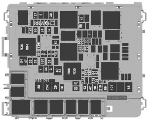
Ford F-150 - fuse and relay box diagram - engine compartment (version 2)
Ford F-150 – fuse and relay box diagram – engine compartment (version 2)


Assignment of the fuses in the engine compartment (version 2)

Item Rating Protected component
1 40A Body control module – battery power in feed 1
3 40A Body control module – battery power in feed 2
4 30A Fuel pump
5 5A Powertrain control module coil
6 25A Powertrain control module power
7 20A Powertrain control module power
8 20A Powertrain control module power (hybrid)
10A Powertrain control module power (gas, diesel, Raptor, Tremor)
9 20A Powertrain control module power
10 20A Powertrain control module power (diesel)
11 30A Starter motor
13 40A Blower motor
15 25A Horn
19 20A Snow plow switch (gas), Rear heated seats (gas, diesel, hybrid)
21 10A Headlamp run/start feed
22 10A Electronic power assist steering
23 10A Electric brake boost
24 10A Powertrain control module (gas, hybrid), Transmission control module (diesel), Glow plug control module (diesel)
25 10A Center high-mounted stop lamp camera, Trailer camera,2 kW inverter, 24 V alternator – run/start feed, Analog rear video camera
28 50A Electric brake boost
29 50A Electric brake boost
30 40A Driver power seat
31 30A Passenger power seat
32 20A Auxiliary power point
33 20A Auxiliary power point, USB smart charger
34 20A Auxiliary power point
37 30A Tailgate module
38 40A Climate controlled seat module,  Power running boards
41 25A Power sliding back window
42 30A Trailer brake control module
47 50A Cooling fan (gas, hybrid, Raptor, Tremor)
48 20A Rear heated seats (Raptor, Tremor)
49 50A Cooling fan (gas, hybrid, Raptor, Tremor)
50 40A Heated backlight (gas, hybrid)
55 30A Trailer tow park lamps
56 20A Trailer tow stop and turn lamps (4-pin connector)
58 10A Trailer tow backup lamps
60 15A Upfitter 1 relay (Raptor, Tremor)
61 15A Upfitter 2 relay (Raptor, Tremor)
62 10A Upfitter 3 relay (Raptor, Tremor)
63 10A Upfitter 4 relay (Raptor, Tremor)
64 25A Four-wheel drive
65 15A Transmission control module (diesel)
67 20A Transmission run/start
69 30A Left-hand windshield wiper
82 25A Four-wheel drive
83 50A Supplemental heater (diesel)
84 50A Supplemental heater (diesel)
85 50A Supplemental heater (diesel)
86 25A Selective catalytic reduction system (diesel)
91 20A Trailer tow light module
95 15A Powertrain control module power (hybrid)
98 10A Powertrain control module power (hybrid) Coolant pumps (hybrid)
100 15A Left-hand headlamps
101 15A Right-hand headlamps
105 50A Active front steering
107 30A Trailer tow battery charge
108 15A Spot lamps (police)
121 30A Fuel filter heater (diesel)
124 5A Rain sensor module
125 10A USB smart charger
134 25A Multi-contour seats relay (gas, diesel, hybrid)
138 10A Tailgate release
139 5A USB smart charger
146 15A Traction battery control module (hybrid)
147 40A Change air cooler fan relay (Raptor, Tremor)
159 5A DC/DC power (hybrid)
160 10A Smart data link control
168 15A Traction battery control module (hybrid)
169 10A Motor electric cool pump (hybrid)
170 10A Pedestrian alert control module (hybrid), Traction battery control module (hybrid), Electric motor cool pump (hybrid)
202 60A Body control module B+
210 30A Body control module start stop
305 5A Upfitter 5 relay (Raptor, Tremor)
306 5A Upfitter 6 relay (Raptor, Tremor)


Relay number Protected component
R04 Electronic fan relay 1
R06 Electronic fan relay 3
R35 Supplemental heater
R36 Supplemental heater


Body Control Module Fuse Box

Fuse box location

Ford F-150 - fuse and relay box location - body control module
Ford F-150 – fuse and relay box location – body control module


Fuse box diagram

Ford F-150 - fuse and relay box diagram - body control module
Ford F-150 – fuse and relay box diagram – body control module


Assignment of the fuses in the body control module

Fuse location Fuse rating Protected component
1 Not used
2 10A Delayed accessory feed
3 7.5A Wireless charger
4 20A Not used
5 Not used
6 10A Driver power window switch
7 10A Gear shift module
8 5A Cell phone passport module
9 5A Combined sensor module
10 Not used
11 Not used
12 7.5A Enhanced central gateway, Climate control
13 7.5A Instrument cluster, Steering column control module
14 15A Not used (spare)
15 15A Integrated control panel, SYNC
16 Not used
17 7.5A Headlamp control module
18 7.5A Not used
19 5A Headlamp switch
20 5A Passive start, Ignition switch, Key inhibit solenoid
21 5A Trailer brake switch
22 5A Not used
23 30A Driver door control module
24 30A Moonroof
25 20A Not used
26 30A Passenger door control module
27 30A Not used
28 30A Amplifier
29 15A 12 inch display
Adjustable pedals
30 5A Not used
31 10A RF receiver, Driver monitor, Terrain management switch
32 20A Audio control module
33 Not used
34 30A Run/start relay
35 5A 400 watt inverter run/start
36 15A Auto-dimming interior mirror, Rear heat seat run/start, Adaptive front steering run/start, Heated wheel (vehicles without adaptive front steering)
37 20A Advanced driver-assistance systems
38 30A circuit breaker Rear power windows


WARNING: Terminal and harness assignments for individual connectors will vary depending on vehicle equipment level, model, and market.
 

Ford F-150 (1992 – 1997) – fuse and relay box diagram

Ford F-150 (1992 – 1997) – fuse and relay box diagram

Year of production: 1992, 1993, 1993, 1994, 1995, 1996, 1997


This article focuses on the ninth-generation Ford F-Series, produced from 1992 to 1997. It provides fuse box diagrams for the 1992, 1993, 1994, 1995, 1996, and 1997 Ford F-150, F-250, and F-350 models, along with information on the locations of the fuse panels within the vehicle and the assignment of each fuse and relay (fuse layout).


Passenger Compartment Fuse Panel

Fuse box location

The fuse panel is located behind the cover to the left of the steering wheel. Remove the cover from the lower edge of the instrument panel by pulling on handle to disengage the fasteners.


Fuse box diagram

Ford F-150 - fuse and relay box diagram - passenger compartment
Ford F-150 – fuse and relay box diagram – passenger compartment


Assignment of the fuses in the instrument panel

A Description
1 30 Heater/Air conditioner blower
2 30 Wiper/Washer
8.25 Circuit breaker: Interval Wiper/Washer
3 3 Idle position switch (Diesel)
4 15 Exterior lamps;  Instrument illumination;  Trailer exterior lamp relay;  Warning buzzer/chime module
5 10 Airbag restraint
6 15 Fuel Tank Selector (Diesel Only), Air Conditioner/Heater, Remote/Keyless Entry
7 15 Turn Lamps
8 15 Courtesy Lamps. Engine Compartment Lamp, Radio Memory, Power Mirrors, Clock Memory, Speedometer Memory, Warning Chime, Sun Visor Mirror Illumination, Keyless Entry
9 15 Power point
25 Power point
10 4 Instrument illumination
11 15 Radio, Radio Display Dimmer
12 20 Circuit breaker: Electronic Shift Motor 4-wheel, Power Door Locks, Tailgate Power Window (Bronco)
30 Circuit breaker: Power Door Lock, Power Tailgate Window (Bronco), Electronic Shift Control, Power Lumbar
13 15 Stop and Hazard Lamps, Stop Sense For: Anti-lock Brakes, Speed Control, Electronic Engine Control, Brake Shift Interlock, Anti-Lock Brakes
14 20 Circuit breaker: Power Windows, Tailgate Power Window: Instrument Panel Switch
15 20 Anti-Lock Brakes
16 15 Cigarette Lighter, Generic Scan Tool
17 10 Overdrive Switch. Stop Lamp Switch, Warning Chime, Diesel Warning Lamps Display, Fuel Water Switch, Low Vacuum Warning Switch, Instrument Cluster, Electronic Shift Control, Tachometer, Gauges, Electronic Transmission
18 10 Air Bag Restraint, Automatic Day/Night Mirror, Brake Shift Interlock, Electronic Shift Module 4-wheel Drive, Overhead Console, Speedometer, Speed Control. Electronic Shift Control

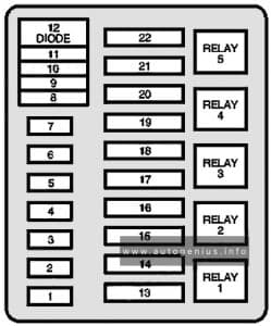
Engine compartment fuse box

Fuse box diagram

Ford F-150 - fuse and relay box diagram - engine compartment
Ford F-150 – fuse and relay box diagram – engine compartment


Assignment of the fuses in the engine compartment

A Description
1 20A Audio power
2 (15A) Fog lamps;
200A alternator (Diesel ambulance only)
3 30A Daytime running lamps (Canada only);
Headlamp flash-to-pass;
Horn
4 25A Trailer back-up lamps;
Trailer running lamps
5 15A Back-up lamps;
Daytime running lamp module (DRL) (Canada only);
Oxygen sensor heater;
Trailer battery charge relay
6 10A Trailer right-hand stop/turn lamp
7 10A Trailer left-hand stop/turn lamp
8 30A maxi Injector driver module
9 30A (Gas) / 20A (Diesel) Powertrain control system
10 20A maxi Instrument panel fuses: 15,18;
Starter relay coil
11 Not used
12 Diode Powertrain control system relay coil
13 50A maxi Instrument panel fuses: 5,9,13
14 Not used
15 50A maxi Instrument panel fuses: 1, 7;
Power distribution box: fuse 5
16 20A maxi Fuel pump feed (Gas engine)
17 50A maxi Alternator charge lamp;
Idle position switch (Diesel);
Instrument panel fuses: 2, 6, 11,14,17;
Power distribution box: fuse 22
18 30A maxi Trailer battery charge
19 40A maxi Headlamps
20 50A maxi Instrument panel fuses: 4, 8, 12,16
21 30A maxi Trailer brake feed
22 20A maxi (Gas) / 30A (Diesel) Distributor pickup (Gas engine);
Fuel line heater (Diesel);
Glow plug controller (Diesel);
Ignition coil (Gas engine);
Powertrain control system relay coil;
Thick film integrated (TFI) module (Gas engine)
Relay 1 Powertrain control system
Relay 2 Fuel pump (Gas engine);
Injector driver module (IDM relay) (Diesel)
Relay 3 Horn
Relay 4 Trailer tow lamps
Relay 5 Anti-lock brake system (ABS) pump motor

Trailer relay box

Fuse box diagram

Ford F-150 - fuse and relay box diagram - trailer relay box
Ford F-150 – fuse and relay box diagram – trailer relay box

Assignment of the fuses in the trailer relay box

Circuit Protected Size Location
Headlamps & High Beam Indicator 22 Amp Circ. Brkr. Integral with Headlamp Switch
Alternator, 95 Amp 12 Ga. Fuse Link At Starting Motor Relay (Gasoline Engine)
Alternator, 130 Amp (2) 12 Ga. Fuse Links At Starting Motor Relay (Diesel Engine)
Diesel Glow Plugs (2) 14 Ga. Fuse Links At Starting Motor Relay

WARNING: Terminal and harness assignments for individual connectors will vary depending on vehicle equipment level, model, and market.