Cupra Formentor (2020 – 2022) – fuse box and relay diagram
Year of production: 2020, 2021, 2022
The Cupra Formentor, a compact crossover, has been in production from 2020 to the present. This article provides fuse box diagrams for the 2020, 2021, and 2022 models, along with details about the locations of the fuse panels within the vehicle and the functions of each fuse (fuse layout) and relay.
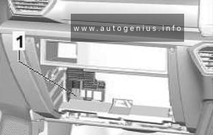
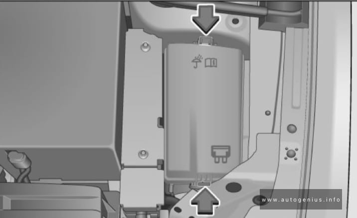
Passenger Compartment Fuse Box
Fuse Box Location
Left-hand drive vehicles: The fuse panel is behind the cover. Fold the cover down to access.
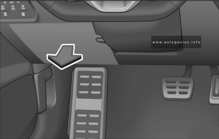
Right-hand drive vehicles: The fuses are located in the glove compartment.
Fuse Box Diagram (-SC-)
Assignment of the fuses in the instrument panel (Fuse holder C)
| № | Amps | Function/component |
|---|---|---|
| SC1 | – | – |
| SC2 | – | – |
| SC3 | 25A | Trailer detector control unit |
| SC4 | 20A | SCR, Adblue |
| SC5 | 25A | Parking lock sender Parking lock actuator |
| SC6 | 30A | Onboard supply control unit (interior light) |
| SC7 | 30A | Heated deats Heater and air conditioning controls Heater and air conditioning system control unit |
| SC8 | 20A | Sliding sunroof adjustment control unit |
| SC9 | 30A | Driver door control unit (LHD) Rear left door control unit Front passenger door control unit (RHD) |
| SC10 | – | – |
| SC11 | 15A | Trailer detector control unit |
| SC12 | 40A | Onboard supply control unit (right lights) |
| SC13 | 40A | Onboard supply control unit (central locking) |
| SC14 | 30A | Digital sound package amplifier |
| SC15 | – | – |
| SC16 | 7.5A | Airbag control unit |
| SC17 | 10A | Relay for reducing agent metering system |
| SC18 | 7.5A | Interface for entry and start system (KESSY) Control unit 2 for break-in protection Control unit 3 for break-in protection Control unit for electronic steering column lock Control unit 5 for break-in protection Control unit 4 for break-in protection Driver exterior door handle |
| SC19 | 7.5A | Emergency call module control unit and communication unit Dash panel insert |
| SC20 | 7.5A | Storage compartment with interface for mobile telephone Transmission and reception stabilisation control unit USB connection 1 |
| SC21 | 7.5A | Rear overhead view camera Control unit for overhead view camera Blind spot monitor control unit Blind Spot Monitor control unit 2 Rear lid power opening control unit |
| SC22 | – | – |
| SC23 | – | – |
| SC24 | 15A | All-wheel drive control unit |
| SC25 | 25A | Front left seat belt (LHD) Front right seat belt (RHD) |
| SC26 | 30A | Front passenger door control unit (LHD) Rear right door control unit Driver door control unit (RHD) |
| SC27 | 25A | Front left seat belt (LHD) Front right seat belt (RHD) |
| SC28 | 10A | Hybrid battery unit Pilot line connector 1 |
| SC29 | 15A | Trailer detector control unit |
| SC30 | 20A | Multimedia system Control unit 1 for information electronics |
| SC31 | 25A | Trailer detector control unit |
| SC32 | – | – |
| SC33 | – | – |
| SC34 | 30A | DC/AC converter with socket, 12V – 230V |
| SC35 | 40A | Onboard supply control unit (left lights) |
| SC36 | 40A | Fresh air blower control unit |
| SC37 | 30A | Rear lid control unit |
| SC38 | – | – |
| SC39 | 10A | Heated steering wheel Steering column electronics control unit |
| SC40 | 7.5A | Alarm horn Anti-theft alarm system horn |
| SC41 | 7.5A | Data bus diagnostic interface |
| SC42 | 7.5A | Selector mechanism Selector lever position display Control unit for electronic steering column lock |
| SC43 | 10A | Operating and display unit for rear air conditioning system Heater and air conditioning controls Heater and air conditioning system control unit Vehicle interior temperature sensor Heated rear window relay Heater and air conditioning system control unit |
| SC44 | 7.5A | Switch module 1 in centre console Operating unit for lighting Air humidity, rain and light detector sensor Front roof module Anti-theft alarm sensor Diagnostic connection |
| SC45 | 7.5A | Steering column electronics control unit |
| SC46 | 7.5A | Display unit for front information display and operating unit control unit |
| SC47 | 15A | Electronically controlled damping control unit |
| SC48 | 7.5A | USB charging socket 1 |
| SC49 | – | – |
| SC50 | – | – |
| SC51 | – | – |
| SC52 | 20A | 12V socket 12V socket 2 |
| SC53 | – | – |
| SC54 | – | – |
| SC55 | – | – |
| SC56 | – | – |
| SC57 | – | – |
| SC58 | 7.5A | Parking aid control unit Adaptive cruise control unit Front camera for driver assist systems |
| SC59 | 7.5A | Switch module 1 in centre console Relay for power sockets Air quality sensor Pressure sender for refrigerant circuit Interior mirror Reversing light switch Control unit for structure-borne sound |
| SC60 | 7.5A | Diagnostic connection |
| SC61 | 7.5A | Hybrid battery unit Power and control electronics for electric driveDNFB: Starter relay 1 Starter relay 2DNWB: Terminal 15 voltage supply relay DNNA: |
| SC62 | – | – |
| SC63 | – | – |
| SC64 | – | – |
| SC65 | 10A | Engine sound generator control unit |
| SC66 | 15A | Rear window wiper motor |
| SC67 | 30A | Amplitude modulation (AM) frequency filter Frequency modulation (FM) frequency filter in positive wire Heated rear window |
Individual fuses
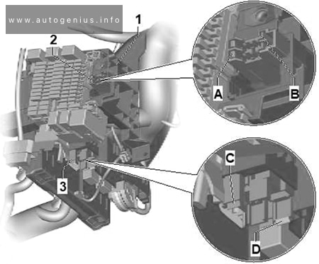
Assignment of the fuses in the instrument panel (Individual fuses)
| № | Amps | Function/component |
|---|---|---|
| A | 15A | Driver seat adjustment control unit Control unit for front right seat adjustment Control unit for front left seat adjustment |
| B | – | – |
| C | 7.5A | USB charging socket 1 USB connection 1 |
| D | – | – |
| E | – | – |
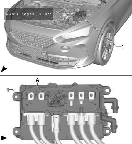
Engine Compartment Fuse Box
Fuse Box Location
Press the locking tabs to release the cover.
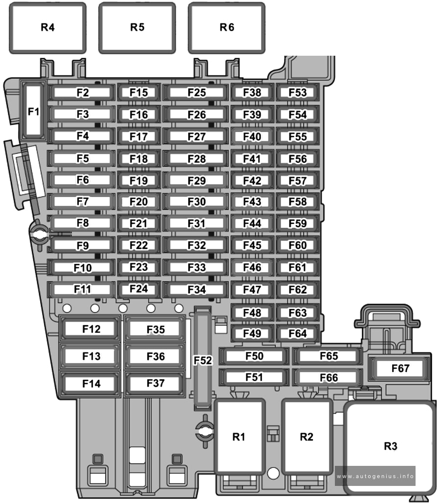
Fuse Box Diagram
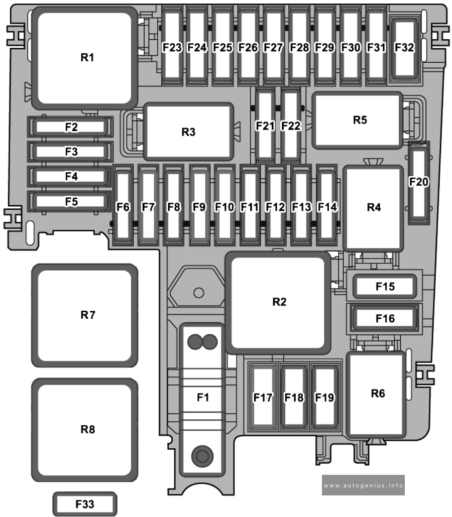
Assignment of the fuses in the engine compartment (Fuse holder B)
| № | Amps | Function/component |
|---|---|---|
| SB1 | 80A | Power steering control unit |
| SB2 | 7.5A | ABS control unit
DGEA, DNNA: |
| SB3 | 7,5A/10A/20A | Charging unit 1 for high-voltage battery Power and control electronics for electric drive Fuel pump control unitDNFB, DNNA: Engine component current supply relayDNWB: Starter relay 2 |
| SB4 | 15A | Front left headlight |
| SB5 | 15A | Front right headlight |
| SB6 | – | – |
| SB7 | 30A | Gearbox oil cooling pump |
| SB8 | 40A | Brake servo |
| SB9 | 15A | Horn relay |
| SB10 | 30A | Windscreen wiper motor |
| SB11 | 7,5A | Engine component current supply relay (PHEV Climate) |
| SB12 | 30A/15A | Mechatronic unit for dual clutch gearbox |
| SB13 | 25A | ABS control unit |
| SB14 | 20A | Engine component current supply relay (Heater) |
| SB15 | 40A | ABS control unit |
| SB16 | 50A | Mechatronic unit for dual clutch gearbox / PHEV |
| SB17 | 40A/50A | Auxiliary air heater element |
| SB18 | 40A | Auxiliary air heater element |
| SB19 | – | – |
| SB20 | 15A | Axle differential lock control unit |
| SB21 | 7.5A | Engine control unit |
| SB22 | 30A | Starter |
| SB23 | 15A | Engine control unit |
| SB24 | 7,5A/10A | Regeneration air blower Oil level and oil temperature sender Radiator fan Engine component current supply relayDGEA: Activated charcoal filter solenoid valve 1 Exhaust camshaft control valve 1 Valve for oil pressure control Inlet camshaft control valve 1DNFB: Activated charcoal filter solenoid valve 1 Intake manifold flap valve Camshaft control valve 1 Turbocharger air recirculation valve Exhaust camshaft control valve 1 Valve for oil pressure control Inlet camshaft control valve 1 DNWB: |
| SB25 | 7,5A/10A | DNFB: Cam adjustment actuator 1~8DGEA: Coolant circulation pump before power and control electronics for electric drive Heater coolant shut-off valve Coolant valve for gearbox Coolant changeover valve 1DNWB: Coolant shut-off valve Solenoid for coolant circuit |
| SB26 | 7,5A/10A | DNFB: Coolant valve for gearbox Exhaust flap control unit Exhaust flap control unit 2 Coolant circulation pumpDGEA: Charge air cooling pumpDNWB: Camshaft control valve 1 Exhaust camshaft control valve 1 Engine/motor control unit Exhaust cam actuator for cylinder 1~5 DNNA Coolant circulation pump |
| SB27 | 10A/15A | Lambda probe 1 after catalytic converter Lambda probe 1 before catalytic converter |
| SB28 | 10A/20A | 2021-2022: Ignition coil 1~4 with output stage |
| SB29 | 15A/20A/30A | Fuel pump control unit |
| SB30 | 10A | Coolant pump for low-temperature circuit 2
DGEA: DNWB: |
| SB31 | – | – |
| SB32 | – | – |
| SB33 | 40A | Auxiliary air heater element |
| R1 | Main relay (petrol) Terminal 30 voltage supply relay (diesel) |
|
| R2 | High heat output relay (diesel) Secondary air pump relay (petrol 2.0L/2.5L) |
|
| R3 | Horn relay | |
| R4 | Starter relay 1 | |
| R5 | Starter relay 2 | |
| R6 | Engine component current supply relay (petrol 2.0L/2.5L) Fuel pump relay (petrol 1.5L) Air conditioning system relay (hybrid) |
|
| R7 | Automatic glow period control unit (diesel) | |
| R8 | Low heat output relay (diesel) |
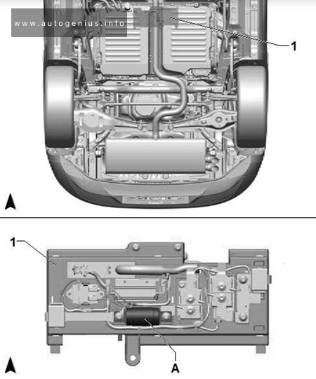
Connection and Distribution Box 2 (SX2)
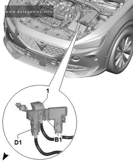
Assignment of the fuses in the engine compartment (Connection and Distribution Box 2 (SX2))
| № | Amps | Function/Component |
|---|---|---|
| B1 | – | Supply fuse holder A |
| D1 | 400A | Starter |
Fuse Holder A (Hybrid drive)
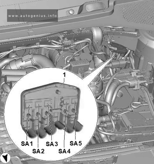
Assignment of the fuses in the engine compartment (Holder A (Hybrid drive))
| № | Amps | Function/component |
|---|---|---|
| SA1 | 150A | Fuse holder B |
| SA2 | 50A | Radiator fan |
| SA3 | 200A | Auxiliary air heater element |
| SA4 | 125A | Fuse holder C |
| SA5 | 125A | Fuse holder C |
Single fuse (JX1)
Assignment of the fuses in the engine compartment (Single fuse (JX1))
| № | Amps | Function/component |
|---|---|---|
| A | 80A | power and control electronics for electric drive |
Single fuse (SX6)
Assignment of the fuses in the engine compartment (Single fuse (SX6))
| № | Amps | Function/component |
|---|---|---|
| A | 350A | Hybrid battery unit (switching unit for high-voltage battery) |
Luggage Compartment Fuses
Fuse Holder A (2.5L petrol)
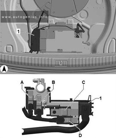
Assignment of the fuses in the luggage compartment (Holder A (2.5L petrol))
| № | Amps | Function / component |
|---|---|---|
| A | 125A | Fuse holder C, A1 |
| B | 80A | Fuse holder C, A2 |
| C | – | not assigned |
| D | 125A | Fuse 4 on fuse holder A Power steering control unit Fuse 1 on fuse holder B Fuse 2 on fuse holder B Main relay |
Fuse Holder F (Hybrid)
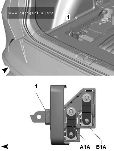
Assignment of the fuses in the luggage compartment (Holder F (Hybrid))
| № | Amps | Function/component |
|---|---|---|
| A1A | 175A | Fuse 3 on fuse holder A Relay and fuse carrier 1 |
| B1A | – | – |
WARNING: Terminal and harness assignments for individual connectors will vary depending on vehicle equipment level, model, and market.