Opel Vivaro C (2020 – 2023) – fuse and relay box diagram
Year of production: 2020, 2021, 2022, 2023
This article covers the third-generation Opel Vivaro C (Vauxhall Vivaro C), available from 2020 to the present. It includes fuse box diagrams for the 2020, 2021, 2022, and 2023 Opel Vivaro C models, provides information on the locations of the fuse panels within the vehicle, and details the assignment and layout of each fuse (fuse layout).
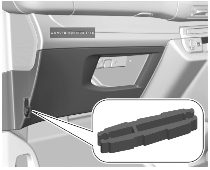
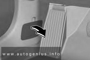
Fuse extractor
A fuse extractor may be located behind the passenger compartment fuse box cover. Unclip the cover by pulling at the top left, then right. Disengage the cover completely and turn it over.

The extractor has two sides, each side is designed for a different type of fuses.
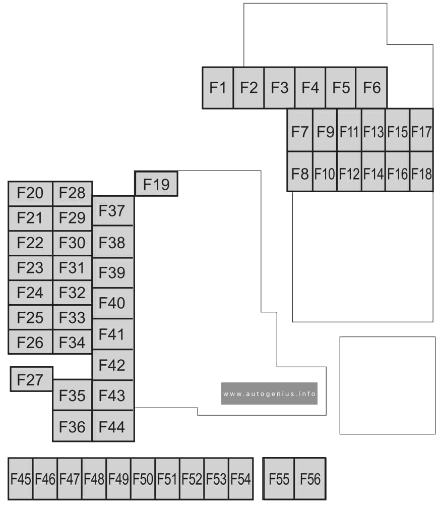
Passenger Compartment Fuse Panel
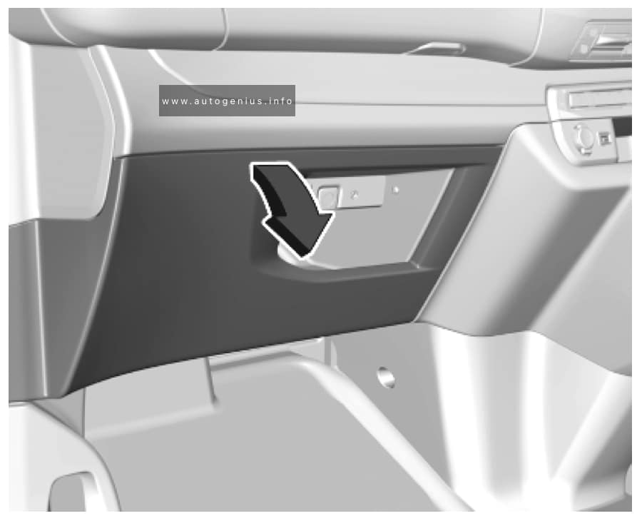
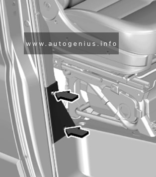
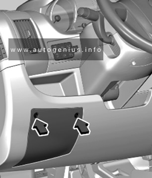
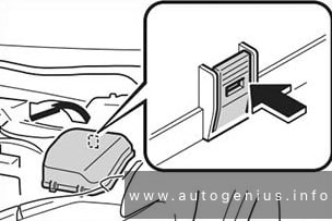
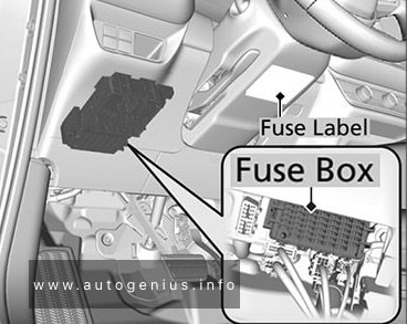
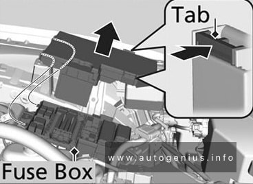
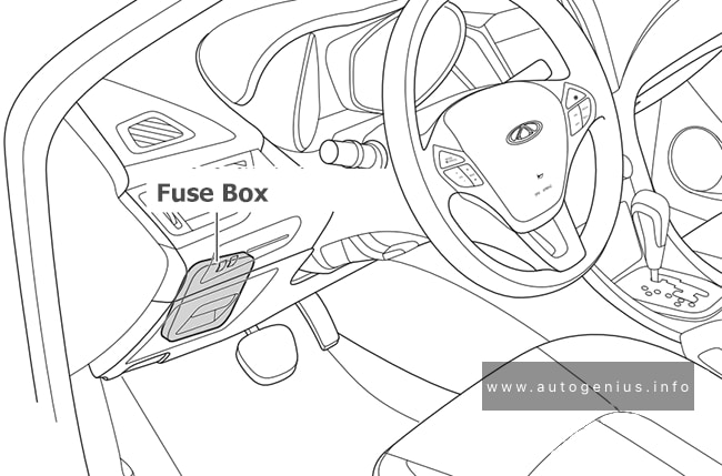
Fuse Box Location
The fuse box is located behind a cover in the instrument panel at the left side. Unclip the cover by pulling at the top left, then right. Disengage the cover completely and turn it over.

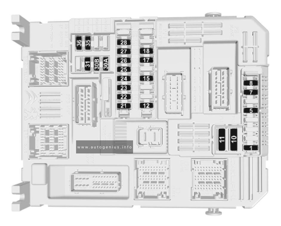
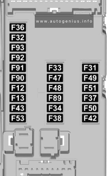
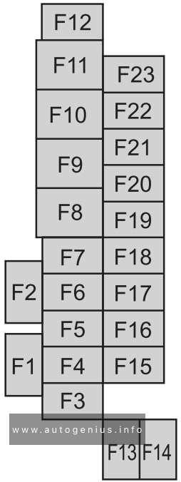
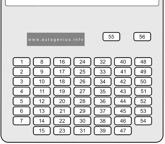
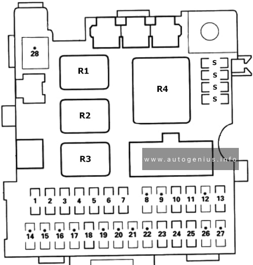
Fuse Box Diagram
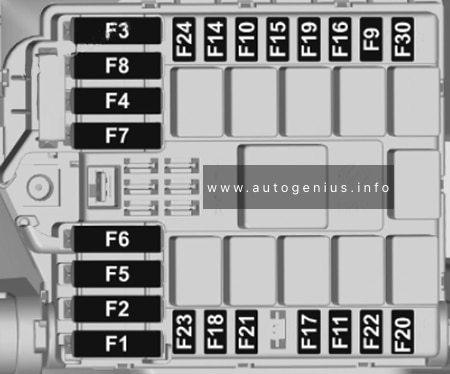
Version 1 (Eco)
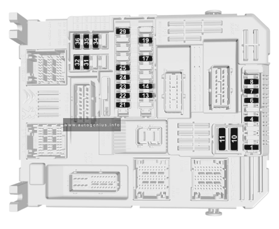
Assignment of the fuses in the instrument panel (Version 1 (Eco))
| № | Circuit |
|---|---|
| 1 | Clutch switch, power steering |
| 4 | Horn |
| 5 | Front and rear screenwash pump |
| 6 | Front and rear screenwash pump |
| 7 | Rear power outlet |
| 8 | Rear window wipers |
| 10/11 | Central locking system |
| 13 | Head-up display, climate controls, Infotainment system controls, gear selector |
| 14 | Anti-theft alarm system, telematic unit |
| 17 | Instrument cluster |
| 19 | Steering wheel controls |
| 21 | Anti-theft system or electronic key system |
| 22 | Front camera, rain and light sensor |
| 23 | Seat belt reminder |
| 24 | Parking assist, Infotainment system, rear view camera |
| 25 | Airbags |
| 29 | Infotainment system |
| 31 | Infotainment system (+ battery) |
| 32 | Front power outlet |
| 34 | Interior mirror, blind spot monitoring system, door mirror controls |
| 35 | Heated washer jets, headlight range adjustment |
| 36 | Interior lights, torch charger |
Version 2 (Full)

Assignment of the fuses in the instrument panel (Version 2 (Full))
| № | Circuit |
|---|---|
| 1 | Anti-theft system or electronic key system |
| 5 | Parking assist, Infotainment system, rear view camera |
| 7 | Rear climate controls, audio system amplifier |
| 8 | Rear window wipers |
| 10/11 | Central locking system |
| 12 | Anti-theft alarm system |
| 17 | Rear power outlet |
| 18 | Telematic unit |
| 21 | Interior lights, torch charger |
| 22 | Interior lights, glovebox light |
| 23 | Blind spot monitoring system, door mirror controls |
| 24 | Steering wheel controls |
| 25 | Headlight range adjustment |
| 26 | Seat belt reminder |
| 27 | Front camera, rain and light sensor |
| 28 | Head-up display, front climate controls, Infotainment system controls, gear selector |
| 30A or 30B | Audio system (+ battery) |
| 31 | Airbag |
| 33 | Front power outlet |
| 35 | Instrument cluster |
| 36 | Infotainment system |
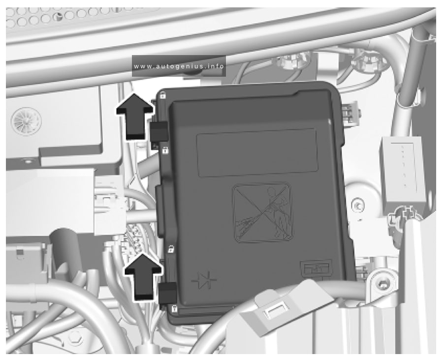
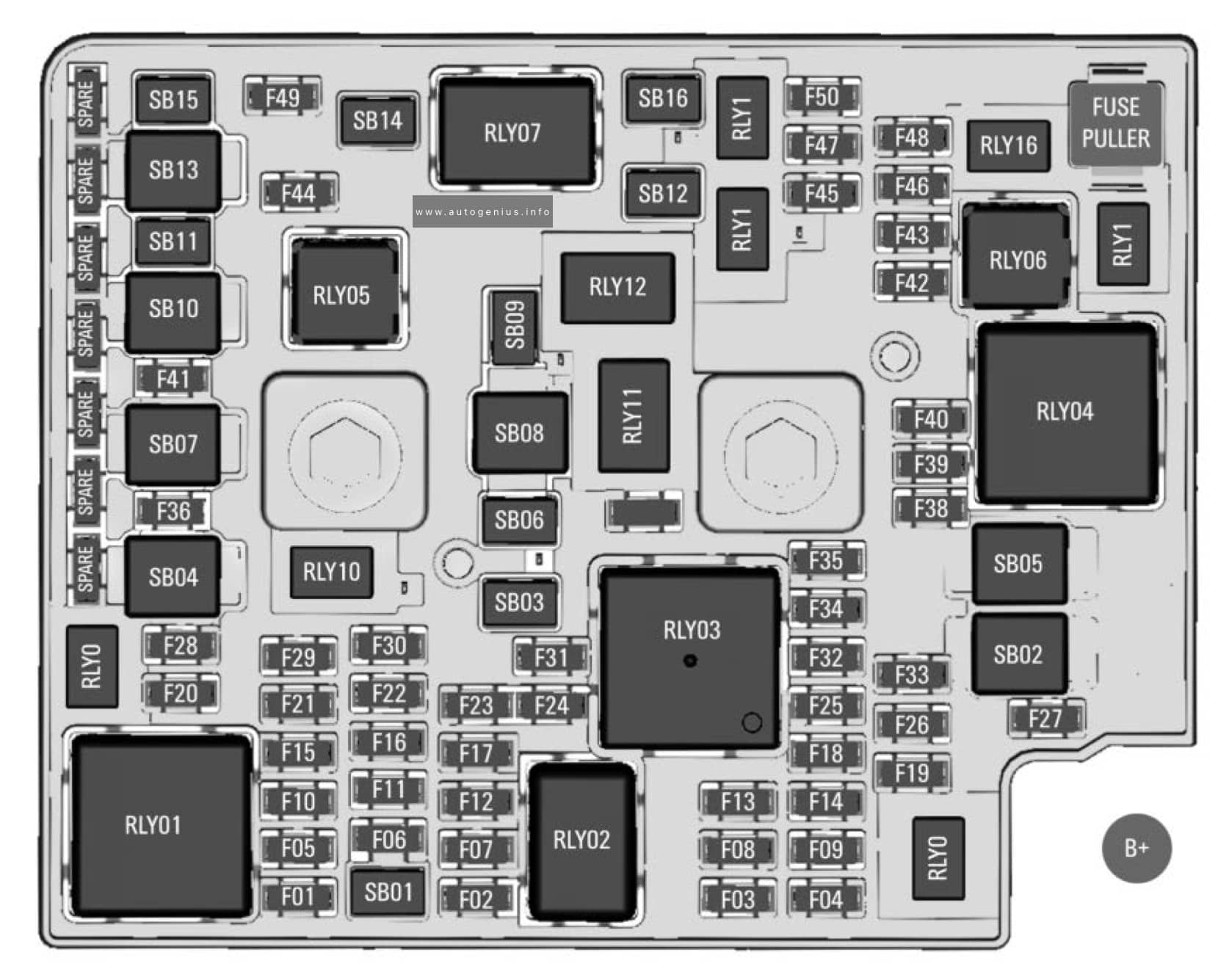
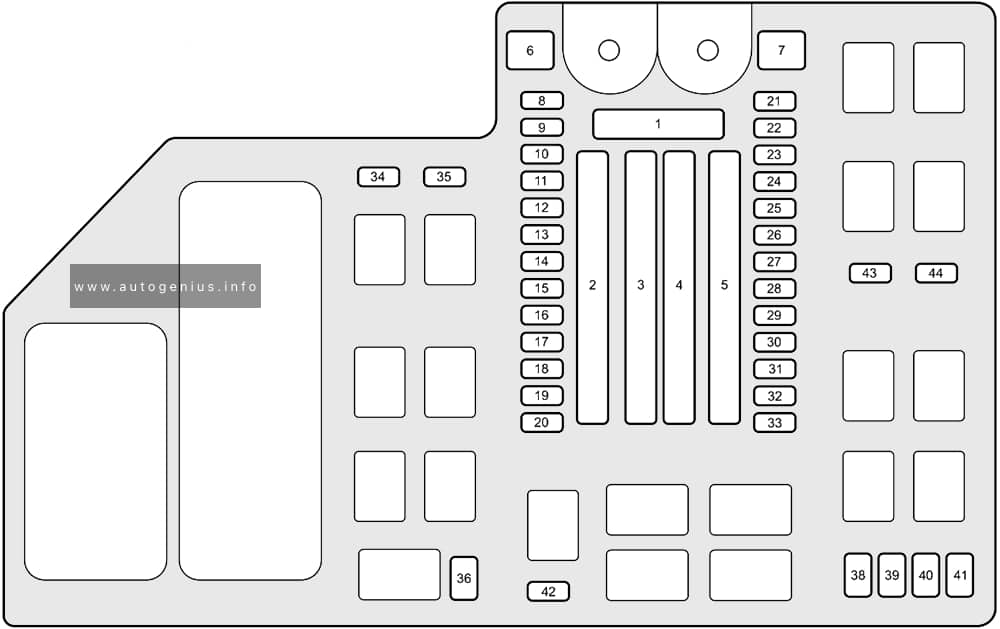
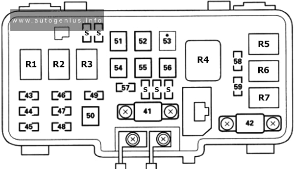
Engine Compartment Fuse Box
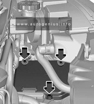
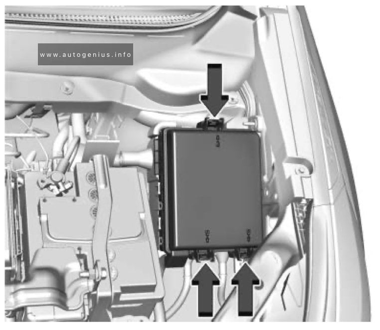
Fuse Box Location
The fuse box is in the front left of the engine compartment. Disengage the cover and remove it.

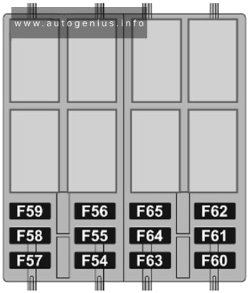
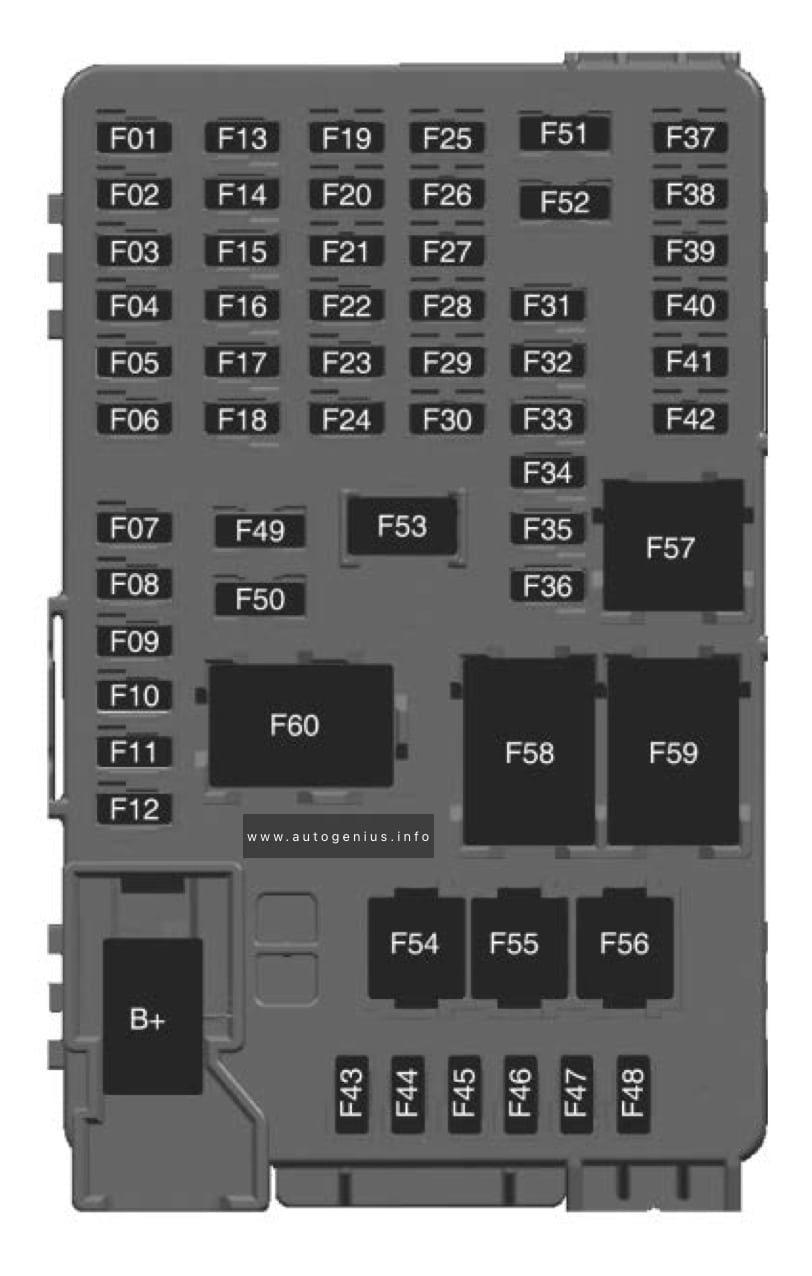
Assignment of the fuses in the engine compartment
| № | Circuit |
|---|---|
| 12 | Heated washer jets |
| 14 | Front and rear screenwash pump |
| 15 | Front radar system, electric power steering |
| 17 | Built-in systems interface |
| 19 | Front wiper motor |
| 20 | Front and rear screenwash pump |
| 21 | Headlight wash pump |
| 22 | Horn |
| 23 | Right high beam |
| 24 | Left high beam |
WARNING: Terminal and harness assignments for individual connectors will vary depending on vehicle equipment level, model, and market.