Chery Exeed TX (2019 – 2022) – fuse and relay box diagram
Year of production: 2019, 2020, 2021, 2022
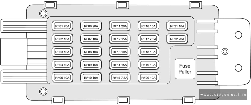
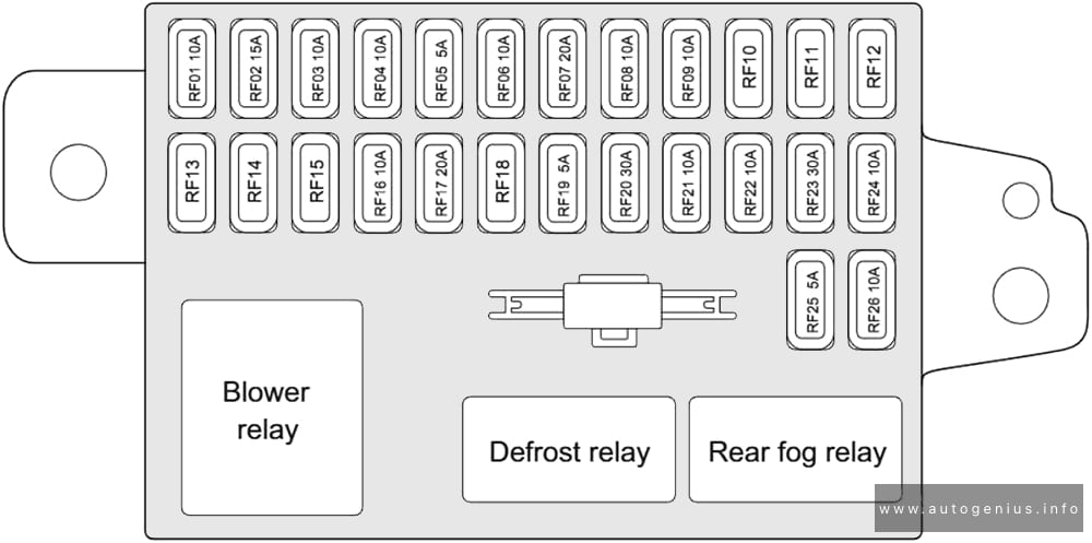
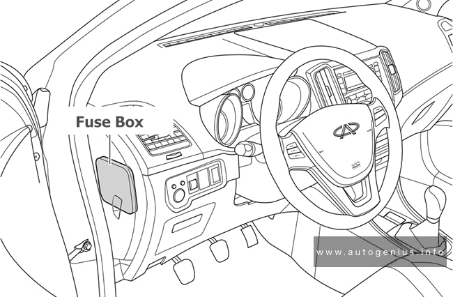
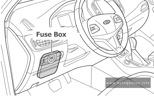
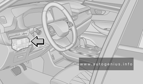
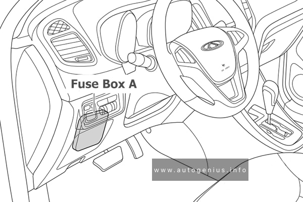
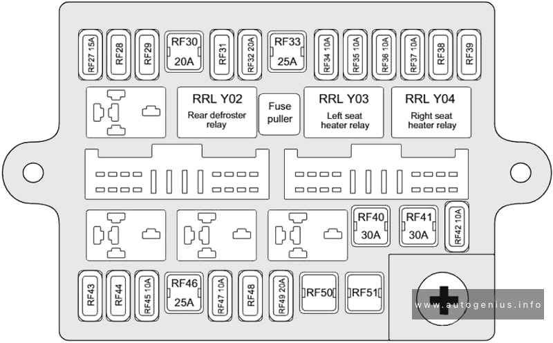
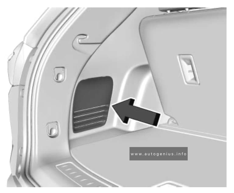
Passenger Compartment Fuse Box
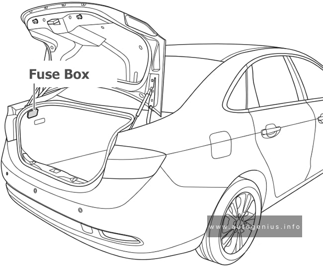
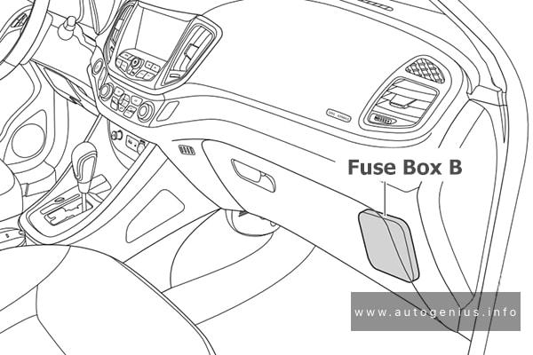
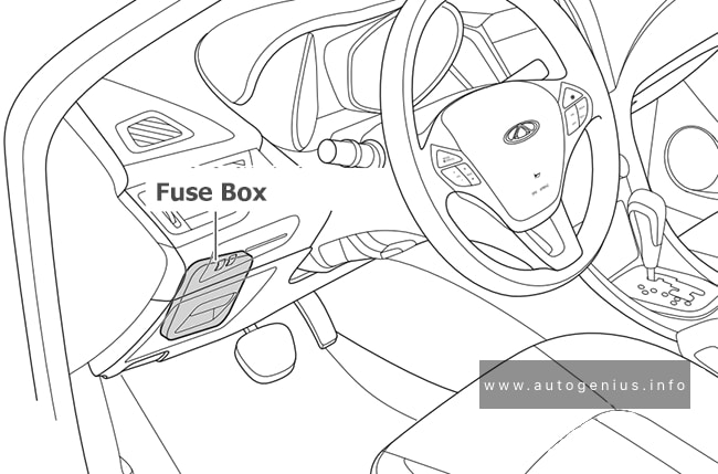
Fuse Box Location
The fuse box is located in the lower left of instrument panel.
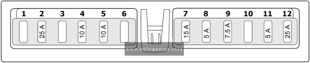
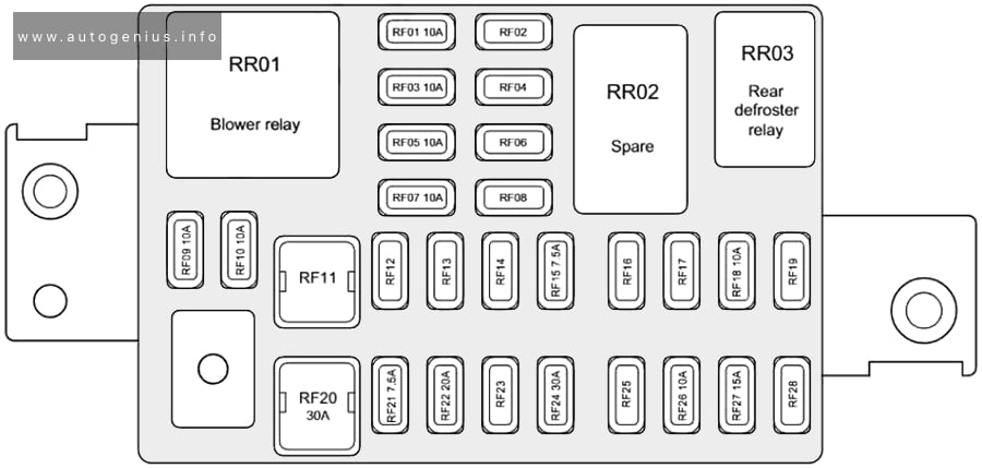
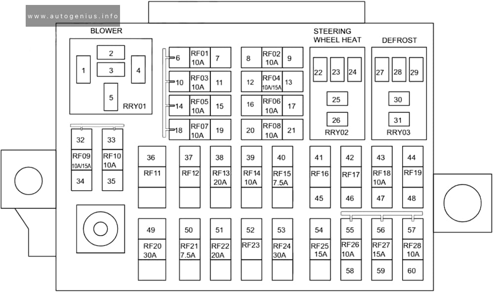
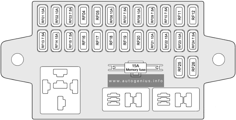
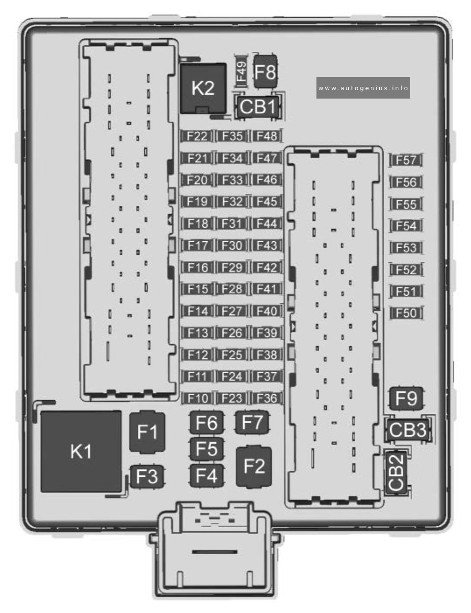
Fuse Box Diagram
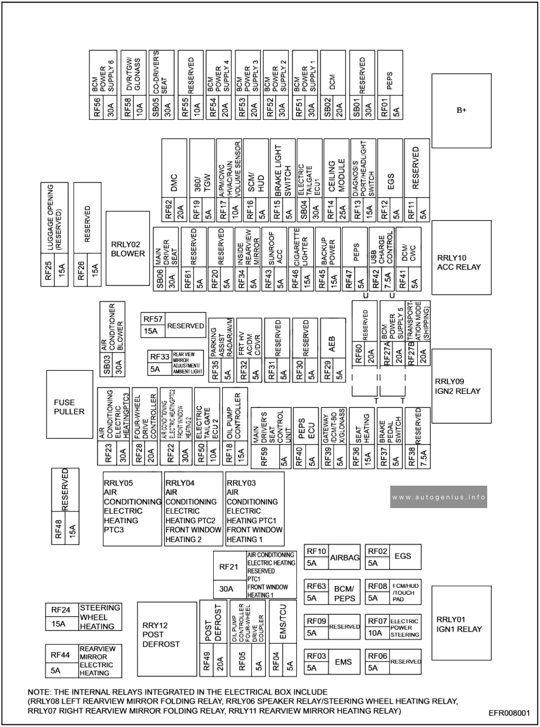
Assignment of the fuses in the instrument panel
| № | A | Description |
|---|---|---|
| RF01 | 5 | PEPS |
| RF02 | 5 | EGS |
| RF04 | 5 | EMS/TCU |
| RF05 | 5 | OIL PUMP CONTROLLER, FOUR-WHEEL DRIVE COUPLER |
| RF06 | 5 | RESERVED |
| RF07 | 10 | ELECTRIC POWER STEERING |
| RF08 | 5 | ECM/HUD/TOUCH PAD |
| RF09 | 5 | EMS |
| RF10 | 5 | AIRBAG |
| RF11 | 5 | RESERVEDRF61 |
| RF12 | 5 | EGS |
| RF13 | 15 | DIAGNOSIS PORT/HEADLIGHT SWITCH |
| RF14 | 25 | CEILING MODULE |
| RF15 | 5 | BRAKE LIGHT SWITCH |
| RF16 | 5 | SCM/HUD |
| RF17 | 10 | AIPM/CWC/HVAC/RAIN VOLUME SENSOR |
| RF18 | 15 | OIL PUMP CONTROLLER |
| RF19 | 5 | 360/TGW |
| RF20 | 5 | RESERVED |
| RF21 | 30 | AIR CONDITIONING, ELECTRIC HEATING, RESERVED, PTC1, FRONT WINDOW, HEATING 1 |
| RF22 | 30 | AIR CONDITIONING, ELECTRIC HEATING PTC2, FRONT WINDOWS HEATING 2 |
| RF23 | 30 | AIR CONDITIONING ELECTRIC HEATING PTC3 |
| RF24 | 15 | STEERING WHEEL HEATING |
| RF25 | 15 | LUGGAGE OPENING (RESERVED) |
| RF26 | 15 | RESERVED |
| RF27A | 20 | BCM, POWER SUPPLY 5 |
| RF27B | 20 | TRANSPORTATION MODE (SHIPPING) |
| RF28 | 20 | FOUR-WHEEL DRIVE CONTROLLER |
| RF29 | 5 | AEB |
| RF30 | 5 | RESERVED |
| RF31 | 5 | RESERVED |
| RF32 | 5 | FRT HV, AC/DM, C/DVR |
| RF33 | 5 | REAR VIEW MIRROR ADJUSTMENT, AMBIENT LIGHT |
| RF34 | 5 | INSIDE REARVIEW MIRROR |
| RF35 | 5 | PARKING ASSIST RADAR/AVM |
| RF36 | 15 | SEAT HEATING |
| RF37 | 5 | BRAKE PEDAL SWITCH |
| RF38 | 7,5 | RESERVED |
| RF39 | 5 | GATEWAY/DCM/T-BO, X/GLONASS |
| RF40 | 5 | PEPS ECU |
| RF41 | 5 | DCM/CWC |
| RF42 | 7,5 | USB CHARGER CONTROL |
| RF43 | 5 | SUNROOF, ACC |
| RF44 | 5 | REARVIEW MIRROR ELECTRIC HEATING |
| RF45 | 15 | BACKUP POWER |
| RF46 | 15 | CIGARETTE LIGHTER |
| RF47 | 5 | PEPS |
| RF48 | 15 | RESERVED |
| RF49 | 20 | POST DEFROST |
| RF50 | 10 | ELECTRIC TAILGATE, ECU2 |
| RF51 | 30 | BCM, POWER SUPPLY 1 |
| RF52 | 30 | BCM, POWER SUPPLY 2 |
| RF53 | 20 | BCM, POWER SUPPLY 3 |
| RF54 | 20 | BCM, POWER SUPPLY 4 |
| RF55 | 10 | RESSERVED |
| RF56 | 30 | BCM, Power supply 6 |
| RF57 | 15 | RESERVED |
| RF58 | 10 | DVR/TGW/GLONASS |
| RF59 | 5 | MAIN DRIVER’S SEAT CONTROL UNIT |
| RF60 | 20 | RESERVED |
| RF61 | 5 | RESERVED |
| RF62 | 20 | DMC |
| RF63 | 5 | BCM/PEPS |
| SB01 | 30 | RESERVED |
| SB02 | 20 | DCM |
| SB03 | 30 | AIR CONDITIONER BLOWER |
| SB04 | 30 | ELECTRIC TAILGATE, ECU1 |
| SB05 | 30 | CO-DRIVER’S SEAT |
| SB06 | 30 | MAIN DRIVER SEAT |
| RRLY01 | IGN1 RELAY | |
| RRLY02 | BLOWER | |
| RRLY03 | AIR CONDITIONING, ELECTRIC HEATING PTC1, FRONT WINDOW HEARTING 1 | |
| RRLY04 | AIR CONDITIONING, ELECTRIC HEATING PTC2, FRONT WINDOW HEATING 2 | |
| RRLY05 | AIR CONDITIONING, ELECTRIC HEATING PTC3 | |
| RRLY09 | IGN2 RELAY | |
| RRLY10 | ACC RELAY | |
| RRLY12 | POST DEFROST | |
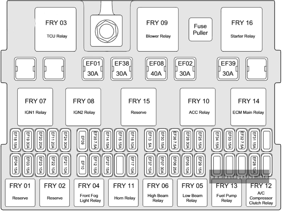
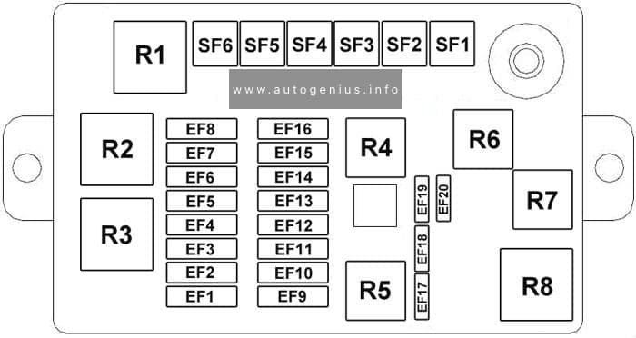
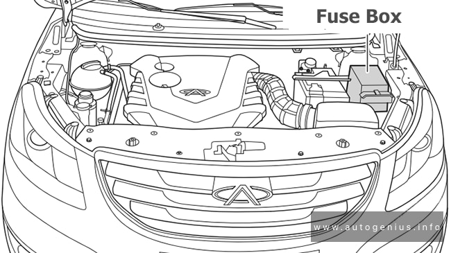
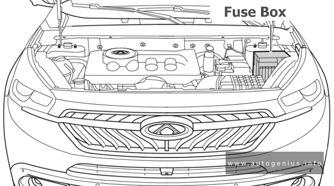
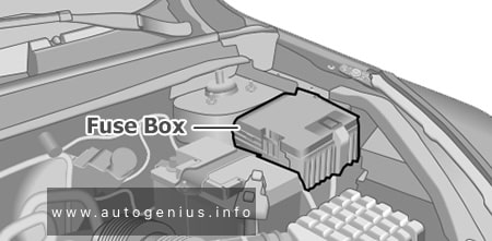
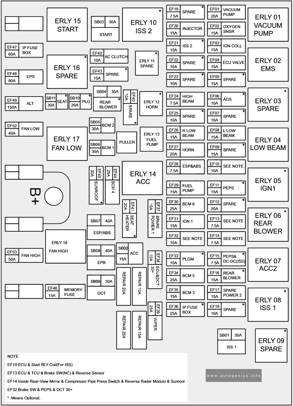
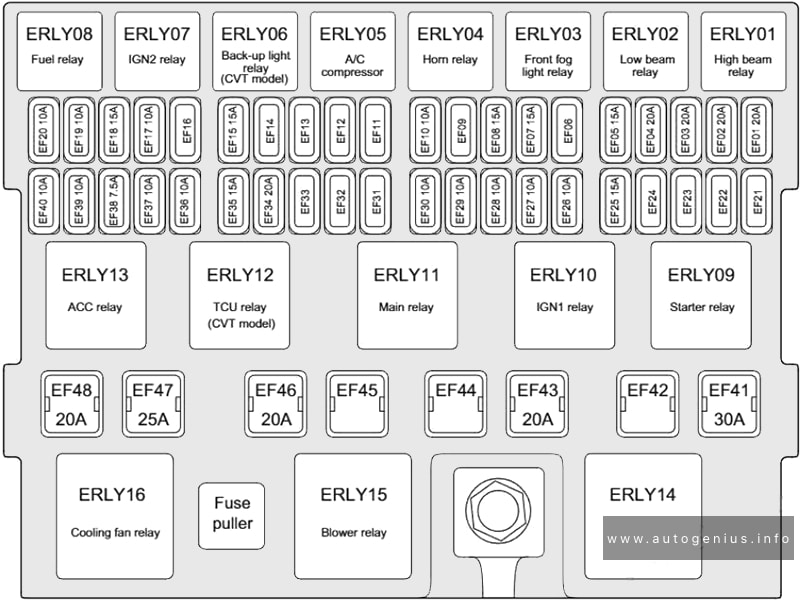
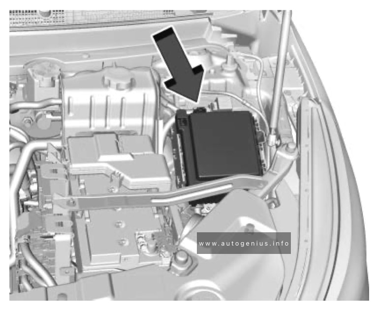
Engine compartment fuse box
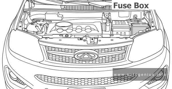
Fuse Box Location
The fuse box is located on the left side of engine compartment.
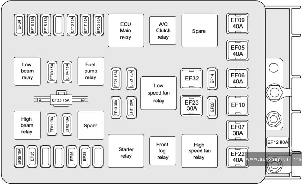
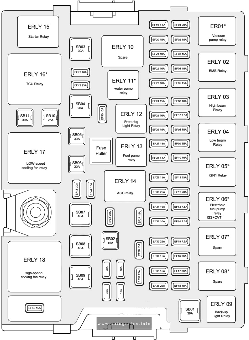
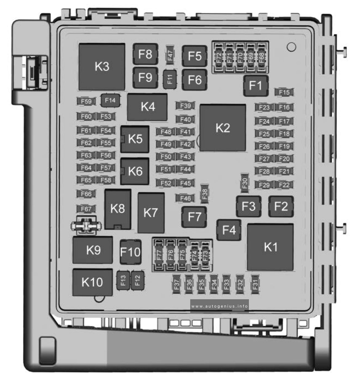
Fuse Box Diagram
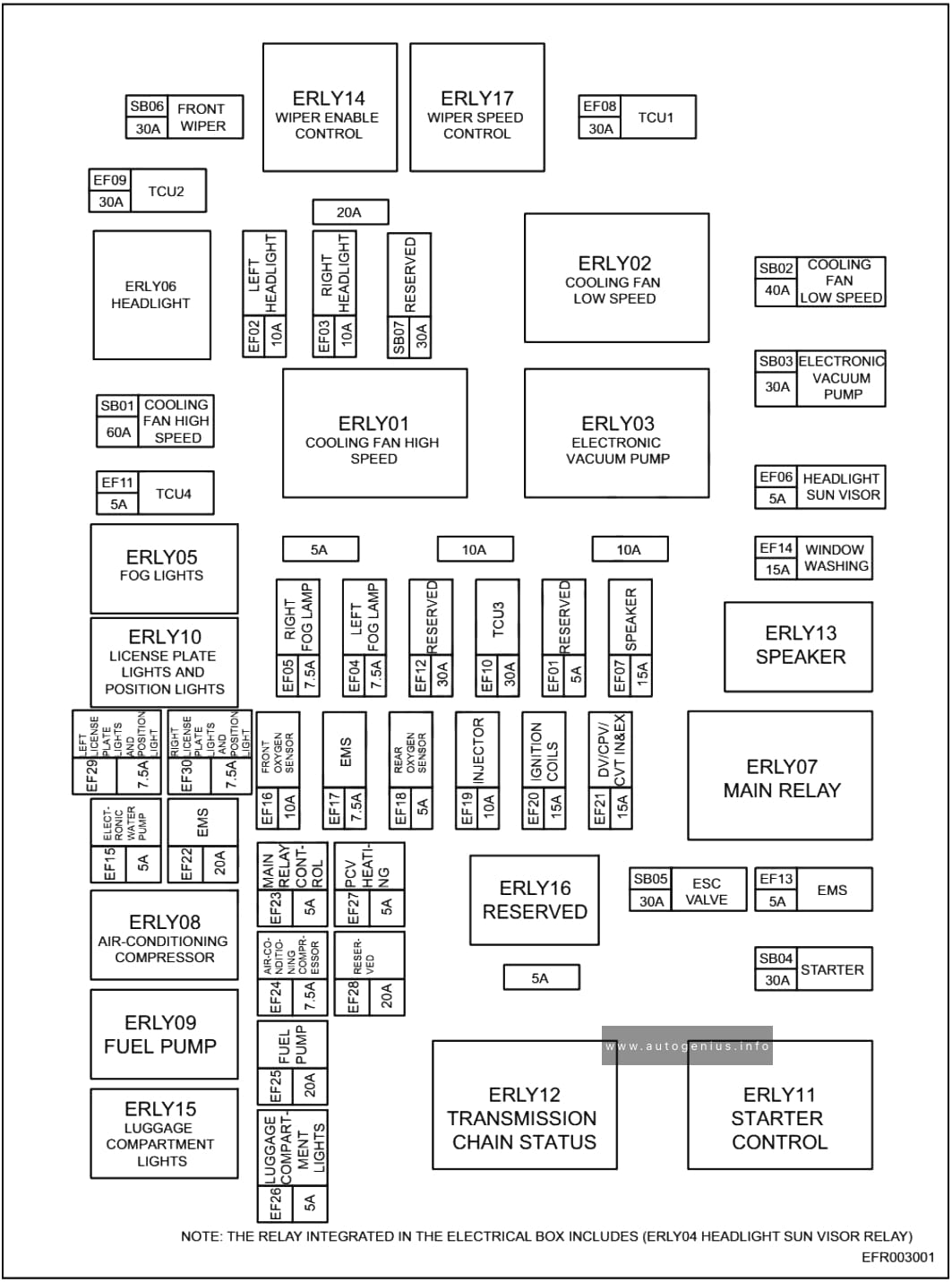
Assignment of the fuses in the engine compartment
| № | A | Description |
|---|---|---|
| EF01 | 5 | RESERVED |
| EF02 | 10 | LEFT HEADLIGHT |
| EF03 | 10 | RIGHT HEADLIGHT |
| EF04 | 7,5 | LEFT FOG LAMP |
| EF05 | 7,5 | RIGHT FOG LIGHTS |
| EF06 | 5 | HEADLIGHT SUN VISIOR |
| EF07 | 15 | SPEAKER |
| EF08 | 30 | TCU1 |
| EF09 | 30 | TCU2 |
| EF10 | 30 | TCU3 |
| EF11 | 5 | TCU4 |
| EF12 | 30 | RESERVED |
| EF14 | 15 | WINDOWS WASHING |
| EF15 | 5 | ELECTRONIC WATER PUMP |
| EF16 | 10 | FRONT OXYGEN SENSOR |
| EF17 | 7,5 | EMS |
| EF18 | 5 | REAR OXYGEN SENSOR |
| EF19 | 10 | INJECTOR |
| EF20 | 15 | IGNITION COILS |
| EF21 | 15 | DV/CPV/CVT IN&EX |
| EF22 | 20 | EMPS |
| EF23 | 5 | MAIN RELAY CONTROL |
| EF24 | 7,5 | AIR-CONDITIONING COMPRESSOR |
| EF25 | 20 | FUEL PUMP |
| EF26 | 5 | LUGGAGE COMPARTMENT LIGHTS |
| EF27 | 5 | PCV HEATING |
| EF28 | 20 | RESERVED |
| EF29 | 7,5 | LEFT LICENSE PLATE LIGHTS AND POSITION LIGHT |
| EF30 | 7,5 | RIGHT LICENSE PLATE LIGHTS AND POSITION LIGHT |
| SB01 | 60 | COOLING FAN HIGH SPEED |
| SB02 | 40 | COOLING FAN LOW SPEED |
| SB04 | 30 | STARTER |
| SB05 | 30 | ESC CALVE |
| SB06 | 30 | FRONT WIPER |
| SB07 | 30 | RESERVED |
| RRLY01 | COOLING FAN HIGH SPEED | |
| ERLY02 | COOLING FAN LOW SPEED | |
| ERLY03 | ELECTRIC VACCUM PUMP | |
| ERLY05 | FOG LIGHTS | |
| ERLY06 | HEADLIGHT | |
| ERLY07 | MAIN RELAY | |
| ERLY08 | AIR-CONDIDTIONING COMPRESSOR | |
| ERLY09 | FUEL PUMP | |
| ERLY10 | LICENSE PLATE LIGHTS AND POSITION LIGHTS | |
| ERLY11 | STARTER CONTROL | |
| ERLY12 | TRANSMISSION CHAIN STATUS | |
| ERLY13 | SPEAKER | |
| ERLY14 | WIPER ENEBLE CONTROL | |
| ERLY15 | LUGGAGE COMPARTMENT LIGHTS | |
| ERLY16 | RESERVED | |
| ERLY17 | WIPER SPEED CONTROL | |
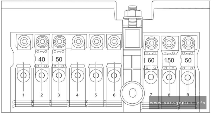
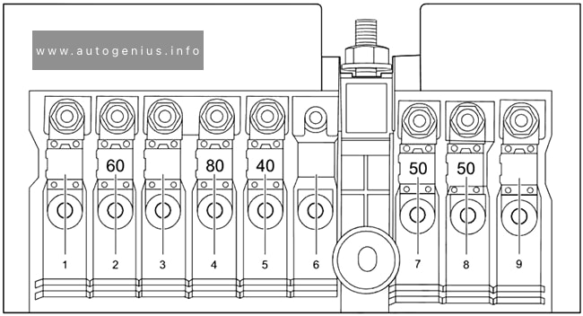
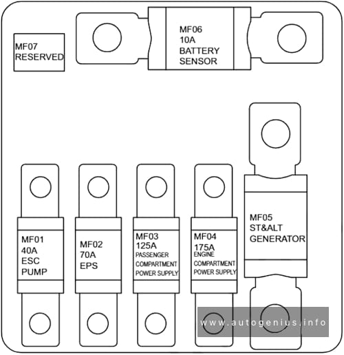
Power fuses
The power fuses are located at side of engine compartment fuse and relay box.
| № | A | Description |
|---|---|---|
| MF01 | 40 | ESC PUMP |
| MF02 | 70 | EFS |
| MF03 | 125 | PASSENGER COMPARTMENT POWER SUPPLY |
| MF04 | 175 | ENGINE COMPARTMENT POWER SUPPLY |
| MF05 | ST&ALT GENERATOR | |
| MF06 | 10 | BATTERY SENSOR |
| MF07 | RESERVED | |
| 8 | Alternator | |
| 9 | Cooling Fan |
WARNING: Terminal and harness assignments for individual connectors will vary depending on vehicle equipment level, model, and market.