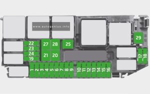
Ford Bronco (2021 – 2024) – fuse and relay box diagram

Ford Bronco (2021 – 2024) – fuse and relay box diagram

Year of production: 2021, 2022, 2023, 2024


The Ford Bronco is a legendary SUV with a storied history, spanning from its introduction in the mid-1960s to its modern revival in 2021. Known for its rugged off-road capability, distinctive design, and versatility, the Bronco has earned a devoted following over the years. The original Bronco was developed as a competitor to Jeep and became iconic in the off-roading community. After being discontinued in 1996, Ford brought back the Bronco in 2021 to great fanfare, blending modern technology with the spirit of the classic model.


Passenger Compartment

Fuse Box Location

Version 1

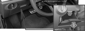
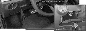
The fuse panel is located behind the panel below the glove compartment.

Ford Bronco - fuse box location - passenger compartment (version 1)
Ford Bronco – fuse and relay box location – passenger compartment (version 1)


Version 2
Ford Bronco - fuse box location - passenger compartment (version 2)
Ford Bronco – fuse and relay box location – passenger compartment (version 2)


Fuse box diagram

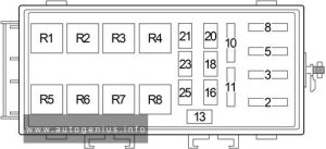
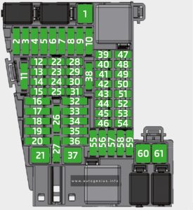
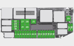
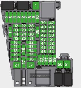
Ford Bronco - fuse box diagram - passenger compartment
Ford Bronco – fuse and relay box diagram – passenger compartment


Assignment of the fuses in the passenger compartment 

Amp. Rating Protected Component
1 Not used.
2 10A Power windows.
DC/AC inverter.
3 7.5A Exterior mirrors.
Wireless charging module.
4 20A Not used (spare).
5 Not used.
6 10A Anti-theft alarm horn.
7 10A Not used.
8 5A Not used (spare).
9 5A Not used (spare).
10 Not used.
11 Not used.
12 7.5A Climate control.
Gateway module.
13 7.5A Steering column control module.
Instrument cluster module.
14 15A Not used (spare).
15 15A Not used (spare).
16 Not used.
17 7.5A Not used (spare).
18 7.5A Not used (spare).
19 5A Ignition switch.
Headlamps.
20 5A Telematics modem.
21 5A In-vehicle temperature and humidity sensor.
22 5A Not used.
23 30A Not used (spare).
24 30A Not used (spare).
25 20A Not used (spare).
26 30A Not used (spare).
27 30A Not used (spare).
28 30A Not used (spare).
29 15A Not used (spare).
30 5A Brake on-off switch.
31 10A Terrain management switch.
Integrated control panel switch.
Driveline and chassis controls switch panel.
12 inch center display.
Radio frequency receiver module.
32 20A Audio control module.
33 Not used.
34 30A Run/start relay.
35 5A Not used (spare).
36 15A Automatic high beam.
Image processing module A.
37 20A Auto-dimming interior mirror.
Parking assist control module.
Heated steering wheel.
38 30A Not used (Circuit Breaker).

Engine Compartment Fuse Box

Fuse Box Location

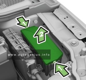
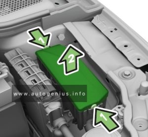
Ford Bronco - fuse box location - engine compartment
Ford Bronco – fuse and relay box location – engine compartment


Fuse Box Location

Ford Bronco - fuse box diagram - engine compartment
Ford Bronco – fuse and relay box diagram – engine compartment


Assignment of the fuses in the engine compartment 

Amp. Rating Protected Component
1 30A Body control module – battery power in feed 1.
3 30A Body control module – battery power in feed 2.
4 30A Fuel pump.
6 25A Powertrain control module power.
7 30A Powertrain components.
8 20A Powertrain components.
9 20A Ignition coils.
13 40A Blower motor control module.
16 10A Rear windshield washer.
18 30A Starter motor.
21 10A Not used (spare).
22 10A 360 degree camera module.
23 10A Anti-lock brake system run-start feed.
24 10A Powertrain control module.
Power steering module.
25 10A Blind spot information system.
Rear view camera.
Adaptive cruise control.
Driveline control module.
26 15A Transmission control module.
28 60A Anti-lock brake system valves.
29 60A Anti-lock brake system pump.
30 30A Driver power seat.
31 30A Passenger power seat.
32 20A Auxiliary power point.
33 20A Auxiliary power point.
34 20A Auxiliary power point.
36 40A 2021: 150 watt DC/AC inverter.
38 30A Heated seat module.
42 30A Trailer brake control module.
44 10A Brake on-off switch.
46 20A SYNC module.
50 40A Heated rear windshield.
54 40A Driveline control module.
55 30A Trailer tow park lamp relay.
58 20A Trailer tow backup lamps.
60 30A Upfitter switch #1.
61 15A Upfitter switch #2.
62 10A Upfitter switch #3.
63 10A Upfitter switch #4.
64 10A Upfitter switch #5.
65 10A Upfitter switch #6.
66 10A Stability bar disconnect module.
69 30A Front windshield wiper.
71 30A Rear windshield wiper.
91 40A Trailer tow light module.
100 20A Left-hand headlamps.
101 20A Right-hand headlamps.
107 30A Trailer tow battery charge.
120 10A Fuel injectors (2.7L).
124 5A Not used (spare).
125 10A USB smart charger 1.
139 5A USB smart charger 2.
140 5A Not used (spare).
141 5A Not used (spare).
146 20A Amplifier.
158 10A Stability bar disconnect module run/start.
160 10A Smart data link control.
182 60A Driver door module.
183 60A Passenger door module.
202 60A Body control module B+.
210 30A Body control module start stop.

WARNING: Terminal and harness assignments for individual connectors will vary depending on vehicle equipment level, model, and market.

RAM 1500 (2019 – 2021) – fuse and relay box diagram

RAM 1500 (2019 – 2021) – fuse and relay box diagram

Year of production: 2019, 2020, 2021


The Dodge Ram 1500 (2019–2021) represents the fifth generation of the Ram truck lineup and is renowned for its blend of rugged capability, modern technology, and refined design. In 2019, the Ram 1500 received a significant overhaul, making it more comfortable, capable, and technologically advanced, which helped it stand out in the highly competitive full-size pickup truck market against rivals like the Ford F-150 and Chevrolet Silverado.


Internal Power Distribution Center

Fuse Box Location

The Power Distribution Center is located in the engine compartment near the battery. This center contains cartridge fuses, micro fuses, relays, and circuit breakers.

RAM 1500 (2019 - 2021) - fuse box location - passenger compartment
RAM 1500 (2019 – 2021) – fuse and relay box location – passenger compartment


For access:

  1. Locate and remove the two screws from the lower portion of the fuse panel cover.
  2. After removing the screws, gently pull both the left and right side of the fuse panel cover to release the fastener clips.
  3. Reverse the procedure to reinstall the fuse panel cover.


Fuse Box Diagram

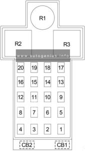
RAM 1500 (2019 - 2021) - fuse box diagram - passenger compartment
RAM 1500 (2019 – 2021) – fuse and relay box diagram – passenger compartment


Assignment of the fuses in the instrument panel fuse box (2019-2021)

Amps Description
F01 30 Trailer Tow Receptacle
F02 Spare
F03 20 Seat Heater Module – Front Passenger
F04 Spare
F05 20 eToraue Power Pack Unit (PPU) Cooling Fan Module
F06 Spare
F07 40 Central Body Controller (CBC) 3 Power Locks Module
F08 Spare
F09 Spare
F10 40 Heating Ventilation and Air Conditioning (HVAC) Blower Motor
F11 5 Output to Under-Hood Power Distribution Center (UPDC) Run Coil
F12 25 Audio Amplifier Module / Active Noise Cancellation (ANC) / Sine Wave (SW) Inverter
F13 20 Seat Heater Module – Driver
F14 15 Steering Wheel Heater Module
F15 Spare
F16 Spare
F17 20 Left Spot Lamp – If Equipped
F18 30 Sunshade Sunroof Motor
F19 Spare
F20 20 Comfort Rear Seat Module (CRSM) (Heat Rear Right)
F21 Spare
F22 Spare
F23 Spare
F24 15 Radio Frequency (RF) Hub Module / Ignition Module / Cluster Module
F25 40 Integrated Trailer Brake Module
F26 15 Cluster Cabin/Compartment Node (CCN) Module / Cyber Security Module
F27 5 Cluster Cabin/Compartment Node (CCN) Module / Secure Gateway (SGW) Module
F28 10 Occupant Restraint Control (ORC) Module
F29 20 Comfort Rear Seat Module (CRSM) (Heat Rear Left)
F30 30 Drive Train Controller Module (DTCM) / Tailgate Module
F31 30 Central Body Controller (CBC) 1 Interior Light Module
F32 20 Right Spot Lamp – If Equipped
F33 10 Overhead Console / 911 Switch / Assist Switch / Heads Up Display (HUD)
F34 15 Front & Rear Ventilated Seat Motor
F35 10 Inverter Module / Sunshade Sunroof Motor / Dual Sunroof Motor / USB Charge Only
F36 40 Central Body Controller (CBC) 2 Exterior Light 1
F37 Spare
F38 Spare
F39 Spare
F40 20 Dome Pursuit Vehicle — If Equipped
F41A / F41B 15 Lumbar Support & Pass Switch / Integrated Center Stack (ICS) Switch Bank Module / HVAC Ctrl / Bank Upper Switch / Steering Control Module
F42A / F42B 10 Transfer Case Switch Module (TCSM) / Shift bv Wire Module (SBW) / Electric Park Brake Switch / Overhead Console (OHC) Switch / E-Call / Bank 3 Switch / Seat Left & Riaht Ventilation / Trailer A&B Tire Pressure Module / Gateway Trailer Module
F43A / F43B 10 Port Diagnostics / Collision Detection (CD) Module / Front & Rear USB
F44 20 Radio/Digital Content Service Delivery (DCSD) Module / Telematics Box Module/Fleet Telematics Module (FTM)
F45 30 Door Multiplexer Module (Driver-side)
F46 30 Door Multiplexer Module (Passenger-side)
F47 Spare
F48A 10 Rear View Mirror / SW Window Passenger / Rear USB / Wireless Charging Pad Module
F49 15 Central Vision Processing Module (CVPM) / Sensor Blind SDot / HDLP AdaDtive Front Lighting Sensor (AFLS)
F50A 10 Battery Pack Control Module
F51A / F51B Spare
F52 20 Direct Battery Feed – If Equipped
F53 10 Trailer Reverse Steerina Control / Trailer Steerinq Control Knob
F54B 20 Power Outlet Center Seat
F55 25 Upfitter – If Equipped
F56 30 Network Interface Module – If Equipped
F57 20 Direct Battery Feed – If Equipped
F58 20 Direct Battery Feed – If Equipped
F59 Spare
F60 50 Inverter Module
F61 Spare
F62A / F62B 10 Intearated T railer Brakina (ITBM) / Occupant Class Mod / IAIR Suspension Mod / HVAC Sensor In-Car Temp Module / Rear Coolant Temp / Parktronic System (PTS) / Intearated Relay Ctrl Mod (IRCM) / HRLS / Gateway Trailer TPMS Module
F63 Spare
F64 Spare
F65 10 Occupant Restraint Controller (ORC) Module
F66 10 Run Accessory Feed — If Equipped
CB1 25 Driver Window SW Rear PWR Windows / Overhead SW Rear Defrost
CB2 25 Driver PWR Seat / Driver Seat Memory Mod
CB3 25 Passenger Power Seat / Passenger Seat Memory Mod


External Power Distribution Center

Fuse Box Location

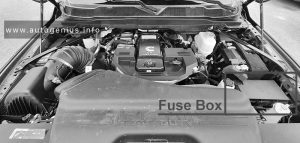
The Power Distribution Center is located in the engine compartment near the battery. This center contains cartridge fuses, micro fuses, relays, and circuit breakers. A description of each fuse and component may be stamped on the inside cover, otherwise the cavity number of each fuse is stamped on the inside cover that corresponds to the following chart.

RAM 1500 (2019 - 2021) - fuse box location - engine compartment
RAM 1500 (2019 – 2021) – fuse and relay box location – engine compartment


Fuse Box Diagram

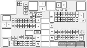
RAM 1500 (2019 - 2021) - fuse box diagram - engine compartment
RAM 1500 (2019 – 2021) – fuse and relay  box diagram – engine compartment


Assignment of the fuses in the engine compartment fuse box (2019-2021)

Amps Description
F01 25 Fuel Pump Motor
F02 Spare
F03 5 eTorque Motor Generator Unit (MGU)
F04 Spare
F05 Spare
F06 10 Output to Upfitter Power Distribution Center (PDC) – If Equipped
F07 Spare
F08 20 Trailer Tow Backup Lamp
F09 20 Trailer Stop / Turn Lamp Left
F10 20 Trailer Stop / Turn Lamp Right
F11 15 ID/Clearance Lights – If Equipped
F12 20 Trailer Tow Park Lamp
F13 Spare
F14 10 Air Conditioner (AC) Clutch
F15 5 Intelligent Battery Sensor (IBS)
F16 Active Damping Control Module (ADCM)
F17 20 Air Suspension
F18 15 Active Grill Shutter (AGS) / Rear Axle Cooling Valve / Active Air Dam
F19 Spare
F20 20 Adjustable Pedals
F21 30 Power Side Step
F22 50 Air Suspension Control Module
F23 Spare
F24 20 Transmission Control Module (TCM). Shift by Wire Module (SBW)
F25 40 Exterior Lights 2
F26 50 Electronic Stability Program (ESP) Module
F27 30 Front Wiper
F28 10 Powertrain Control Module (PCM) / Electronic Control Module (ECM)
F29 40 Electronic Stability Program (ESP) Module
F30 Spare
F31 Spare
F32 20 Electronic Control Module (ECM) / Powertrain Control Module (PCM)
F33 30 Brake Vacuum Pump
F34 Spare
F35 10 Electronic Control Module (ECM) / Powertrain Control Module (PCM) / eTorque Power Pack Unit (PPU) Motor Generator Unit (MGU) / Wake Up / Electric Power Steering / Active Tuned Mass Module (ATMM) / ESP
F36 Spare
F37 5 Run/Start (R/S) Switch Output to Internal Power Distribution Center (IPDC)
F38 10 Drive Train Controller Module (DTCM) / Active Cooling Temperature Valve
F39 15 Active Tuned Mass Module (ATMM)
F40 40 Starter
F41 10 Infrared Camera (IRCAM) Heaters
F42 20 Auxiliary Switch #5 – If Equipped
F43 20 Motor Generator Unit (MGU) Coolant Pump
F44 10 Trailer Camera
F45 10 Active Damping Control Module (ADCM) – If Equipped
F46 30 Fuel Heater (Diesel Only)
F47 30 Rear Defroster
F48 Spare
F49 30 Heater Control (Diesel Only)
F50 20 Auxiliary Switch #6 – If Equipped
F51 25 Fuel Pump Motor #1 – If Equipped
F52 Spare
F53 10 Supply / Purging Pump – If Equipped
F54 15 Powertrain Control Module (PCM)
F55 15 Right High-Intensity Discharge (HID) Headlamp
F56 Spare
F57 20 Horn
F58 25 Fuel Pump Motor #2 – If Equipped
F59 25 Injectors / Ignition (IGN) Coil / Glow Plug Module
F60 20 Electronic Control Module (ECM) / Powertrain Control Module (PCM) / Actuator (ACT) Short Running Valve
F61 15 Left High-Intensity Discharge (HID) Headlamp / Spare
F62 60 Glow Plug (Diesel)
F62 40 Low Temperature Radiator (LTR) Cooling Pump (TRX only)
F63 20 Diesel Nitrogen Oxide (NOx) Sensor (Diesel)
F64 10 Particulate Matter (PM) Sensor – If Equipped (Diesel)
High Current Fuses
N01 BUS B+ BUS Feed
N02 Spare
N03 80 Internal Power Distribution Center (IPDC) Feed 1
N04 80 Internal Power Distribution Center (IPDC) Feed 2
N05 150 Auxiliary Power Distribution Center (PDC)
N06 300 Power Pack Unit (PPU) Generator – eTorque
N07 80 Electric Power Steering (EPS)
N08 100 Radiator Fan
Relays
K01 Fuel Pump
K02 Air Conditioner Clutch
K03 Spare
K04 Spare
K05 Front Wiper Control
K06 Starter # 2
K07 Brake Vacuum Pump
K08 Front Wiper Speed
K09 Starter #1
K10 Run/Start #1
K11 Auxiliary Switch # 6 – If Equipped
K12 Street and Racing Technology (SRT) Fuel Pump – If Equipped
K13 Auxiliary Switch # 5 – If Equipped
K14 Run Only #1
K15 Selective Catalytic Reduction (SCR) #2 (Diesel)
K16 Automatic Shutdown (ASD)

WARNING: Terminal and harness assignments for individual connectors will vary depending on vehicle equipment level, model, and market.
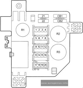
Dodge RAM 1500 Classic (2019 – 2023) – fuse box diagram

Dodge RAM 1500 Classic (2019 – 2023) – fuse box diagram

Year of production: 2019, 2020, 2021, 2022, 2023

Power Distribution Center

Fuse Box Location

he Power Distribution Center is located in the engine compartment near the battery. This center contains cartridge fuses, micro fuses, relays, and circuit breakers.

Dodge RAM 1500 (2019 - 2023) - fuse box location - engine compartment
Dodge RAM 1500 (2019 – 2023) – fuse box location – engine compartment

Fuse Box Diagram

Dodge RAM 1500 (2019 - 2023) - fuse box diagram - engine compartment
Dodge RAM 1500 (2019 – 2023) – fuse box diagram – engine compartment
Cartridge Fuse Micro Fuse Description
F01 80A Black Rad Fan Control Module – If Equipped
F02 Spare
F03 60A Yellow Rad Fan HI / LO
F04 Spare
F05 40A Green 2019-2021: Compressor For Air Suspension – If Equipped
2022-2023: Spare
F06 50A Red ABS Pump Mtr
F07 40A Green Starter Solenoid
F08 20A Blue NOx Sensor
F09 40A Green 30A Yellow 2019: Aux Relay Output / Diesel Fuel Heater – If Equipped
2020: Diesel Fuel Heater – If Equipped (Special Services Vehicle & Cummins Diesel)
2021: Diesel Fuel Heater
2023: Brake Vac Pump
F10 40A Green / 50A Red 2020-2023: Body Controller / Exterior Lighting #2
F11 30A Pink Integrated Trailer Brake Module – If Equipped
F12 40A Green Body Controller #3 / Power Locks
F13 40A Green Blower Motor
F14 40A Green Body Controller #4 / Exterior Lighting
F15 40A Green Spare / Special Services Only
F16 30A Pink Smart Bar – If Equipped
F17 Spare
F18 Spare
F19 20A Blue (1500 LD Diesel)
30A Pink (Cummins Diesel)
2019-2021: SCR – If Equipped
2022-2023: Spare
F20 30A Pink Passenger Door Module
F21 30A Pink Drive Train Control Module
F22 20A Blue / 30A Pink / 25A White Engine Control Module
PCM – If Equipped (Cummins Diesel)
F23 30A Pink Body Controller #1 / Interior Lighting
F24 30A Pink Driver Door Module
F25 30A Pink Front Wiper
F26 30A Pink Antilock Brakes / Stability Control Module / Valves – If Equipped
F27 Spare
F28 20A Blue Trailer Tow Backup Lights – If Equipped
F29 20A Blue Trailer Tow Parking Lights – If Equipped
F30 30A Pink 2019: Trailer Tow Receptacle / Trailer Tow (Separate E-Brake) / Trailer Tow (BUX)
2020-2023: Trailer Tow Receptacle
F31 30A Pink 2019: Diesel Heater Control – If Equipped (DS 1500 LD Diesel)
2020-2021: Urea Heater Control – If Equipped (1500 LD Diesel)
2022-2023: Spare
F32 2019: Aux Feed, Special Services Vehicle – If Equipped (DS 1500 Only)
2020-2023: Spare
F33 20A Blue 2019: Trans Control Module – If Equipped (HD Only) Aux Feed, SSV Only (DS 1500 Only)
2020: Special Services Vehicle Only
2021-2023: Transmission Control Module
F34 30A Pink 2019: Vehicle System Interface Module #2 – If Equipped (HD Only), SSV (DS 1500 Only)
2020-2023: Vehicle System Interface Module #2 – If Equipped
F35 30A Pink Sunroof – If Equipped
F36 30A Pink Electric Back Light – If Equipped
F37 30A Pink Diesel Fuel Heater #2
F38 30A Pink Power Inverter 115 Volt AC – If Equipped
F39 20A Blue 2019-2020: Power Outlet – Special Services Only
2020-2023: Spare
F40 Spare
F41 10A Red 2019: Active Grille Shutter / Active Air Dam – If Equipped
2020-2023: Active Grille Shutter – If Equipped
F42 20A Yellow Horn
F43 Spare
F44 10A Red Diagnostic Port
F45 Spare
F46 10A Red Upfitter – If Equipped
F47 Spare
F48 Spare
F49 10A Red 2019: Instrument Panel Cluster / HVAC (DS 1500 Only)
2020: Instrument Panel Cluster (Except Fleet Vehicles)
2021-2022: ICS / HVAC
2023: Instrument Panel Cluster / SGW
F50 2019-2021: Air Suspension Control Module – If Equipped
2022-2023: Spare
F51 10A Red 2019: Ignition Node Module / Keyless Ignition Node Module, Radio Frequency Hub Module / Electric Steering Column Lock – If Equipped
2020: Ignition Node Module / Keyless Ignition (Instrument Panel Cluster – Fleet Vehicles Only)
2021-2022: Ignition Node Module
2023: Ignition Node Module / Keyless Ignition Node Module, Radio Frequency Hub Module
F52 5A Tan Battery Sensor
F53 20A Yellow Trailer Tow – Left Turn/Stop Lights – If Equipped
F54 20A Yellow Adjustable Pedals – If Equipped
F55 Spare
F56 15A Blue 2019-2021: Additional Diesel Content – If Equipped
2022-2023: Spare
F57 20A Yellow 2019: TCM/PCM / Solenoid Trans Pressure SW (RFE Trans Only) – If Equipped (HD Only) Transmission (DS 1500 Only)
2020-2023: Transmission
F58 20A Yellow Spare
F59 10A Red 2020-2023: SCR Relay
F60 15A Blue 2019-2021: Underhood Lamp / TCM
2022-2023: Spare
F61 10A Red 2019: UREA Sensor / PM Sensor – If Equipped (DS 1500 LD Diesel & Cummins Diesel)
2020: PM Sensor – If Equipped (1500 LD Diesel & Cummins Diesel)
2021-2023: PM/NH3 Sensor
F62 10A Red Air Conditioning Clutch
F63 20A Yellow 2019: Ignition Coils (Gas), Ignition Coils Capacitors (Gas) / Short Runner Valve Actuator / Urea Heater Control Unit (DS 1500 LD Diesel) / RLY Coil Feed-SCR (DS 1500 LD Diesel)
2020: Ignition Coils (Gas), Urea Heater (Cummins Diesel)
2021-2023: Ignition Coils
F64 25A Clear 2019: Fuel Injectors / Powertrain Control Module / SRV – If Equipped
2020-2022: Fuel Injectors / Powertrain
2023: Fuel Injectors / PCM / ECM / SRV
F65 Spare
F66 10A Red 2019: Sunroof / Light and Rain Sensor Module / Inside Rearview Mirror / Passenger Window SW / USB Port Rear / Feed for R/A RLY #2 Coil – If Equipped
2020: Sunroof / Passenger Window Switches / Rain Sensor
2021-2023: Sunroof / LRSM
F67 10A Red Bluetooth / CDM
F68 10A Red 2022-2023: AEB RACAM Heater
F69 15A Blue 2020-2021: Mod SCR 12 Volt (Cummins Diesel) – If Equipped
2022-2023: Spare
F70 30A Green 2019: Fuel Pump Motor / K09 RLY Coil Feed (Cummins Diesel) – If Equipped
2020-2023: Fuel Pump Motor
F71 25A Clear Amplifier
F72 10A Red 2019: PCM / DC/DC Converter Voltage- If Equipped (DS 1500 Only)
2020-2021: PCM – If Equipped
2022-2023: Spare
F73 20A Yellow Fuel Transfer Pump
F74 20A Yellow 2020: Brake Vacuum Pump Gas/Diesel – If Equipped (Gas Engine & 1500 LD Diesel)
2021-2022: Vacuum Pump
2023: Spare
F75 10A Red 2019-2020: Coolant Temperature Valve Actuator
2021-2023: Cool Temp / SCR Relay
F76 10A Red Brake System Module (Antilock Brakes & Electronic Stability Control) / Stop Lamp Switch / Electric Park Brake / Clutch Pedal Switch
F77 10A Red 2019: Drivetrain Control Module / ELSD / Front Axle Disconnect Module / Transmission Control Relay / RDM / Power Take Off Unit – If Equipped (DS 1500 Only)
2020: Drivetrain Control Module / Front Axle Disconnect Module
2021-2022: DTCM / ELSD / PTU / RDM
2023: DTCM / ELSD / FAD / PTU / RDM / EGS53 TRNS RLY CNTRL
F78 10A Red Engine Control Module / Powertrain Control Module / Electric Power Steering
F79 15A Blue 2019-2021: ID / Clearance Lights
2022-2023: Spare
F80 10A Red Universal Garage Door Opener / Compass / Anti-Intrusion Module
F81 20A Yellow Trailer Tow Right Turn / Stop Lights – If Equipped
F82 10A Red Steering Column Control Module / Cruise Control
F83 Spare
F84 15A Blue 2019: ASBM / HVAC / ICS / Rear Heated Seat Switches
2020: Switch Bank / Instrument Cluster
2021-2022: ICS
2023: ASBM / HVAC / ICS
F85 10A Red Airbag Module (ORC)
F86 10A Red Airbag Module (ORC)
F87 10A Red 2019: Air Suspension / Trailer Tow / DC/DC Converter (Voltage Stabilizer) / Steering Column Control Module / Occupant Classification Sensor (DS 1500 Only)
2020-2023: Air Suspension Module / Trailer Tow / Steering Column Control Module
F88 15A Blue Instrument Panel Cluster
F89 Spare
F90 / F91 20A Yellow Power Outlet RR – BATT / Power Outlet RR – ACC (Customer Selectable)
F92 Spare
F93 20A Yellow Cigar Lighter
F94 10A Red Shifter / Transfer Case Module
F95 10A Red 2019: Rear Camera / Park Assist / Blind Spot Sensor / Compass
2020-2023: Rear Camera / Park Assist – If Equipped
F96 10A Red 2019: Rear Seat Heater Switch / Trunk Lamp With Flashlamp Charger / Truck Lamp – If Equipped
2020-2023: Rear Seat Heater Switch
F97 25A Clear Rear Heated Seats And Heated Steering Wheel
F98 25A Clear Front Heated Seats
F99 10A Red HVAC / DASM
F100 10A Red Upfitters
F101 15A Blue 2019: SSV Only
2020: Electrochromatic Mirror / Smart High Beams – If Equipped
2021-2023: Spare
F102 Spare
F103 Spare
F104 20A Yellow Power Outlets (Instrument Panel / Center Console)

WARNING: Terminal and harness assignments for individual connectors will vary depending on vehicle equipment level, model, and market.

Holden Rodeo (RA; 2007 – 2008) – fuse box diagram

Holden Rodeo (RA; 2007 – 2008) – fuse box diagram

Year of production: 2007, 2008

Passenger Compartment Fuse Box

Fuse Box Location

The fuses are located behind a cover on the driver’s side of the dash panel.
To open the fuse cover in the dash panel, open the driver’s side door, pull the top of the cover out, then pivot downwards.

Holden Rodeo (RA; 2007 - 2008) - fuse box location - passenger compartment
Holden Rodeo (RA; 2007 – 2008) – fuse box location – passenger compartment

Fuse Box Diagram

Holden Rodeo (RA; 2007 - 2008) - fuse box diagram - passenger compartment
Holden Rodeo (RA; 2007 – 2008) – fuse box diagram – passenger compartment
Amps Function
1
2 10A HFV6: Meter
3
4 10A/15A Petrol L4: IG coil
HFV6: Engine
Diesel: TCM
5 15A Back light
6 10A Turn light
7 10A Elec. IG
8 10A Petrol L4, Diesel: Engine
HFV6: ECU
9 10A ABS / 4WD
10 20A Frt wiper
11 10A Audio
12 20A Cigar & Acc socket
13 15A Audio (+B)
14 20A Door Lock
15 10A Meter (+B)
16 10A Room light
17
18 15A Stop light
19
20 10A Starter
21 10A SRS
SBF10 20A RR Def (Slow blow fuse)
SBF11 30A Power Window (Slow blow fuse)
B-7 Rear defogger relay
B-8 Power window relay
B-40

Engine Compartment Fuse Box

Fuse Box Location

This fuse box is located on the passenger side of the engine compartment near the battery.
To remove the cover, press the catch on the side of the fuse box towards the engine and release the two tabs at the opposite side.

Holden Rodeo (RA; 2007 - 2008) - fuse box location - engine compartment
Holden Rodeo (RA; 2007 – 2008) – fuse box location – engine compartment

Fuse Box Diagram

Holden Rodeo (RA; 2007 - 2008) - fuse box diagram - engine compartment
Holden Rodeo (RA; 2007 – 2008) – fuse box diagram – engine compartment
Amps Function
1 10A/15A Petrol L4: ECM
HFV6: ECM
Diesel: ACG (S)
2 10A/15A HFV6: O2 Sensor pre
Diesel: TCM
3 10A/20A Petrol L4: Trailer
HFV6: ECM (B)
Diesel: Fuel pump
4 10A Petrol L4: ACG (S)
HFV6: TCM/PIM (B)
Diesel: Engine
5 10A H/light-high (Right)
6 10A H/light-high (Left)
7 10A H/light-low (Right)
8 10A H/light-low (Left)
9 20A Petrol L4: Fuel pump
HFV6, Diesel: Trailer
10 10A/20A Petrol L4: O2 Sensor
Diesel: Cond. Fan
11 10A Tail light (Right)
12 10A Illumi & tail light (Left)
13 10A A/C
14 10A 4WD
15 10A Horn
16 10A Hazard
17 15A HFV6: O2 Sensor post
18 15A HFV6: IGN. coil (RH)
19 15A HFV6: IGN. coil (LH)
20 100A/120A Petrol L4, Diesel: Main Fuse
21 20A/40A HFV6: Frt fog light
Diesel: ABS-1
22 20A/60A HFV6: Rad. fan
Diesel: ABS-2
23 20A/40A Petrol L4: Cond. Fan
HFV6: Fuel pump
Diesel: ECM
24 40A IG-1
25 30A HFV6, Diesel: Blower
26 20A/40A Petrol L4: Frt fog light
HFV6: ABS-1
Diesel: Frt fog light
27 20A/30A/60A Petrol L4: Blower
HFV6: ABS-2
Diesel: Glow
28 50A/60A IG-2
Relays:
X-1 Petrol L4: Tail light
HFV6, Diesel: Fog light
X-2 Petrol L4: Fuel pump
HFV6, Diesel: Tail light
X-3 Horn
X-4 H/light dimmer
X-5 Diesel: Glow
X-6 Petrol L4: Starter
HFV6, Diesel: Headlight
X-7 Petrol L4: Headlight
Diesel: Starter cut
X-8 Diesel: Starter
X-9 Petrol L4: Frt fog light
Diesel: Cond. Fan
X-10 Petrol L4: Cond. fan
Diesel: Transmission
X-11 Heater
X-12 HFV6, Diesel: ECM main
X-13 Petrol L4: Starter cut
HFV6, Diesel: Fuel pump
X-14 A/C comp.
X-15 Petrol L4, Diesel: A/C thermo
HFV6: Starter


WARNING: Terminal and harness assignments for individual connectors will vary depending on vehicle equipment level, model, and market.
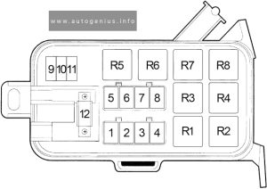
Holden Rodeo (RA; 2003 – 2006) – fuse box diagram

Holden Rodeo (RA; 2003 – 2006) – fuse box diagram

Year of production: 2003, 2004, 2005, 2006

Passenger Compartment Fuse Box

Fuse Box Location

The fuses are located behind a cover on the driver’s side of the dash panel.
To open the fuse cover in the dash panel, open the driver’s side door, pull the top of the cover out, then pivot downwards.

Holden Rodeo (Ra; 2003 - 2006) - fuse box location - passenger compartment
Holden Rodeo (Ra; 2003 – 2006) – fuse box location – passenger compartment

Fuse Box Diagram

Holden Rodeo (Ra; 2003 - 2006) - fuse box diagram - passenger compartment
Holden Rodeo (Ra; 2003 – 2006) – fuse box diagram – passenger compartment
Amps Function
1
2 10A ABS
3
4 15A Back Up
5 15A Meter
6 10A Turn
7 15A Elec. IG
8 15A Engine
9 20A Frt Wiper/Washer
10 15A Egr
11 10A Audio
12 15A/20A Cigar/Acc Socket
13 15A Audio (+B)
14 20A Door Lock
15 10A Meter (+B)
16 10A Dome Light
17 10A Anti Theft
18 15A Stop
19 15A Acc Socket (according to 2003)
20 10A Starter
21 10A SRS
SBF10 20A RR Def (Slow blow fuse)
SBF11 30A Power Window (Slow blow fuse)
B-7 Rear defogger relay
B-8 Power window relay
B-40 Acc Socket relay (according to 2003)

Engine Compartment Fuse Box

Fuse Box Location

This fuse box is located on the passenger side of the engine compartment near the battery.
To remove the cover, press the catch on the side of the fuse box towards the engine and release the two tabs at the opposite side.

Holden Rodeo (Ra; 2003 - 2006) - fuse box location - engine compartment
Holden Rodeo (Ra; 2003 – 2006) – fuse box location – engine compartment

Fuse Box Diagram

Holden Rodeo (Ra; 2003 - 2006) - fuse box diagram - engine compartment
Holden Rodeo (Ra; 2003 – 2006) – fuse box diagram – engine compartment
Amps Function
1 10A/15A/20A ECM
2 10A/15A 6VE1: ECM
HFV6: O2 pre heat
4JH1-TC: RR Fog
3 10A/15A C24SE: Frt Fog
6VE1, HFV6: ECM (B)
4JH1-TC: Frt Fog
4 10A/15A C24NE, C24SE: ACG (S)
6VE1: Frt Fog
HFV6: TCM/PIM (B)
4JH1-TC: ACG (S) (according to 2003)
5 10A Illumination (according to 2003)
C24SE: Illumination (according to 2006)
HFV6, 4JH1-TC: Illumination & Tail (right) (according to 2006)
6 10A Tail light (according to 2003)
C24SE: Illumination (according to 2006)
HFV6, 4JH1-TC: Illumination & Tail (left) (according to 2006)
7 10A H/Light (right)
8 10A H/Light (left)
9 10A/20A C24NE, C24SE: Fuel Pump
HFV6, 4JH1-TC: Trailer (according to 2006)
6VE1: O2 Sensor (according to 2003)
10 10A/20A C24NE, C24SE: O2 Sensor
6VE1: Fuel Pump
HFV6: O2 Heat Post
4JH1-TC: ACG (S)
11 15A HFV6: Coil-RH
12 15A HFV6: Coil-LH
13 10A A/C
14 10A 4WD
15 10A Horn
16 10A/15A Hazard
17 80A/100A Main fuse
18 20A HFV6: Frt Fog
4JH1-TC: Cond, Fan
19 50A/60A HFV6: Rad, Fan
4JH1-TC: Glow
20 20A/30A C24NE, C24SE, 6VE1: Cond, Fan
HFV6: Fuel Pump
4JH1-TC: ECM
21 40A IG 1
22 40A 6VE1, 4JH1-TC: ABS-1 (according to 2003)
HFV6, 4JH1-TC: IG 1 (according to 2006)
23 30A/40A 6VE1, 4JH1-TC: ABS-2
24 30A Blower
25 50A IG 2
Relays:
X-1 Tail light
X-2 Fuel pump (according to 2003)
4JH1-TC (according to 2006): Frt Fog
X-3 Horn
X-4 Dimmer
X-5 6VE1: Fog light (according to 2003)
4JH1-TC: Glow
X-6 C24NE, 6VE1: Starter (according to 2003)
C24SE: Starter
4JH1-TC: Starter cut
X-7 Cond, Fan (according to 2003)
C24SE, 4JH1-TC (according to 2006): H/Light
X-8 4JH1-TC: Starter (according to 2006)
X-9 6VE1: Hazard (right) (according to 2003)
C24SE: FRT Fog light (according to 2006)
4JH1-TC: Cond fan (according to 2006)
X-10 6VE1: Hazard (left) (according to 2003)
C24SE: Cond fan (according to 2006)
HFV6: FRT Fog light (according to 2006)
X-11 Heater
X-12 Headlights (according to 2003)
HFV6: ECM Main (according to 2006)
X-13 6VE1: ECM Main (according to 2003)
C24SE: Starter cut (according to 2006)
HFV6: Starter (according to 2006)
4JH1-TC: ECM Main (according to 2006)
X-14 A/C compressor
X-15 Thermo (according to 2003)
C24SE, 4JH1-TC: Thermo (according to 2006)
HFV6: H/light (according to 2006)


WARNING: Terminal and harness assignments for individual connectors will vary depending on vehicle equipment level, model, and market.
Holden Equinox (EQ; 2017 – 2020) – fuse and relay box diagram

Holden Equinox (EQ; 2017 – 2020) – fuse and relay box diagram

Year of production: 2017, 2018, 2019, 2020


The Holden Equinox (EQ), a compact crossover, was manufactured between 2017 and 2020. In this article, you’ll find fuse box diagrams for the 2017, 2018, 2019, and 2020 models, along with details on the location of the fuse panels within the vehicle and the specific assignment of each fuse and relay (fuse layout).


Passenger Compartment Fuse Box

Fuse Box Location

The instrument panel fuse panel is located under the instrument panel on the driver side. To access the fuses, press the tab on each end of the fuse box and remove the cover.

Holden Equinox (EQ; 2017 - 2020)- fuse box location - passenger compartment
Holden Equinox (EQ; 2017 – 2020)- fuse and relay box location – passenger compartment


Fuse Box Diagram

Holden Equinox (EQ; 2017 - 2020)- fuse box diagram - passenger compartment
Holden Equinox (EQ; 2017 – 2020)- fuse and relay box diagram – passenger compartment


Assignment of the fuses in the passenger compartment

Usage
F01 DC AC inverter
F02 Front windows
F03 Trailer brake
F04 Heating, ventilation, and air conditioning blower
F05 Body control module 2
F06 Cyber security
F07
F08 Body control module 3
F09 Amplifier
F10
F11
F12
F13
F14 Electronic shifter
F15 Transmission control module
F16 Front heated seats 1
F17 Left data link connector
F18 Body control module 7
F19 Exterior mirror fold
F20 Body control module 1
F21 Body control module 4
F22 Body control module 6
F23 Electric steering column lock
F24 Sensing and diagnostic module
F25 Occupancy sensor
F26
F27 Power seats
F28 Rear windows
F29
F30 Front heated seats switch
F31 Steering wheel controls
F32 Body control module 8
F33 Heating, ventilation, and air conditioning
F34 Passive entry, passive start
F35 Liftgate latch
F36 Shift charger
F37 Cigarette lighter
F38 OnStar
F39 Instrument panel USB
F40 Camera module/ Liftgate module
F41 Parking assist module
F42 Radio
Circuit Breakers
CB1 Front auxiliary power outlet
CB2 Auxiliary power outlet console
Relays
K01 Deadbolt
K02 Retained accessory power
K03 Liftgate
K04
K05 Logistics

Engine Compartment Fuse Box

Fuse Box Location

To remove the fuse panel cover, squeeze the clips on the cover and lift it straight up.

Holden Equinox (EQ; 2017 - 2020)- fuse box location - engine compartment
Holden Equinox (EQ; 2017 – 2020)- fuse and relay box location – engine compartment


Fuse Box Diagram

Holden Equinox (EQ; 2017 - 2020)- fuse box diagram - engine compartment
Holden Equinox (EQ; 2017 – 2020)- fuse and relay box diagram – engine compartment


Assignment of the fuses in the engine compartment

Usage
F01 Front/Rear washer pump
F02 Air Conditioning Clutch
F03 Starter Solenoid 1
F04 Automatic Headlamp Levelling
F05 Left High-beam Headlamp
F06 Right High-beam Headlamp
F07 2018: Vacuum Pump
F08 Horn
F09
F10
F11 Diesel fuel heate
F12 2018: Fuel injectors – even
2019-2020: Engine control module
F13 2018: Fuel injectors – odd
2019-2020: Ignition coils
F14 Lambda sensor 2
F15 Lambda sensor 1
F16
F17
F18 2018: Front wiper
F19 Front wiper speed control
F20 Engine control module
F21 Starter solenoid 2
F22 2018: Right Low-beam Headlamp
2019-2020: Right daytime running lamp
F23 2018: Left Low-beam Headlamp
2019-2020: Left daytime running lamp
F24 Engine control module
F25
F26 Transmission control module
F27 Front Fog Lamps
F28
F29 Shift Control
F30 Heated Steering Wheel
F31 Engine Control Module / Transmission Control Module
F32 Transmission Range Control Module
F33 Antilock brake valves
F34 FlexFuel Sensor
F35 Australia Trailer Tow
F36 Variable Functions
F37 Motorised headlamp
F38 NOx soot sensor (diesel only)
F39 2018: Fuel Pump
F40 LD Trailer
F41 Selective catalytic reduction module (diesel only)
F42 Interior Rear View Mirror
F43
F44 Passenger side Ventilated Seat
F45 Canister vent solenoid
F46 Driver side Ventilated Seat
F47
F48 Fuel System
F49 Steering column lock assembly
F50 DC DC converter 2
F51 Front Heated Seats
F52
F53 Rear Window Demister
F54 Afterboil pump
F55 Mirror Defroster
F56 Rear Wiper
F57 Antilock Brake Pump
Relays
K01 High-beam headlamps
K02* Horn
K03* 2018: Horn
K04* Front Washer Pump
K05* Rear Washer Pump
K06 Air Conditioning Control
K07 Headlamp Wash Pump
K08 Front Wiper speed
K09 Starter Solenoid
K10 Fuel heater (diesel only)
K11 Starter Solenoid
K12 2018: Transmission Oil Pump
K13 2019-2020: Headlamps / Daytime running lamps
K14 Headlamps / Daytime running lamps
K15 Fog lamps
K16 Engine Control Module
K17* Selective catalytic reduction (diesel only)
K18 Run/Crank
K19 Fuel pump
K20 Rear Window Demister
K21* Rear Wiper Control
K22* Front Wiper Control
K23* Coolant pump
* PCB relays are not serviceable.


Rear Compartment Fuse Box

Fuse Box Location

The rear fuse panel is behind the side trim in the rear compartment.  To access the fuse panel, carefully release the upper edge and remove the trim plate

Holden Equinox (EQ; 2017 - 2020)- fuse box location - rear compartment
Holden Equinox (EQ; 2017 – 2020)- fuse and relay box location – rear compartment


Fuse Box Diagram

Holden Equinox (EQ; 2017 - 2020)- fuse box diagram - rear compartment
Holden Equinox (EQ; 2017 – 2020)- fuse and relay  box diagram – rear compartment


Assignment of the fuses in the rear compartment

Usage
F1 Exhaust fuel heater
F2 Liftgate
F3 Trailer auxiliary power
F4 2018: Power seats
2019-2020: Passenger power seat
F5 Memory seat module
F6 Sunroof
F7 Side blind spot alert
F8 Trailer reverse lamps
F9 Rear heated seat 1
F10 2018: Parking assist
2019-2020: Park lamps
F11 Rear heated seat 2
F12
F13 Trailer park lamp
F14 Right trailer brake lamp/Turn signal lamp
F15 Left park lamp
F16 Right park lamp
F17 2019-2020: Video processing module
F18 Left trailer brake lamp/Turn signal lamp
F19 All-wheel drive
F20 Lumbar
F21 Rear auxiliary power outlet
F22 Rear drive unit
Relays
K1 Right trailer brake lamp / Turn signal lamp
K2 Trailer reverse lamps
K3 Left trailer brake lamp / Turn signal lamp
K4 Park lamps
K5 Selective catalytic reduction (SCR) (diesel only)

WARNING: Terminal and harness assignments for individual connectors will vary depending on vehicle equipment level, model, and market.
Holden Colorado (RG; 2017 – 2020) – fuse box diagram

Holden Colorado (RG; 2017 – 2020) – fuse box diagram

Year of production: 2017, 2018, 2019, 2020


This article provides the second-generation Holden Colorado (RG, facelifted) produced from 2017 to 2020. It includes fuse box diagrams for the 2017, 2018, 2019, and 2020 models, provides details on the location of the fuse panels within the vehicle, and explains the function of each fuse (fuse layout).


Passenger Compartment Fuse Box

Fuse Box Location

The fuse box is in a storage compartment on the driver’s side of the instrument panel. Remove the instrument panel cap in the direction of the arrow to access.

Holden Cascada (RG; 2013 - 2015)- fuse box location - passenger compartment
Holden Cascada (RG; 2017 – 2020)- fuse box location – passenger compartment


Fuse Box Diagram

Holden Cascada (RG; 2017 - 2020)- fuse box diagram - passenger compartment
Holden Cascada (RG; 2017 – 2020)- fuse box diagram – passenger compartment


Assignment of the fuses in the passenger compartment (instrument panel)

Amps Usage
1 20A Body Control Module (6)
3 20A Cigarette Lighter (if available)
6 20A Front and Rear Power Outlets (if available)
7 30A Body Control Module (8)
10 20A Radio (if available)
11 2A Ignition Switch
12 15A Side Blind Zone (SBZ) (If available)
13 15A Body Control Module (3)
14 10A Front A/C Control Module
15 15A Seat Heated (If available)
16 15A Body Control Module (1)
17 30A Front Door Power Window Switch
19 30A Rear Door Power Window Switch (if available)
20 15A Body Control Module (4)
21 10A Spare
22 30A Power Seat (if available)
25 10A Sensing and Diagnose Module (SDM)
26 15A Body Control Module (2)
27 2A Clock Spring
28 7.5A Data Link Connector (DLC)
31 10A Instrument Panel Cluster (IPC), Displays – Radio (Instrument Panel), USB
33 10A Central Gateway Module (CGM) – Cyber Security
34 30A Front A/C Blower
37 10A Front Collision Alert (FCA) / Rain Sensor (if available)
39 10A Rear View Mirrors (if available)
53 40A BUS-C (fuses: F12, F33, F37, F39, F40)
54 40A Accessory (12V)
Relays
RLY45 C-Enable
RLY46 RAP and Accessory (12V)
RLY48 Run relay


Engine Compartment Fuse Box

Fuse Box Location

The fuse box is in the front left of the engine compartment. Disengage the cover, lift it upward and remove it.

Holden Cascada (RG; 2013 - 2015)- fuse box location - engine compartment
Holden Cascada (RG; 2017 – 2020)- fuse box location – engine compartment


Fuse Box Diagram

Holden Cascada (RG; 2013 - 2015)- fuse box diagram - engine compartment
Holden Cascada (RG; 2017 – 2020)- fuse box diagram – engine compartment


Assignment of the fuses in the engine compartment

Amps Usage
1 10A Compressor A/C Clutch
2 Not Used
3 15A Electric Power Steering (EPS) (if available)
4 Not Used
5 15A Horn
6 15A Front Fog Lamp (if available)
7 10A High Beam LH
8 10A High Beam RH
9 7.5A Engine Control Module – (Diesel)
10 15A Powertrain Relay (3) – (Diesel)
11 20A Engine Control Module (1) (Diesel)
12 10A Powertrain Relay (1)
13 10A Powertrain Relay (2)
14 15A Powertrain Relay (4)
15 15A Run Crank Relay Signal
16 15A Automatic Transmission Control Module (if available)
17 10A Transfer Case Module, Head Lamp Leveling, Trailer Interface Module (if available)
18 10A Power Supply Cluster – A/C – Airbag Module
19 20A Fuel Pump (Diesel)
20 Not Used
21 30A Rear Defogger (if available)
22 15A Outside Rear View Mirror Defogger (if available)
23 15A 2017: Cab Heater (Diesel)
24 20A Rear Wiper (SUV)
25 10A Front / Rear (SUV) Washer Pump
26 10A Park Assist (if available)
27 5A Body Control Module
28 15A Auxiliary Lamps Provision (If equipped)
29 30A ABS or ESC Module (if available)
30 10A Horn
31 15A Body Control Module
32 15A Engine Control Module (Battery) (Diesel)
33 10A Communication Wire Between Modules
SB01 50A ABS or ESC Module Pump (if available)
SB02 30A Transfer Case Control Module (4X4) (if available)
SB03 60A Preheating Glow Plug Module (Diesel)
SB04 Not Used
SB05 30A Starter Motor Solenoid
SB06 30A Front Wiper
SB07 30A Fuel Heater (Diesel)
SB08 Not Used (Diesel)
SB09 30A Spare
F34* 30A Trailer Hitch Module (if available)
* Located near battery positive terminal
Relays
RLY01 Starter
RLY03 High Beam
RLY05 2017: Viscous Heater (Diesel)
RLY08 Front Wiper Control
RLY09 Front Wiper Speed
RLY10 Rear Defogger and Outside Rear View Mirror Defogger (if available)
RLY11 Powertrain
RLY12 A/C Clutch
RLY13 Fuel Heater (Diesel)
RLY14 Not Used (Diesel)
RLY15 Not Used
RLY18 Run Crank
RLY19 Fuel Pump (Diesel)

WARNING: Terminal and harness assignments for individual connectors will vary depending on vehicle equipment level, model, and market.
Holden Colorado (RG; 2013 – 2016) – fuse and relay box diagram

Holden Colorado (RG; 2013 – 2016) – fuse and relay box diagram


Year of production: 2013, 2014, 2015, 2016


This article provides the second-generation Holden Colorado (RG, pre-facelift), manufactured from 2012 to 2016. It includes fuse box diagrams for the 2013, 2014, 2015, and 2016 models, along with details on the location of the fuse panels inside the vehicle and the specific functions of each fuse (fuse layout).


Passenger Compartment Fuse Box

Fuse Box Location

The fuse box is in a storage compartment on the driver’s side of the instrument panel.

Holden Cascada (RG; 2013 - 2015)- fuse box location - passenger compartment
Holden Cascada (RG; 2013 – 2015)- fuse and relay box location – passenger compartment


  1. Press the sides of the storage compartment inwards.
  2. Lift the storage compartment until it audibly disengages.
  3. Remove by pulling rearwards.
  4. Reinstall in the reverse order.


Fuse Box Diagram

Holden Cascada (RG; 2013 - 2015)- fuse box diagram - passenger compartment
Holden Cascada (RG; 2013 – 2015)- fuse and relay box diagram – passenger compartment


Assignment of the fuses in the passenger compartment (instrument panel)

Amps Description
1 15A HVAC AUTO
2 15A BODY CONTROL MODULE (6)
3 15A BODY CONTROL MODULE (5)
4 20A CIGAR LIGHTER AND POWER OUTLET
5 2A CLOCK SPRING
6 30A POWER WINDOW
7 20A POWER OUTLET
8 15A BODY CONTROL MODULE (2)
9 15A BODY CONTROL MODULE (4)
10 30A BODY CONTROL MODULE (8)
11 40A RAP & ACCESSORY 12V
12
13
14 7.5A DATA LINK CONNECTOR (DLC)
15 10A SENSING AND DIAGNOSTIC MODULE (SDM)
16 10A INSTRUMENT PANEL CLUSTER (IPC)
17 20A RADIO
18 30A HVAC BLOWER
19 5A OUTSIDE REAR VIEW MIRRORS
20
21 10A HVAC CONTROL HEAD
22 2A IGNITION SWITCH
23 15A BODY CONTROL MODULE (5)
24 15A BODY CONTROL MODULE (3)
25 20A POWER WINDOW SWITCH
26 25A POWER SEAT


Engine Compartment Fuse Box

Fuse Box Location

The fuse box is located on the passenger’s side of the engine compartment. To disengage the cover, lift upwards and remove.

Holden Cascada (RG; 2013 - 2015)- fuse box location - engine compartment
Holden Cascada (RG; 2013 – 2015)- fuse and relay box location – engine compartment


Fuse Box Diagram

Holden Cascada (RG; 2013 - 2015)- fuse box diagram - engine compartment
Holden Cascada (RG; 2013 – 2015)- fuse and relay box diagram – engine compartment


Assignment of the fuses in the engine compartment

Amps Description
1 10A COMPRESSOR A/C CLUTCH
2 15A BCM BATT 6
3 15A SPARE
4 10A REAR LATCH
5 15A HORN
6 15A FRONT FOG LAMP
7 10A HIGH BEAM LH
8 10A HIGH BEAM RH
9 10A 2016: ENGINE CONTROL MODULE
10 15A ENGINE 3
11 20A ENGINE CONTROL MODULE1
12 10A ENGINE 1
13 10A ENGINE 2
14 15A ENGINE 4
15 15A PWT
16 15A TCM
17 10A TRANSFER CASE MODULE AND LAMP LEVELLING
18 10A CLUSTER – A/C – SDM
19 20A FUEL PUMP
20 5A SPARE
21 30A REAR WINDOW HEATER
22 15A OUTSIDE REAR VIEW MIRROR
23 15A VISCOUS HEATER
24 20A REAR WIPER
25 10A FRT WASHER
26 10A REAR PARK ASSIST
27 5A BODY CONTROL MODULE RVC
28 7.5A DRL / COLD START
29 30A ABS MODULE ESC1
30 10A 2013-2014: CONTENT THEFT RELAY
2015-2016: HORN
31 15A BODY CONTROL MODULE BATT 7
32 15A ENGINE CONTROL MODULE
33 10A COMMON ENABLE
SB01 50A ABS MODULE PUMP
SB02 30A TRANSFER CASE CONTROL MODULE (4X4)
SB03 60A GLOW PLUG MODULE (DIESEL)
SB04 20A SPARE
SB05 30A STARTER MOTOR SOLENOID
SB06 30A FRONT WIPER
SB07 30A COOL FAN
SB08
SB09 30A SPARE

WARNING: Terminal and harness assignments for individual connectors will vary depending on vehicle equipment level, model, and market.
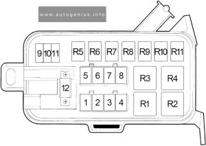
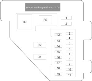
Holden Colorado (RC; 2009 – 2012) – fuse and relay box diagram

Holden Colorado (RC; 2009 – 2012) – fuse and relay box diagram


Year of production: 2009, 2010, 2011, 2012


This article provides the first-generation Holden Colorado (RC), manufactured between 2008 and 2012. It provides fuse box diagrams for the 2009, 2010, 2011, and 2012 models, along with details on the location of the fuse panels inside the vehicle. Additionally, it explains the function of each fuse (fuse layout) and relay.


Passenger Compartment Fuse Box

Fuse Box Location

The fuse panel is located on the right-hand side of the dashboard.  To open the fuse cover, open the driver’s door, pull the top of the cover out, then pivot downward.

Holden Colorado (RC; 2009 - 2012)- fuse box location - passenger compartment
Holden Colorado (RC; 2009 – 2012)- fuse and relay box location – passenger compartment


Fuse Box Diagram

Holden Colorado (RC; 2009 - 2012)- fuse and relay box diagram - passenger compartment
Holden Colorado (RC; 2009 – 2012)- fuse and relay box diagram – passenger compartment


Assignment of the fuses in the passenger compartment

Amps Description
1 10A Meter
2
3 10A/15A Petrol L4: IG coil
HFV6: Engine
Diesel: TCM
4 15A Back light
5 10A Turn light
6 10A Elec. IG
7 10A Petrol L4: Engine
HFV6: ECU
Diesel: Engine
8 10A ABS / 4WD
9 20A Frt wiper
10 10A SRS
11 10A Audio
12 20A Cigar & Acc socket
13 15A Audio (+B)
14 20A Door lock
15 10A Meter (+B)
16 10A Room light
17
18 15A Stop light
19
20 10A Starter
21 10A Spare
22 15A Spare
23 20A Spare
24 20A HFV6, Diesel: RR defog (Slow blow fuse)
25 30A HFV6, Diesel: Power window (Slow blow fuse)
26 HFV6, Diesel: RR defog relay
27 HFV6, Diesel: Power window relay
28


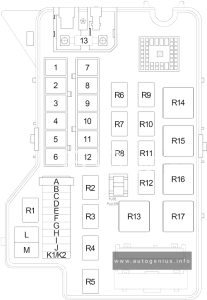
Engine Compartment Fuse Box

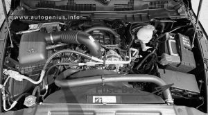
Fuse Box Location

This fuse box is located on the passenger side of the engine compartment. It contains circuit fuses, main fuses and relays.  To remove the cover, press the catch on the side of the fuse box toward the engine and release the two tabs at the opposite side.

Holden Colorado (RC; 2009 - 2012)- fuse box location - engine compartment
Holden Colorado (RC; 2009 – 2012)- fuse box location – engine compartment


Fuse Box Diagram

Holden Colorado (RC; 2009 - 2012)- fuse and relay box diagram - engine compartment
Holden Colorado (RC; 2009 – 2012)- fuse and relay box diagram – engine compartment


Assignment of the fuses in the engine compartment

Amps Description
1 10A/15A Petrol L4: ECM (15A)
HFV6: ECM (15A)
Diesel: ACG (S) (10A)
2 10A/15A HFV6: O2 Sensor pre (15A)
Diesel: ECM (B) (10A)
3 10A/20A Petrol L4: Trailer (20A)
HFV6: ECM (B) (10A)
Diesel: Fuel pump (10A)
4 10A Petrol L4: ACG (S)
HFV6: TCM/PIM (B)
Diesel: Engine
5 10A H/light-high (RH)
6 10A H/light-high (LH)
7 10A H/light-low (RH)
8 10A H/light-low (LH)
9 20A Petrol L4: Fuel pump
HFV6: Trailer
Diesel: Trailer
10 10A/20A Petrol L4: O2 Sensor (10A)
Diesel: Cond. Fan (20A)
11 10A Tail light (RH)
12 10A Illumi & tail light (LH)
13 10A A/C
14 10A HFV6: 4WD
Diesel: 4WD
15 10A Horn
16 10A Hazard
17 15A HFV6: O2 Sensor post
18 15A HFV6: IGN. coil (RH)
19 15A HFV6: IGN. coil (LH)
Slow blow fuses
20 100A/120A Petrol L4: Main (100A)
Diesel: Main (120A)
21 20A/40A HFV6: Frt fog light (20A)
Diesel: ABS-1 (40A)
22 20A/60A HFV6: Rad. Fan (60A)
Diesel: ABS-2 (20A)
23 20A/40A Petrol L4: Cond. Fan (20A)
HFV6: Fuel pump (20A)
Diesel: ECM (40A)
24 40A IG-1
25 30A HFV6: Blower
Diesel: Blower
26 20A/40A Petrol L4: Frt fog light (20A)
HFV6: ABS-1 (40A)
Diesel: Frt fog light (20A)
27 20A/30A/60A Petrol L4: Blower (30A)
HFV6: ABS-2 (20A)
Diesel: Glow (60A)
28 50A/60A Petrol L4: IG-2 (50A)
HFV6: IG-2 (60A)
Diesel: IG-2 (60A)
Relays:
X-1 Petrol L4: Tail light
HFV6: Fog light
Diesel: Fog light
X-2 Petrol L4: Fuel pump
HFV6: Tail light
Diesel: Tail light
X-3 Horn
X-4 H/light dimmer
X-5 Diesel: Glow
X-6 Petrol L4: Starter
HFV6: Headlight
Diesel: Headlight
X-7 Petrol L4: Headlight
Diesel: Starter cut
X-8 Diesel: Starter
X-9 Petrol L4: Frt fog light
Diesel: Cond. fan
X-10 Petrol L4: Cond. fan
Diesel: Transmission
X-11 Heater
X-12 HFV6: ECM main
Diesel: ECM main
X-13 Petrol L4: Starter cut
HFV6: Fuel pump
Diesel: Fuel pump
X-14 A/C comp.
X-15 Petrol L4: A/C thermo
HFV6: Starter
Diesel: A/C thermo
46
47 Horn
48 Radiator fan
49 Fuel pump
50 Headlamp levelling / Adaptive forward lighting
51
52
53 Transmission control module / Engine control module
54 Vacuum pump / lnstrument panel cluster / Heating ventilation / Air conditioning system

WARNING: Terminal and harness assignments for individual connectors will vary depending on vehicle equipment level, model, and market.
Holden Cascada (CJ; 2015 – 2017) – fuse and relay box diagram

Holden Cascada (CJ; 2015 – 2017) – fuse and relay box diagram

Year of production: 2015, 2016, 2017

Passenger Compartment Fuse Box

Fuse Box Location

The fuse box is located behind a cover in the glovebox. Open the glovebox, then open the cover and fold it down.

Holden Cascada (CJ; 2015 - 2017)- fuse box location - passenger compartment
Holden Cascada (CJ; 2015 – 2017)- fuse and relay box location – passenger compartment

Fuse Box Diagram

Holden Cascada (CJ; 2015 - 2017)- fuse box diagram - passenger compartment
Holden Cascada (CJ; 2015 – 2017)- fuse and relay box diagram – passenger compartment


Assignment of the fuses in the passenger compartment

Circuit
1 Displays
2 Body control unit / Exterior lights
3 Body control unit / Exterior lights
4 Infotainment system
5 Infotainment system / lnstrument
6 Power outlet / Cigarette lighter
7 Power outlet
8 Body control module / Left low beam
9 Body control module / Right low beam
10 Body control module / Door locks
11 Interior fan
12 Driver power seat
13 Passenger power seat
14 Diagnostic connector
15 Airbag
16 Boot lid relay
17 Air conditioning system
18 Service diagnose
19 Body control module / Brake lights / Tail lights / lnterior lights
20
21 Instrument panel
22 Ignition system
23 Body control module
24 Body control module
25
26 Trunk power outlet accessory


Engine Compartment Fuse Box

Fuse Box Location

Disengage the cover and fold it upwards until it stops. Remove the cover vertically upwards.

Holden Cascada (CJ; 2015 - 2017)- fuse box location - engine compartment
Holden Cascada (CJ; 2015 – 2017)- fuse and relay box location – engine compartment

Fuse Box Diagram

Holden Cascada (CJ; 2015 - 2017)- fuse box diagram - engine compartment
Holden Cascada (CJ; 2015 – 2017)- fuse and relay box diagram – engine compartment


Assignment of the fuses in the engine compartment

Circuit
1 Engine control module
2 Lambda sensor
3 Fuel injection / lgnition system
4 Fuel injection / lgnition system
5
6 Mirror heating
7 Fan control
8 Lambda sensor / Engine cooling
9 Rear window sensor
10 Vehicle battery sensor
11 Trunk release
12 Adaptive forward lighting / Automatic light control
13 ABS Valves
14
15 Engine control module
16 Starter
17 Transmission control module
18 Heated rear window
19 Front power windows
20 Rear power windows
21 Rear eletrical centre
22 Left high beam (Halogen)
23 Headlamp washer system
24 Right low beam (Xenon)
25 Left low beam (Xenon)
26 Front fog lights
27
28 Start stop system
29 Electric parking brake
30 ABS pump
31
32 Airbag
33 Adaptive forward lighting / Automatic light control
34 Exhaust gas recirculation
35 Power windows / Rain sensor / Exterior mirror
36 Climate control
37
38 Vacuum pump
39 Fuel system control module
40 Windscreen washer system
41 Right high beam (Halogen)
42 Radiator fan
43 Windscreen wiper
44
45 Radiator fan
46
47 Horn
48 Radiator fan
49 Fuel pump
50 Headlamp levelling / Adaptive forward lighting
51
52
53 Transmission control module / Engine control module
54 Vacuum pump / lnstrument panel cluster / Heating ventilation / Air conditioning system

Load Compartment Fuse Box

Fuse Box Location

The fuse box is on the left side of the load compartment behind a cover.

Holden Cascada (CJ; 2015 - 2017)- fuse box location - load compartment
Holden Cascada (CJ; 2015 – 2017)- fuse and relay box location – load compartment


Fuse Box Diagram

Holden Cascada (CJ; 2015 - 2017)- fuse box diagram - load compartment
Holden Cascada (CJ; 2015 – 2017)- fuse and relay box diagram – load compartment


Assignment of the fuses in the load compartment

Circuit
1 Soft top control module / Power rail right
2
3 Parking assist
4
5
6
7 Power seat
8 Soft top control module
9
10
11 Trailer module / Tyre pressure monitor and rear view camera
12 Soft top control module / Tail lights
13
14 Rear seat electrical folding
15
16 Seat ventilation / Rear view camera / Soft top control module
17
18
19 Steering wheel heating
20
21 Seat heating
22
23 Soft top control module / Power rail left
24
25
26 Jumper fuse for non logistic mode
27 Passive entry
28
29 Hydraulic unit
30
31
32 Flex Ride

WARNING: Terminal and harness assignments for individual connectors will vary depending on vehicle equipment level, model, and market.