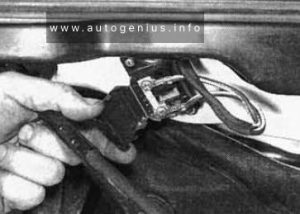
Volkswagen e-Golf (2014 – 2020) – fuse and relay box diagram

Volkswagen e-Golf (2014 – 2020) – fuse and relay box diagram


Year of production: 2014, 2015, 2016, 2017, 2018, 2019, 2020


This article provides the Volkswagen e-Golf, produced from 2014 to the 2020. It provides fuse box diagrams for the Volkswagen e-Golf models from 2014, 2015, 2016, 2017, 2018, 2019, 2029, 2021, and 2022, along with details on the location of the fuse panels within the vehicle. Additionally, it explains the fuse and relay assignments (fuse layout).


Passenger Compartment Fuse Box

Fuse Box Location
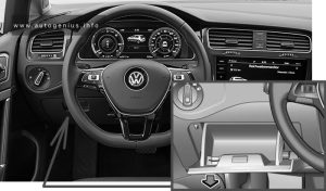
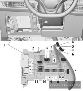
Volkswagen e-Golf (2014 - 2020) - fuse and relay box location - passenger compartment
Volkswagen e-Golf (2014 – 2020) – fuse and relay box location – passenger compartment


Fuse Box Diagram

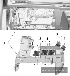
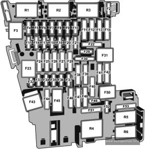
Volkswagen e-Golf (2014 - 2020) - fuse and relay box diagram - passenger compartment
Volkswagen e-Golf (2014 – 2020) – fuse and relay box diagram – passenger compartment
Assignment of the fuses in the passenger compartment (instrument panel -SC-)
Amps Function / Component
SC1
SC2
SC3
SC4 10A 2014-2017:
Vehicle electrical system control module
– Anti-theft alarm system
SC4 7.5A/10A 2018-2020:
Alarm horn
SC5 5A/7.5A Data bus on board diagnostic interface
SC6 5A 2014-2015:
Anti-theft alarm system sensor2015-2020:
Selector lever
SC7 10A 2014-2015:
Heater and A/C controls
Climatronic control module
Selector lever
Rear window defogger relay2015-2020:
Heater and A/C controls
Climatronic control module
Rear window defogger relay
SC8 7.5A/10A 2014-2015:
Rotary light switch
Electromechanical parking brake button
Rain/light recognition sensor
Diagnostic connection2015-2020:
Rotary light switch
Electromechanical parking brake button
Rain/light recognition sensor
Anti-theft alarm system sensor
Diagnostic connection
SC9 5A/7.5A Steering column electronics control module
SC10 10A Front information display control head
SC11 25A 2014-2017:
Left front seat belt tensioner control module
SC11 40A 2017-2020:
Vehicle electrical system control module
– Left front headlamp
SC12 20A Information electronics control module 1
SC13 10A 2014-2017:
High-voltage battery 1
High-voltage system maintenance connector
SC13 25A 2017-2020:
Left front seat belt tensioner control module
SC14 30A Fresh air blower control module
SC15 10A Electronic steering column lock control module
SC16 7.5A Mobile communication 2-way signal amplifier
Telephone baseplate
Voltage converter for USB charge module (2014-2015)
USB distributor
Chip card reader control module
TV tuner
SC17 5A Instrument cluster
Control module for emergency call module and communication unit
Telematics Control Module for Real-Time Monitoring (2018-2020 vehicles with China equipment)
SC18 7.5A Rearview camera
Release button in rear lid handle
SC19 7.5A Access/start system interface
SC20 5A High-voltage battery charging voltage control module
SC21
SC22
SC23 40A 2014-2017:
Vehicle electrical system control module
– Right front headlamp
SC24 40A 2017-2020:
Vehicle electrical system control module
– Right front headlamp
SC25 30A Driver Door Control Module (LHD)
Left Rear Window Regulator Motor (LHD)
Front Passenger Door Control Module (RHD)
Right Rear Window Regulator Motor (RHD)
SC26 30A Vehicle electrical system control module
– Front heated seat
SC27 30A 2014-2017:
Digital sound system control module2017-2020:
Vehicle electrical system control module
– Terminal 30
SC28
SC29
SC30 10A 2017-2020:
High-voltage battery 1
High-voltage system maintenance connector
SC31 40A 2014-2017:
Vehicle electrical system control module
– Left front headlamp
SC32 7.5A/10A Driver assistance systems front camera
Distance regulation control module
Parking Aid Control Module
Parallel Parking Assistance Control Module
Blind spot detection control module
Blind spot detection control module 2
SC33 5A/7.5A Airbag control module
Front passenger airbag -disabled- indicator lamp
SC34 7.5A Rotary light switch
Interior rearview mirror
Sockets relay
Air quality sensor
Electromechanical parking brake button
SC35 7.5A/10A Diagnostic connection
Headlamp Range Control and Instrument Illumination Regulator Cornering lamp and headlamp range control module
SC36 5A 2014-2018:
Right LED headlamp power output module 1
SC36 10A 2018-2020:
Right front headlamp
– Right LED headlamp power output module 1
– Right Headlamp Power Output Module
– Left Light Control Module
SC37 5A 2014-2018:
Left LED headlamp power output module 1
SC37 10A 2018-2020:
Left front headlamp
– Left LED headlamp power output module 1
– Left Headlamp Power Output Module
– Right Light Control Module
SC38
SC39 30A Front Passenger Door Control Module (LHD)
Right Rear Window Regulator Motor (LHD)
Driver Door Control Module (RHD)
Left Rear Window Regulator Motor (RHD)
SC40 20A Cigarette Lighter
12V socket -U5-
12V socket 2 -U18-
From the factory, fuse SC40 is supplied by terminal 15 and can be supplied by terminal 30 instead, if equipment is connected to the socket or the cigarette lighter, make sure the equipment is disconnected from the power supply when the engine is off to prevent the battery from draining.
SC41 25A Right front seat belt tensioner control module
SC42 40A Vehicle electrical system control module
– Central locking system
SC43 30A 2014-2017:
Vehicle electrical system control module
– Terminal 302017-2020:
Digital sound system control module
SC44
SC45 15A Left Front Seat Adjustment Control Head
SC46
SC47 15A Rear window wiper motor
SC48 7.5A Engine sound generator control module
SC49 5A/7.5A High-voltage battery charging voltage control module
SC50
SC51
SC52
SC53 30A Rear window defogger relay
Relays
R1
R2
R3
R4 Power supply (terminal 15)
R5 Rear Window Defogger
R6 Sockets

Engine Compartment Fuse Box

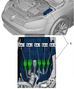
Fuse Box Location

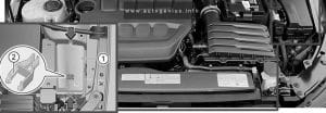
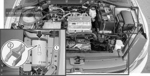
Volkswagen e-Golf (2014 - 2020) - fuse and relay box location - engine compartment
Volkswagen e-Golf (2014 – 2020) – fuse and relay box location – engine compartment

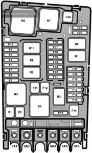
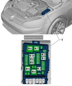
Fuse Box Diagram

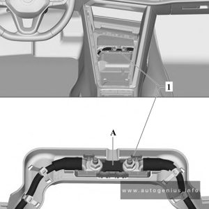
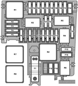
Volkswagen e-Golf (2014 - 2020) - fuse and relay box diagram - engine compartment
Volkswagen e-Golf (2014 – 2020) – fuse and relay box diagram – engine compartment


Assignment of the fuses in the engine compartment fuse box (-SA-, -SB-)

Amps Function / Component
SA1 125A Fuses (Instrument panel): 4, 5, 6, 7, 8, 9, 10, 11, 12, 13, 14, 31, 39, 41, 42, 53
Sockets relay
Power supply relay terminal 15
SA2 400A Electric drive power and control electronics
SA3 80A Power steering control module
SA4 80A Fuses (Instrument panel): 15, 16, 17, 18, 19, 20, 23, 24, 25, 26, 27, 43
SA5 50A Radiator fan
508 Battery Positive terminal
SB1 25A/40A ABS control module
SB2 40A ABS control module
– ABS hydraulic pump
SB3 15A Engine control module
SB4 5A Radiator fan
Radiator bypass switch-over valve
SB5
SB6
SB7 10A Radiator shutter motor
Water pump
Coolant pump in front of high-voltage heater (PTC)
SB8
SB9
SB10
SB11 40A Brake booster
SB12
SB13 7.5A 2018-2020:
Brake booster
SB14 40A Windshield defogger relay
SB15 15A Horn relay
SB16 10A High-voltage battery charger 1
Electric drive power and control electronics
SB17 7.5A Motronic engine control module power supply relay
Engine control module
ABS control module
Windshield defogger relay
Terminal 15 load reduction relay (2014-2016)
SB18 5A Battery monitoring control module
SB19 30A Wiper motor control module
SB20 10A Alarm horn
SB21
SB22
SB23
SB24
SB25
SB26
SB27
SB28
SB29
SB30
SB31
SB32
SB33 30A Brake system pressure reservoir
SB34 5A 2014-2018:
Brake booster
SB35 7.5A A/C relay
Thermal management control module
SB36
SB37
SB38
Relays
R1
R2
R3 Horn
R4 Brake Booster Vacuum Sensor link
R5 Main relay
R6 2014-2016:
Terminal 15 load reduction
R7
R8 A/C relay
R11 Windshield defogger

WARNING: Terminal and harness assignments for individual connectors will vary depending on vehicle equipment level, model, and market.

Volkswagen Golf VIII (mk8; 2020 – 2024) – fuse and relay box diagram

Volkswagen Golf VIII (MK8; 2020 – 2024) – fuse and relay box diagram


Year of production: 2020, 2021, 2022, 2023, 2024


This article provides the eighth-generation Volkswagen Golf (MK8), produced from 2020 to the present. It provides fuse box diagrams for the Volkswagen Golf VIII models from 2020, 2021, and 2022, along with details on the location of the fuse panels within the vehicle. Additionally, it explains the fuse and relay assignments (fuse layout).


Passenger Compartment Fuse Box (Fuse Panel C -SC-)

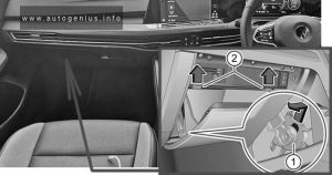
Fuse Box Location

Left-hand drive 

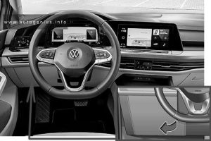
Volkswagen Golf (MK8; 2020 - 2022) - fuse and relay box location - passenger compartment (LHD)
Volkswagen Golf (MK8; 2020 – 2024) – fuse and relay box location – passenger compartment (LHD)


Right-hand drive 

Volkswagen Golf (MK8; 2020 - 2024) - fuse and relay box location - passenger compartment (RHD)
Volkswagen Golf (MK8; 2020 – 2024) – fuse and relay box location – passenger compartment (RHD)


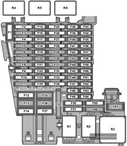
Fuse Box Diagram

Volkswagen Golf (MK8; 2020 - 2022) - fuse and relay box diagram - passenger compartment
Volkswagen Golf (MK8; 2020 – 2024) – fuse and relay box diagram – passenger compartment
Assignment of the fuses in the passenger compartment (instrument panel)
Amps Function / component
SC1
SC2
SC3 25 A Trailer detector control unit
SC4 20 A Control unit for reducing agent heater (diesel)
SC5 25 A Parking lock actuator
SC6 30 A Onboard supply control unit
Interior lighting
SC7 30 A Heater and air conditioning system control unit
Seat heating
SC8 20 A Sliding sunroof adjustment control unit
SC9 30 A Driver door control unit (left-hand drive models)
Front passenger door control unit (right-hand drive models)
Rear driver side window regulator motor (left-hand drive models)
Rear passenger side window regulator motor (right-hand drive models)
SC10
SC11 15 A Trailer detector control unit
SC12 40 A Onboard supply control unit
Exterior lighting (left-side)
SC13 40 A Onboard supply control unit
Central locking
SC14 30 A Digital sound package control unit
SC15
SC16 7.5 A Airbag control unit
SC17 10 A Relay for reducing agent metering system
SC18 7.5 A Interface for entry and start system
Driver exterior door handle (left-hand drive models)
Front passenger exterior door handle (right-hand drive models)
Control unit 2 for break-in protection
Control unit 3 for break-in protection
Control unit 4 for break-in protection
Control unit 5 for break-in protection
Control unit for electronic steering column lock
SC19 7.5 A Dash panel insert
Emergency call module control unit and communication unit
SC20 7.5 A Internet access control unit
Chip card reader control unit (Japan)
TV tuner (Japan)
Telephone bracket
Transmission and reception stabilisation control unit
USB connection 1
SC21 7.5 A Lane change assist control unit
Lane change assist control unit 2
Driver side exterior mirror
Passenger side exterior mirror
Rear lid handle
SC22
SC23
SC24 15 A All-wheel drive control unit
SC25 25 A Front left seat belt (left-hand drive models)
Front right seat belt (right-hand drive models)
SC26 30 A Driver door control unit (right-hand drive models)
Front passenger door control unit (left-hand drive models)
Rear driver side window regulator motor (right-hand drive models)
Rear passenger side window regulator motor (left-hand drive models)
SC27 25 A Front right seat belt (left-hand drive models)
Front left seat belt (right-hand drive models)
SC28
SC29 15 A Trailer detector control unit
SC30 30 A Control unit 1 for information electronics
SC31 25 A Trailer detector control unit
SC32 25 A Operating and display unit for rear air conditioning system
Rear seat heating
SC33
SC34
SC35 40 A Onboard supply control unit
Exterior lighting (right-side)
SC36 40 A Fresh air blower control unit
SC37
SC38
SC39 10 A Steering column electronics control unit
SC40 7.5 A Alarm horn
SC41 7.5 A Data bus diagnostic interface
SC42 7.5 A Selector mechanism
Selector lever position display
SC43 10 A Vehicle interior temperature sensor
Remote control receiver for auxiliary heater
Heater and air conditioning system control unit
Operating and display unit for rear air conditioning system
Heated rear window relay
SC44 7.5 A Parking brake button
Diagnostic connection
Front roof module
Anti-theft alarm sensor
Operating unit for lighting
Control unit for cornering light and headlight range control
Air humidity, rain and light sensor
SC45 7.5 A Steering column electronics control unit
SC46 7.5 A Control unit for Head-up Display
Display unit for front information display and operating unit control unit
SC47 10 A Electronically controlled damping control unit
SC48 7.5 A USB charging socket 1
SC49
SC50
SC51
SC52 20 A 12V socket
12V socket 3
SC53
SC54
SC55
SC56
SC57
SC58 7.5 A Front camera for driver assist systems
Parking aid control unit
Adaptive cruise control unit
SC59 7.5 A Parking brake button
Automatic anti-dazzle interior mirror
Air quality sensor
Pressure sender for refrigerant circuit
Reversing light switch
Relay for power sockets
Control unit for structure-borne sound
SC60 7.5 A Diagnostic connection
SC61 7.5 A Starter relay 1
Starter relay 2
SC62
SC63
SC64
SC65 10 A Engine sound generator control unit
SC66 15 A Rear window wiper motor
SC67 30 A Heated rear window relay
R1 Relay for power sockets
R2 Terminal 15 voltage supply relay
R3 Heated rear window relay
R4 Relay for reducing agent metering system (Diesel)
R5
R6

Individual fuses

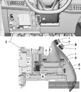
Left-hand drive models, from July 2020
Fuse Box Location and Diagram
Volkswagen Golf (MK8; 2020 - 2022) - fuse and relay box diagram - passenger compartment (individual fuses)
Volkswagen Golf (MK8; 2020 – 2024) – fuse and relay box diagram – passenger compartment (individual fuses) – LHD


Anps Function / component
A
B
C
D
E
F
G
H
I 15 A Driver seat adjustment control unit
Driver seat backrest fan
Driver seat cushion fan
J 15 A Front passenger seat backrest fan
Front passenger seat cushion fan

Left-hand drive models, from February 2021

Fuse Box Location and Diagram
Volkswagen Golf (MK8; 2020 - 2022) - fuse and relay box diagram - passenger compartment (individual fuses)
Volkswagen Golf (MK8; 2020 – 2024) – fuse and relay box diagram – passenger compartment (individual fuses) – LHD


Amps Function / component
A 15 A Driver seat adjustment control unit
B
C
D 15 A Driver seat backrest fan
Driver seat cushion fan
Operating unit for front left seat adjustment
E 15 A Front passenger seat backrest fan
Front passenger seat cushion fan
Operating unit for front right seat adjustment
F
H
G 10 A Special vehicle control unit
Diagnostic connection 2
Coupling point for wheelchair lift
Coupling point for two-way radio in special vehicle
Coupling point for front right door
Coupling point for front left door
Coupling point for accident data recorder
Coupling point for operating unit for special signals
I
J
K 40 A Coupling point for wheelchair lift
Special vehicle control unit
L 40 A Special vehicle control unit
Fuse 16 on relay and fuse carrier SRSH
M
N
O
P

Right-hand drive models, from July 2020

Fuse Box Location and Diagram
Volkswagen Golf (MK8; 2020 - 2022) - fuse and relay box diagram - passenger compartment (individual fuses) - RHD
Volkswagen Golf (MK8; 2020 – 2024) – fuse and relay box diagram – passenger compartment (individual fuses) – RHD
Amps Function / component
A
B
C
D
E
F
G
H
I
J
K
L
M 15 A Front passenger seat backrest fan
Front passenger seat cushion fan
N 15 A Driver seat adjustment control unit
Driver seat backrest fan
Driver seat cushion fan

Fitting location of fuse for voltage converter

Fuse Box Location and Diagram
Volkswagen Golf (MK8; 2020 - 2022) - fuse and relay box diagram - passenger compartment (individual fuses) - RHD
Volkswagen Golf (MK8; 2020 – 2024) – fuse and relay box diagram – passenger compartment (individual fuses) – RHD
Amps Function / component
A 125 A Battery, 48 V
Voltage converter (48 V/12V)

Engine Compartment Fuse Box

Fuse Box Location

Volkswagen Golf (MK8; 2020 - 2022) - fuse and relay box location - engine compartment
Volkswagen Golf (MK8; 2020 – 2024) – fuse and relay box location – engine compartment

Fuse Box Diagram (Fuse holder B -SB-)

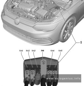
Volkswagen Golf (MK8; 2020 - 2022) - fuse and relay box location - engine compartment (fuse holder B -SB-)
Volkswagen Golf (MK8; 2020 – 2024) – fuse and relay box location – engine compartment (fuse holder B -SB-)


Assignment of the fuses in the engine compartment fuse box

Amps Function / component
SB1 400 A Power steering control unit
SB2 7.5 A Main relay (petrol)
Terminal 30 voltage supply relay (diesel)
Engine/motor control unit
ABS control unit
SB3 20 A Engine component current supply relay (2.0l petrol)
SB3 7.5 A Relay for gas shut-off valves (natural gas engine)
SB4 15 A Front left headlight
SB5 15 A Front right headlight
SB6
SB7 30 A Auxiliary hydraulic pump 1 for gearbox oil
SB8 40 A Brake servo
SB9 15 A Horn relay
SB10 30 A Wiper motor control unit
SB11
SB12 15 A / 30 A Mechatronic unit for dual clutch gearbox
Automatic gearbox control unit
SB13 25 A ABS control unit
SB14 20 A Auxiliary heater control unit
SB15 40 A ABS control unit
SB16
SB17 40 A Auxiliary air heater element (diesel)
SB18 40 A Auxiliary air heater element (diesel)
SB19
SB20 15 A Axle differential lock control unit
SB21 7.5 A Engine/motor control unit
SB22 30 A Starter
SB23 15 A Engine/motor control unit
SB24 7.5 A / 10 A Radiator fan
Oil level and oil temperature sender
Activated charcoal filter solenoid valve 1 (petrol, natural gas engine)
Exhaust camshaft control valve 1 (petrol, natural gas engine)
Inlet camshaft control valve 1 (petrol, natural gas engine)
Valve for oil pressure control (petrol, natural gas engine)
Piston cooling jet control valve (petrol, natural gas engine)
Fuel pressure regulating valve (diesel)
Relay for reducing agent metering system (diesel)
Automatic glow period control unit (diesel)
Starter-alternator (models with 48 V system)
Inlet cam actuator for cylinder 2 (1.5l petrol)
Exhaust cam actuator for cylinder 2 (1.5l petrol)
Inlet cam actuator for cylinder 3 (1.5l petrol)
Exhaust cam actuator for cylinder 3 (1.5l petrol)
Gas tank pressure sensor (natural gas engine)
Relay for gas shut-off valves (natural gas engine)
SB25 10 A Gas injection valve 1 (natural gas engine)
Gas injection valve 2 (natural gas engine)
Gas injection valve 3 (natural gas engine)
Gas injection valve 4 (natural gas engine)
SB26 10 A Heater element for crankcase breather (diesel)
Valve for oil pressure control (diesel)
Actuator for engine temperature regulation (diesel)
Coolant regulating valve (diesel)
Piston cooling jet control valve (diesel)
Coolant circulation pump (2.0l petrol)
Charge air cooling pump (petrol, natural gas engine)
Auxiliary pump for heating (diesel)
SB27 10 A / 15 A Particulate sensor (diesel)
Lambda probe 1 after catalytic converter (petrol)
Lambda probe 1 before catalytic converter (petrol)
Control unit for NOx sender (diesel)
Control unit 2 for NOx sender (diesel)
Control unit 3 for NOx sender (diesel)
Control unit 1 for particulate sensor (diesel)
SB28 20 A Ignition coil 1 with output stage (1.5l petrol, 1.4l petrol)
Ignition coil 2 with output stage (1.5l petrol, 1.4l petrol)
Ignition coil 3 with output stage (1.5l petrol, 1.4l petrol)
Ignition coil 4 with output stage (1.5l petrol, 1.4l petrol)
Activated charcoal filter solenoid valve 1 (1.4l petrol)
Inlet camshaft control valve 1 (1.4l petrol)
Exhaust camshaft control valve 1 (1.4l petrol)
Valve for oil pressure control (1.4l petrol)
SB29 15 A / 20 A Fuel pump control unit
SB30
SB31
SB32
R1 Main relay
R2 High heat output relay (diesel)
R3 Horn relay
R4 Starter relay 1
R5 Starter relay 2
R6 Relay for gas shut-off valves (natural gas drive)
Engine component current supply relay (2.0l petrol engine)
R7 Automatic glow period control unit
R8 Low heat output relay

High Power Fuses (Fuse holder A -SA-)

Fuse Box Location and Diagram

Volkswagen Golf (MK8; 2020 - 2022) - fuse and relay box location - engine compartment (fuse holder A -SA-)
Volkswagen Golf (MK8; 2020 – 2024) – fuse and relay box location – engine compartment (fuse holder A -SA-)


Amps Function / component
SA1 150 A Fuse holder B
SA2 50 A Radiator fan
SA3
508 Battery
SA4 125 A Fuse holder C
SA5 125 A Fuse holder C

WARNING: Terminal and harness assignments for individual connectors will vary depending on vehicle equipment level, model, and market.
Volkswagen Golf VII (mk7; 2013 – 2020) – fuse and relay box diagram

Volkswagen Golf VII (mk7; 2013 – 2020) – fuse and relay box diagram

Year of production: 2013, 2014, 2015, 2016, 2017, 2018, 2019, 2020

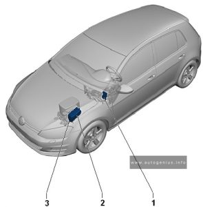
Overview of fuse holder

Volkswagen Golf VII (mk7; 2013 - 2020) - fuse and relay box location - overview of fuse holder
Volkswagen Golf VII (mk7; 2013 – 2020) – fuse and relay box location – overview of fuse holder
Description
1 Fuse panel C -SC-
2 Fuse panel B -SB-
3 Fuse panel A -SA-

Passenger Compartment Fuse Box

Fuse Box Diagram (Fuse Panel C- SC)

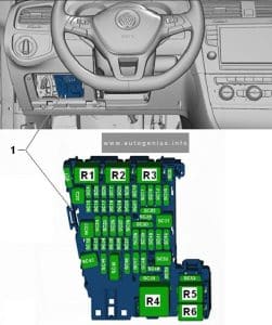
Volkswagen Golf VII (mk7; 2013 - 2020) - fuse and relay box location - passenger compartment (fuse panel c -sc-)
Volkswagen Golf VII (mk7; 2013 – 2020) – fuse and relay box location – passenger compartment (fuse panel C -SC-)


Fuse assignment fuse panel C -SC-

Designation in Wiring Diagram A Component Terminal
F1
F2
F3
F4 Fuse 4 on fuse panel C -SC4- 10 Vehicle electrical system control module -J519-,
Anti-theft alarm system
30
F5 Fuse 5 on fuse panel C -SC5- 5 Data bus on board diagnostic interface -J533- 30
F6 Fuse 6 on fuse panel C -SC6- 5 Anti-theft alarm system sensor -G578- 30
F7 Fuse 7 on fuse panel C -SC7- 10 Heater and A/C controls -EX21-
Heater control module -J65-
Climatronic control unit -J255-
A/C control module -J301-
Selector lever -E313-
Auxiliary engine coolant heater radio
frequency receiver -R149-
Rear window defogger relay -J9-
30
F8 Fuse 8 on fuse panel C -SC8- 10 Rotary light switch -EX1- 30
Electro-mechanical parking brake button -E538-
Humidity, rain and light recognition sensor -G823-
Diagnostic connection -U31-
30
F9
F10 Fuse 10 on fuse panel C -SC10- 10 Front information display control head -J685- 30
F11 Fuse 11 on fuse panel B -SB11- 15 All wheel drive control module -J492- 30
F12 Fuse 12 on fuse panel C -SC12- 20 Information electronics control module 1 -J794- 30
F13 Fuse 13 on fuse panel C -SC13- 15 Electronic damping control module -J250- 30
F14 Fuse 14 on fuse panel C -SC14- 30 Fresh air blower control module -J126- 30
F15 Fuse 15 on fuse panel C -SC15- 10 Electronic steering column lock control module
-J764-
30
F16 Fuse 16 on fuse panel C -SC16- 7,5 Mobile communication 2-way signal amplifier -J984-
Antenna amplifier 3 -R112-
Voltage converter for USB charge module -A5-
30
F17 Fuse 17 on fuse panel C -SC17- 5 Instrument cluster control module -J285-
Instrument cluster -KX2-
30
F18 Fuse 18 on fuse panel C -SC18- 7,5 Rearview camera -R189-
Rear lid unlock switch -E165-
30
F19 Fuse 19 on fuse panel C -SC19- 7,5 Access/start system interface -J965- 30
F20
F21
F22
F23 Fuse 23 on fuse panel C -SC23- 40 Vehicle electrical system control module -J519-
Right front headlamp -MX2-
30
F24 Fuse 24 on fuse panel C -SC24- 30 Power sunroof control module -J245- 30
F25 Fuse 25 on fuse panel C -SC25- 30 Driver door control module -J386- 1)
Left rear window regulator motor -V26- 1)
Front passenger door control module -J387- 2)
Right rear window regulator motor -V27- 2)
30
F26 Fuse 26 on fuse panel C -SC26- 20 Vehicle electrical system control module -J519-
Front heated seat
30
F27 Fuse 27 on fuse panel C -SC27- 30 Digital Sound System Control Module -J525- 30
F28 Fuse 28 on fuse panel C -SC28- 20 Towing recognition control module -J345- 30
F29
F30 Fuse 30 on fuse panel C -SC30- 25 Left front seat belt tensioner control module -J854- 30
F31 Fuse 31 on fuse panel C -SC31- 40 Vehicle electrical system control module -J519-
Left front headlamp -MX1-
30
F32 Fuse 32 on fuse panel C -SC32- 7,5 Driver assistance systems front camera -R242-
Distance regulation control module -J428-
Parking aid control module -J446-
Parallel parking assistance control module –
J791-
15
F33 Fuse 33 on fuse panel C -SC33- 5 Airbag control module -J234- 15
Front passenger airbag -disabled- indicator
lamp -K145-
F34 Fuse 34 on fuse panel C -SC34- 7,5 Rotary light switch -EX1-
Interior rearview mirror -EX5-
Tire pressure monitoring display button -E492-
Socket relay -J807-
Back-up lamp switch -F4-
Refrigerant circuit pressure sensor -G805-
Air quality sensor -G238-
Electro-mechanical parking brake button –
E538-
15
F15 Fuse 35 on fuse panel C -SC35- 10 Diagnostic connection -U31-
Headlamp range control and instrument
illumination regulator -EX14-
Automatic dimming interior rearview mirror -Y7

Cornering lamp and headlamp range control
module -J745-
Left headlamp beam adjustment motor -V48-
Right headlamp beam adjustment motor -V49-
15
F36 Fuse 36 on fuse panel C -SC36- 10 Right daytime running lamp and parking lamp
control module -J861-
15
F37 Fuse 37 on fuse panel C -SC37- 10 Left daytime running lamp and parking lamp
control module -J860-
15
F38 Fuse 38 on fuse panel C -SC38- 20 Towing recognition control module -J345- 30
F39 Fuse 39 on fuse panel C -SC39- 30 Front passenger door control module -J387-
Right rear window regulator motor -V27- 1)
Driver door control module -J386- 2)
Left rear window regulator motor -V26- 2)
30
F40 Fuse 40 on fuse panel C -SC40- 20 Cigarette lighter -U1-3)
12 V socket -U5-
12 V socket 2 -U18-
12 V socket 3 -U19-
15/30 4)
F41 Fuse 41 on fuse panel C -SC41- 10 Steering column electronics control module -J527- 30
F42 Fuse 42 on fuse panel C -SC42- 40 Vehicle electrical system control module -J519-
Central locking system
30
F43 Fuse 43 on fuse panel C -SC43- 30 Vehicle electrical system control module -J519- 30
F44 Fuse 44 on fuse panel C -SC44- 15 Towing recognition control module -J345- 30
F45 Fuse 45 on fuse panel C -SC45- 15 Driver seat lumbar support adjustment switch -E176-
Driver seat adjustment control head -E470-
Front passenger seat adjustment control head -E471-
Front passenger seat lumbar support adjustment switch -E177-
30
F46
F47 Fuse 47 on fuse panel C -SC47- 15 Rear window wiper motor -V12- 15
F48
F49 Fuse 49 on fuse panel C -SC49- 5 Clutch pedal position sensor -G162-
Starter relay 1 -J906-
Starter relay 2 -J907-
15
F50
F51 Fuse 51 on fuse panel C -SC51- 25 Right front seat belt tensioner control module -J855- 15
F52
F53
1) Only for left-hand drive vehicles
2) Only for right-hand drive vehicles
3) Smoking package
4) Depending on equipment

Engine Compartment Fuse Box

Fuse Box Diagram (Fuse Panel B- SB)

Volkswagen Golf VII (mk7; 2013 - 2020) - fuse and relay box location - engine compartment (fuse panel B -SB-)
Volkswagen Golf VII (mk7; 2013 – 2020) – fuse and relay box location – engine compartment (fuse panel B -SB-)


Fuse assignment fuse panel B -SB-

Designation in Wiring Diagram A Component Terminal
F1 Fuse 1 on fuse panel B -SB1- 40 ABS control module -J104- 30
F2 Fuse 2 on fuse panel B -SB2- 40 ABS control module -J104-
ABS hydraulic pump -V64-
30
F3 Fuse 3 on fuse panel B -SB3- 15 1) Engine control module -J623- 87
30 2)
F4 Fuse 4 on fuse panel B -SB4- 5 2) Oil level thermal sensor -G266- 87
Coolant fan control module -J293-
EVAP canister purge regulator valve 1 -N80- 1)
Camshaft adjustment valve 1 -N205-(1
Exhaust camshaft adjustment valve 1 -N318- 1)
Oil pressure regulation valve -N428- 1)
High heat output relay -J360-2)
EGR cooler switch-over valve -N345- 2)
Low heat output relay -J359- 2)
Wastegate bypass regulator valve -N75- 2)
Cylinder 2 intake camshaft adjuster -N583- 1)
Cylinder 2 exhaust camshaft adjuster -N587- 1)
Cylinder 3 intake camshaft adjuster -N591- 1)
Cylinder 3 exhaust camshaft adjuster -N595- 1)
Ethanol concentration sensor -G708- 1)
87
10 1)
F5 Fuse 5 on fuse panel B -SB5- 10 2) Fuel pressure regulator valve -N276-
Fuel metering valve -N290-
87
F6 Fuse 6 on fuse panel B -SB6- 5 Brake lamp switch -F- 87
F7 Fuse 7 on fuse panel B -SB7- 7,5 1) Fuel pressure regulator valve -N276-1)
Charge air cooling pump -V188-1)
Oil pressure regulation valve -N428-2)
Cooling circuit solenoid valve -N492-2)
Charge air cooling pump -V188-2)
Heater support pump -V488- 2)
87
10 2)
F8 Fuse 8 on fuse panel B -SB8- 10 1) Oxygen sensor heater -Z19-
Oxygen sensor 1 before catalytic converter -GX10-
Heater for oxygen sensor 1 after catalytic converter -Z29-
Oxygen sensor 1 after catalytic converter -GX7-
Mass airflow sensor -G70-
87
F9 Fuse 9 on fuse panel B -SB9- 5 2) Ignition coil 1 with power output stage -N70- 1)
Ignition coil 2 with power output stage -N127-1)
Ignition coil 3 with power output stage -N291-
1)
Ignition coil 4 with power output stage -N292-1)
Automatic glow time control module -J179- 2)
Early fuel evaporation heating element -N51- 2)
87
20 1)
F10 Fuse 10 on fuse panel B -SB10- 15 1) Fuel pump control module -J538- 87
20 2)
F11 Fuse 11 on fuse panel B -SB11- 40 Auxiliary heater heating element -Z35- 87
F12 Fuse 12 on fuse panel B -SB12- 40 Auxiliary heater heating element -Z35- 87
F13 Fuse 13 on fuse panel B -SB13- 30 DSG transmission Mechatronic -J743- 30
F14
F15 Fuse 15 on fuse panel B -SB15- 15 Horn relay -J413- 30
F16
F17 Fuse 17 on fuse panel B -SB17- 7,5 Motronic engine control module power supply
relay -J271- 1)
Terminal 30 power supply relay -J317-2)
Engine control module -J623-
ABS control module -J104-
30
F18 Fuse 18 on fuse panel B -SB18- 5 Battery monitoring control module -J367-
Data bus on board diagnostic interface -J533-
3)
30
F19 Fuse 19 on fuse panel B -SB19- 30 Wiper motor control module -J400- 30
F20 Fuse 20 on fuse panel B -SB20- 20 Anti-theft alarm system horn -H8- 30
F21
F22 Fuse 22 on fuse panel B -SB22- 5 Engine control module -J623- 50
F23 Fuse 23 on fuse panel B -SB23- 30 Starter -B- 50
F24 Fuse 24 on fuse panel B -SB24- 40 Auxiliary heater heating element -Z35- 87
F25
F26
F27
F28
F29
F30
F31
F32
F33
F34
F35
F36
F37 Fuse 37 on fuse panel B -SB37- 20 Auxiliary heater control module -J364- 30
F38
1) Only for vehicles with gasoline engine
2) only for vehicles with a diesel engine
3) Only for vehicles without Stop/Start

Engine Compartment Fuse Box

Fuse Box Diagram (Fuse Panel A- SA)

Volkswagen Golf VII (mk7; 2013 - 2020) - fuse and relay box location - engine compartment (fuse panel A -SA-)
Volkswagen Golf VII (mk7; 2013 – 2020) – fuse and relay box location – engine compartment (fuse panel A -SA-)


Fuse assignment fuse panel A -SA-

Designation in Wiring Diagram A Component Terminal
J Fuse 1 on fuse panel A -SA1- 100 Fuses Supply:
-SC4- …-SC14-
-SC30-
-SC31-
-SC38-
-SC39-
-SC41-
-SC42-
-SC53-
Front passenger power seat adjustment
circuit breaker 1 -S46-
Terminal 15 power supply relay -J329-
30
G1 Fuse 2 on fuse panel A -SA2- 100 1) Generator -C- 30
200 2)
250 3)
E1 Fuse 3 on fuse panel A -SA3- 80 Power steering control module -J500- 30
K1 Fuse 4 on fuse panel A -SA4- 80 Fuses Supply:
-SC15- …-SC20-
-SC23- …-SC28-
-SB43- …-SB45-
30
L1 Fuse 5 on fuse panel A -SA5- 80 Coolant fan -VX57- 30
1) Only for vehicles with a 90 A generator
2) Only for vehicles with a 140 A generator
3) Only for vehicles with a 180 A generator

WARNING: Terminal and harness assignments for individual connectors will vary depending on vehicle equipment level, model, and market.
Volkswagen Golf 3(1991 – 1997) – fuse box diagram

Volkswagen Golf mk3 (1991 – 1997) – fuse box diagram

Year of production: 19991, 1992, 1993, 1994, 1995, 1996, 1997


The 3rd generation Volkswagen Golf compact car was produced in 1991, 1992, 1993, 1994, 1995, 1996, 1997, 1998, 1999, 2000, 2001 and 2002 with gasoline and diesel engines. Delivered worldwide in various body styles: convertible, sedan, station wagon and hatchback. In this article you will find a designation of the fuse and relay boxes diagram of the 3rd generation Volkswagen Golf.

Passenger compartment

Fuse box location

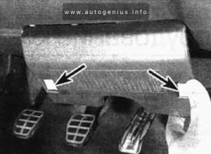
It is located at the bottom of the dashboard on the driver’s side, behind the protective cover. To remove it, press the buttons – latches.

Volkswagen Golf 3 - fuse box location - passenger compartment 
Volkswagen Golf 3 – fuse box location – passenger compartment 

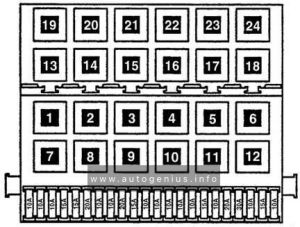
Fuse box diagram

Volkswagen Golf 3 - fuse box location - passenger compartment
Volkswagen Golf 3 – fuse box location – passenger compartment

A
Circuits protected
1 10 Headlight, low beam, left
2 10 Headlight, low beam, right
3 10 Instrument and number plate lighting
4 15 Rear window wiper and washer system, sliding/tilting roof
5 15 Windscreen wiper, windscreen and rear window washer, electric heated windscreen washer jets
6 20 Fresh air blower, A/C
6 30 Blower, air conditioner
7 10 Tail lights, right
8 10 Tail lights, left
9 15 Rear window defogger
9 20 Rear window heating, mirror heating
10 15 Fog lights, rear fog light
11 10 Headlight, high beam, left. main beam warning lamp
12 10 Headlight, high beam, right
13 10 Horn, radiator fan (run-on)
14 10 Back-up fights
14 15 Reversing lights, electric outside mirrors, seat heating, elec. windows, air conditioner cruise control system
15 10 Engine electronics, coolant circulation run-on pump, (six cylinder engine)
16 15 Warning lamps, glove box light, cassette storage box light, power sunroof, front map/reading light
17 10 Emergency flashers
18 20 Fuel pump (FP), heated oxygen sensor (H02S) control module
19 30 Coolant fan, A/С relay
20 10 Brake lights, cruise control system (trigger contacts on brake and clutch pedals)
21 15 Interior and luggage compartment lights, clock, cigarette lighter, central locking, multi-function indicator
22 10 Cigarette fighter, radio, luggage compartment

Relay


Circuits protected
1 Air conditioner relay
2 Rear window wiper / washer relay
3 Relay, electronic engine control unit
4 Relay for main ignition circuits
5
6 Relay – turn signal interrupter
7 Headlight washer control unit
8 Relay for intermittent operation of the windshield wiper / washer
9 Seat belt not fastened indicator relay 1995
10 Fog lamp relay
11 Horn relay
12 Fuel pump relay
13 Intake manifold heater relay
14
15 Pump relay ABS
16 Reversing light relay (Ecomatic)
17 Headlamp High Beam Relay (Ecomatic)
18 Low beam relay (Ecomatic)
19 Fuse 30A – air conditioning, Climatronic 2.0 / 2.8 (1993)
20 Start inhibit switch relay
21 Oxygen sensor relay
22 Seat Belt Not Fastened Indicator Relay (1995)
23 Vacuum pump relay (Ecomatic)
24 Thermal fuse (20A) – Power windows

Additional fuses (in separate holders, above the relays)


A
Circuits protected
1 30 Fuse for ABS motor relay
2 30 Fuse for ABS main relay
3 10 Fuse for normal air conditioner
4 30 Fuse for fresh air blower on Climatronic
5 5 Fuse for Climatronic
6 20 Automatic fuse for electric windows
7 15 Trailer perma nent +

Additional fuses (in the engine compartment on the bulkhead above the brake servo)

On vehicles with diesel engines, the glow plug power supply circuit is protected by a high power fuse in the form of a fusible link.

Volkswagen Golf 3 - fuse box location - engine compartment
Volkswagen Golf 3 – fuse box location – engine compartment

A
Circuits protected
1 50 Diesel glow plugs

WARNING: Terminal and harness assignments for individual connectors will vary depending on vehicle equipment level, model, and market.