Holden Trax (TJ; 2017 – 2020) – fuse and relay box diagram
Year of production: 2017, 2018, 2019, 2020
This article provides the first-generation Holden Trax (TJ, facelifted) produced between 2017 and 2020. It provides fuse box diagrams for the 2017, 2018, 2019, and 2020 models, along with details on the location of the fuse panels within the vehicle and the specific functions of each fuse and relay (fuse layout).
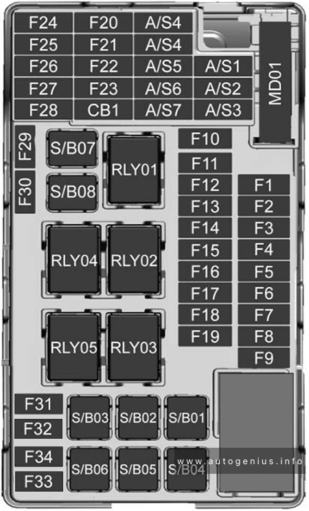
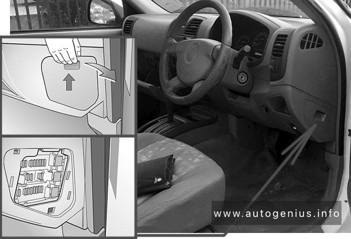
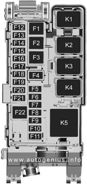
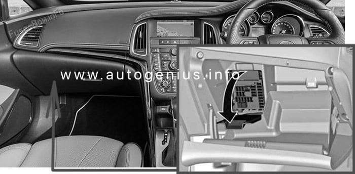
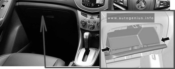
Passenger Compartment Fuse Box
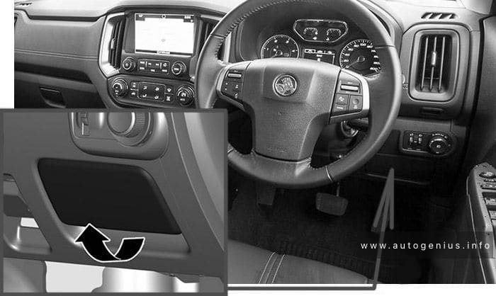
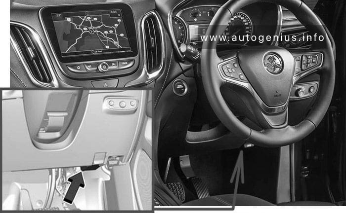
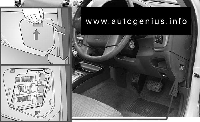
Fuse Box Location
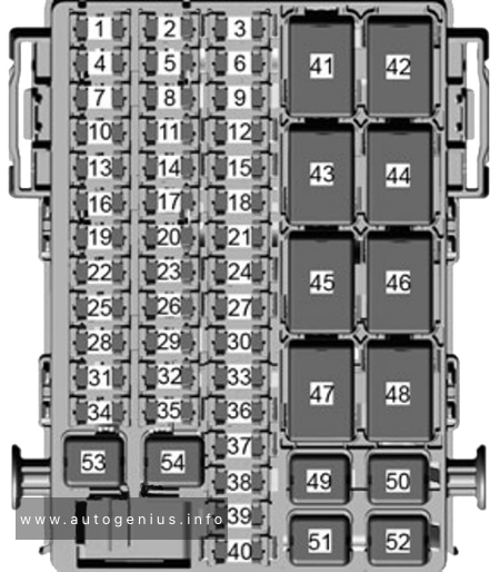
The interior fuse block is located in the glove box.
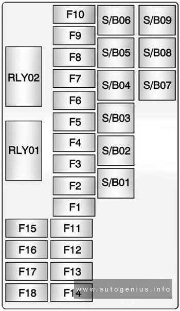
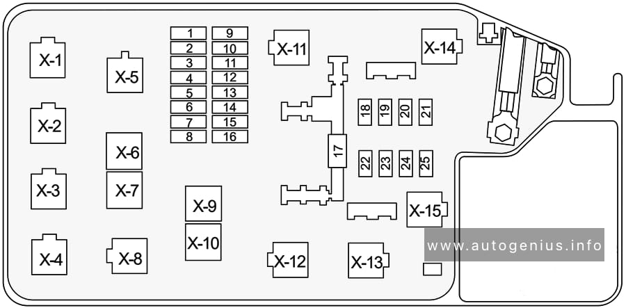
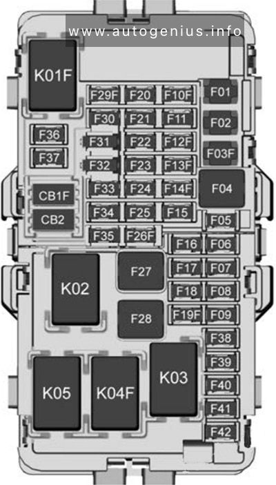
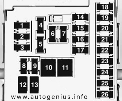
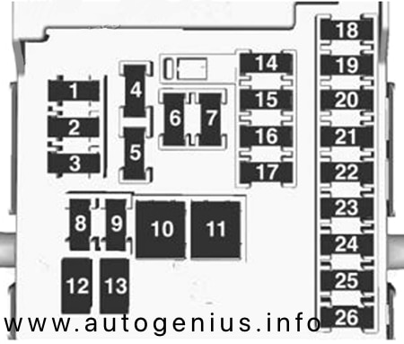
Fuse Box Diagram
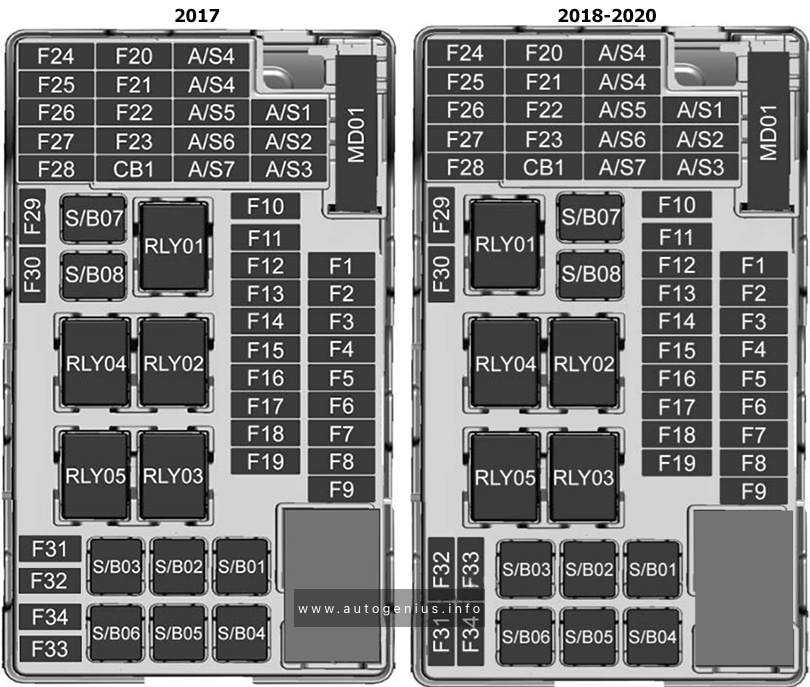
Assignment of the fuses in the passenger compartment
| № | Description |
|---|---|
| F1 | BCM 1 |
| F2 | BCM 2 |
| F3 | BCM 3 |
| F4 | BCM 4 |
| F5 | BCM 5 |
| F6 | BCM 6 |
| F7 | BCM 7 |
| F8 | BCM 8 |
| F9 | DLIS |
| F10 | SDM B+ |
| F11 | DLC |
| F12 | HVAC MDL |
| F13 | L/GATE RLY |
| F14 | CGM |
| F15 | 2018-2020: LDW Gentex |
| F16 | – |
| F17 | ESCL B+ |
| F18 | 2017: UPA B+ / SBZA BT 2018-2020: PAS / SBZA |
| F19 | BCM RVC |
| F20 | Clock Spring |
| F21 | 2017: AC APO 2018-2020: APO AC / PRNDL |
| F22 | 2017: DC APO 2018-2020: APO DC FRT |
| F23 | – |
| F24 | – |
| F25 | 2018: OnStar |
| F26 | 2018: EVP |
| F27 | 2017: IPC 2018-2020: IPC PTC RLAD |
| F28 | 2018-2020: TRLR Feed2 |
| F29 | – |
| F30 | – |
| F31 | IPC B+ |
| F32 | Audio / Nav |
| F33 | 2018-2020: TRLR Feed1 |
| F34 | PEPS Module |
| S/B01 | 2018-2020: PTC 1 |
| S/B02 | 2018-2020: PTC 2 |
| S/B03 | PWR WNDW MTR FRT |
| S/B04 | PWR WNDW REAR |
| S/B05 | Logistic Mode RLY |
| S/B06 | 2018-2020: PWR Seat DR |
| S/B07 | – |
| S/B08 | Trailer Interface Module |
| Relays | |
| RLY1 | ACC/RAP |
| RLY2 | L/GATE |
| RLY3 | – |
| RLY4 | Blower |
| RLY5 | Logistic Mode |
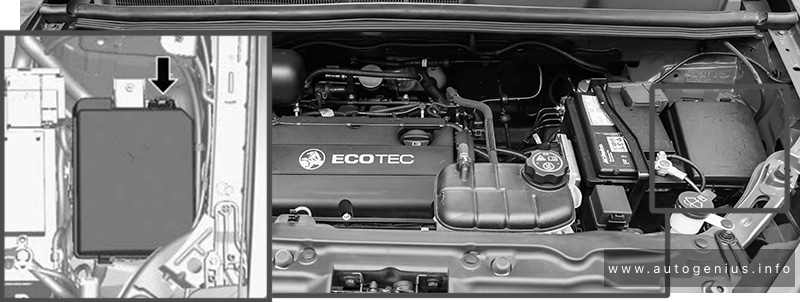
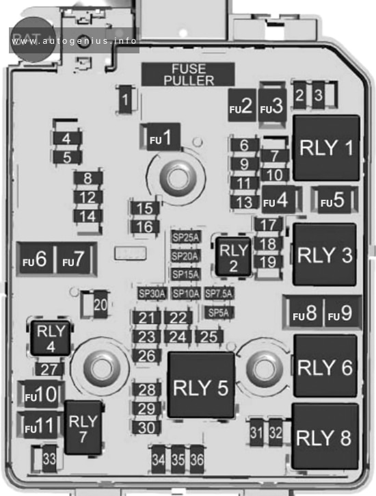
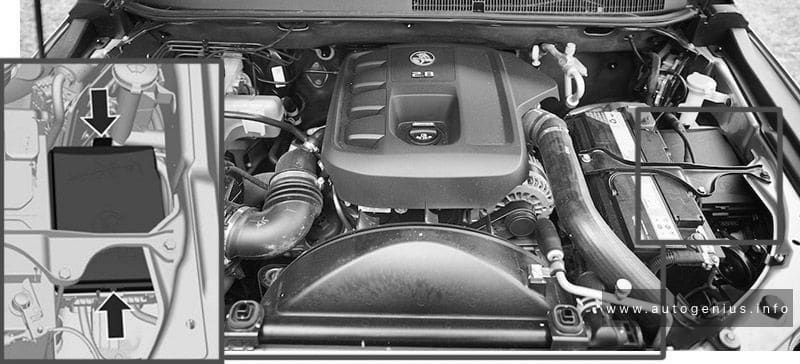
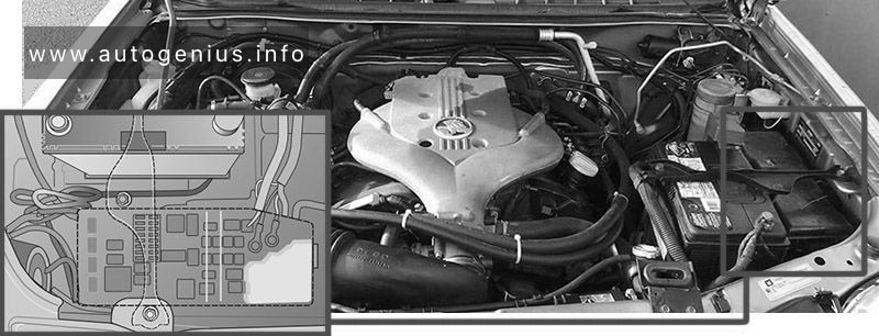
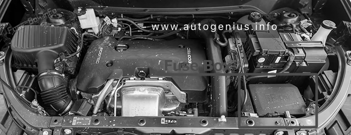
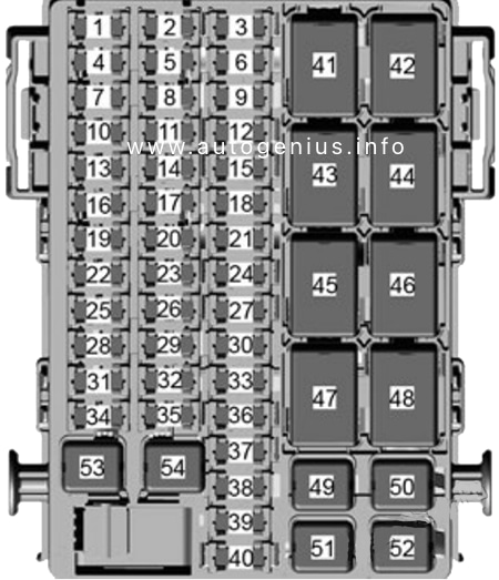
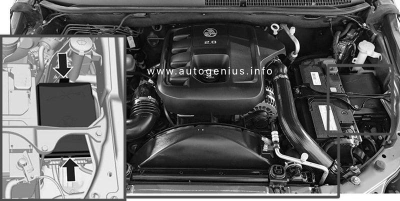
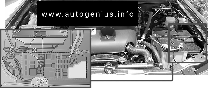
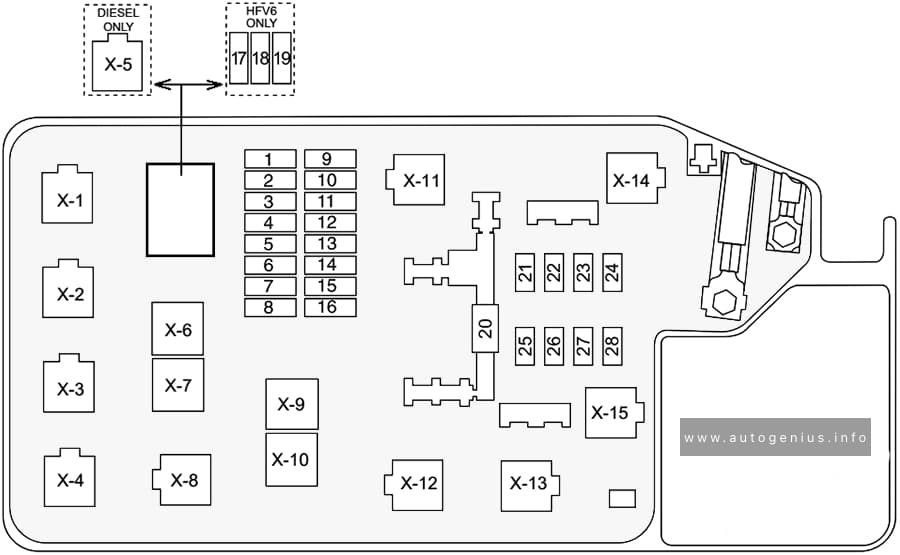
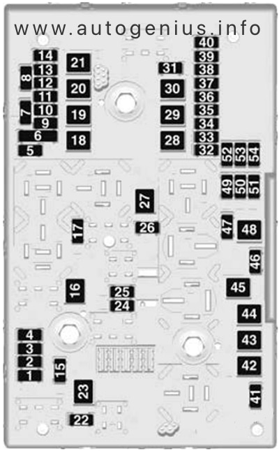
Engine Compartment Fuse Box
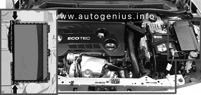
Fuse Box Location

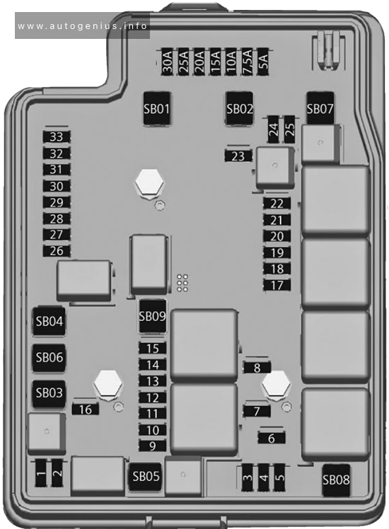
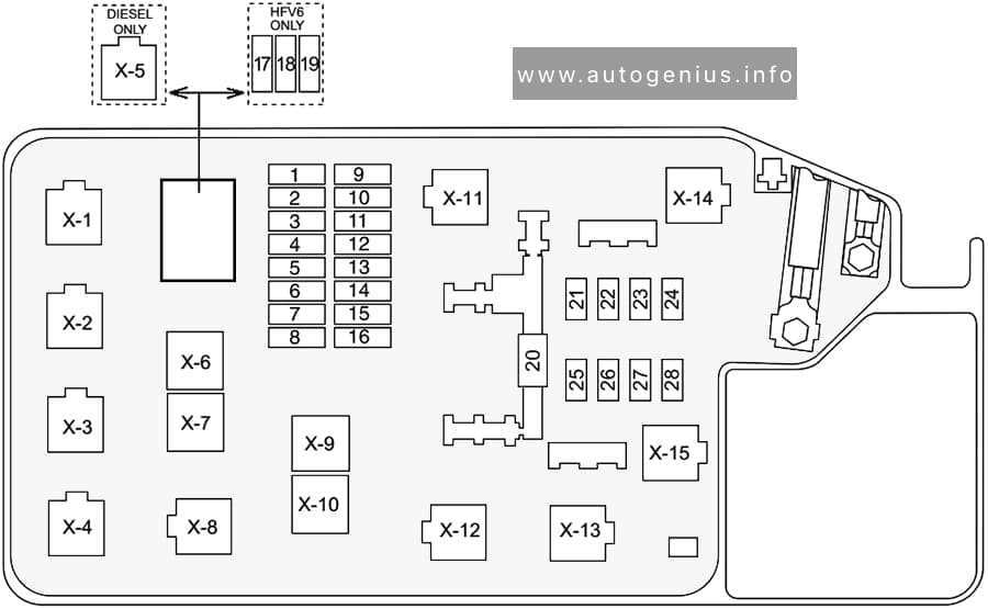
Fuse Box Diagram

Assignment of the fuses in the engine compartment
| № | Description |
|---|---|
| F1 | Sunroof |
| F2 | OSRVM SW, Rain Sensor, PWR Window Driver |
| F3 | – |
| F4 | – |
| F5 | EBCM Valve |
| F6 | – |
| F7 | ESCL |
| F8 | TCM B+ |
| F9 | – |
| F10 | HDLP Leveling SW, HDLP Leveling MTR LH/RH, Rear Vision Camera ISRVM |
| F11 | Rear Wiper |
| F12 | RR WDW Defog |
| F13 | – |
| F14 | OSRVM Heat |
| F15 | – |
| F16 | Heated Seat Module |
| F17 | 2017: Compass Module, TIM R/C 2018: Compass Module, TIM DC/DC Converter FSCM R/C 2019-2020: TIM |
| F18 | ECM R/C, TCM R/C, FICM R/C |
| F19 | Fuel Pump |
| F20 | – |
| F21 | Fan RLY (AUX BEC) |
| F22 | – |
| F23 | Ignition Coil, Injector Coil |
| F24 | Washer Pump |
| F25 | – |
| F26 | 2017: Canister Purge SOL, Water Valve SOL, Turbo Wastegate SOL, Turbo Bypass SOL, O2 Sensor Pre/Post 2018-2020: EMS Var-1 |
| F27 | – |
| F28 | – |
| F29 | ECM PT IGN-1, IGN-2 |
| F30 | 2017: MAF Sensor 2018-2020: EMS Var-2 |
| F31 | High Beam LH |
| F32 | High Beam RH |
| F33 | ECM B+ |
| F34 | Horn |
| F35 | A/C Clutch |
| F36 | Front Fog Lamp |
| FU1 | EBCM Pump |
| FU2 | FRT Wiper |
| FU3 | Blower |
| FU4 | IEC R/C |
| FU5 | – |
| FU6 | – |
| FU7 | – |
| FU8 | Cooling Fan Low/Mid |
| FU9 | Cooling Fan High |
| FU10 | EVP |
| FU11 | Starter SOL |
| SP | Spare Fuses |
| Relays | |
| 1 | Run Crank |
| 2 | Fuel Pump |
| 3 | 2018-2020: Cooling Fan Mid |
| 4 | – |
| 5 | PT Relay |
| 6 | Cooling Fan High |
| 7 | Starter |
| 8 | Cooling Fan Low |
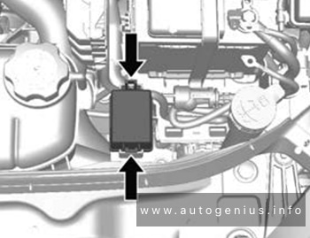
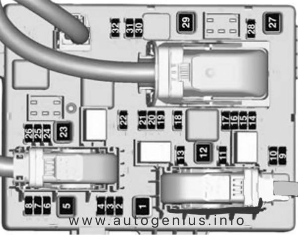
Auxiliary relay box
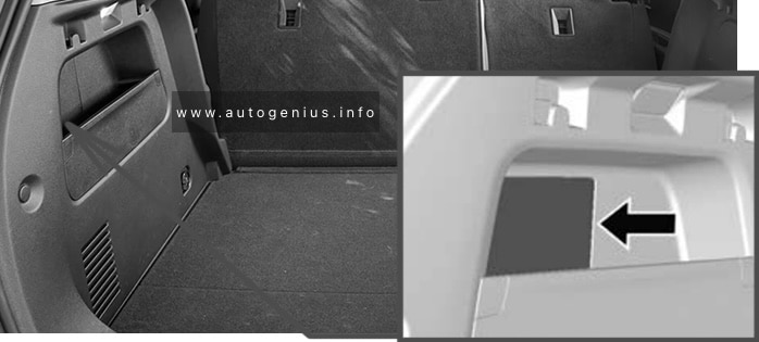
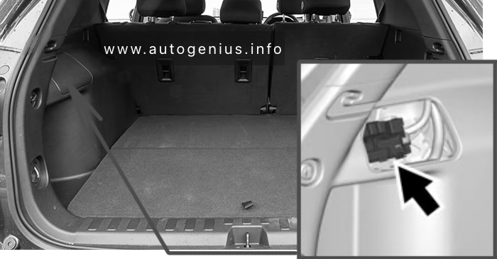
Relay Box Location
The rear compartment fuse box is located in the passenger side of the rear compartment.

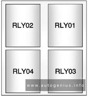
Relay Box Diagram

Assignment of the fuses in the auxiliary relay box
| № | Relays |
|---|---|
| RLY01 | ELECTRIC VACUUM PUMP |
| RLY02 | COOLING FAN 1 |
| RLY03 | COOLING FAN 2 |
| RLY04 | – |
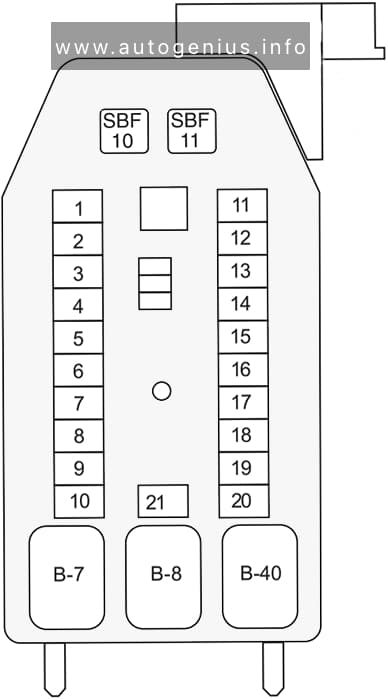
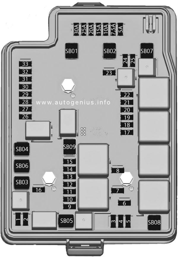
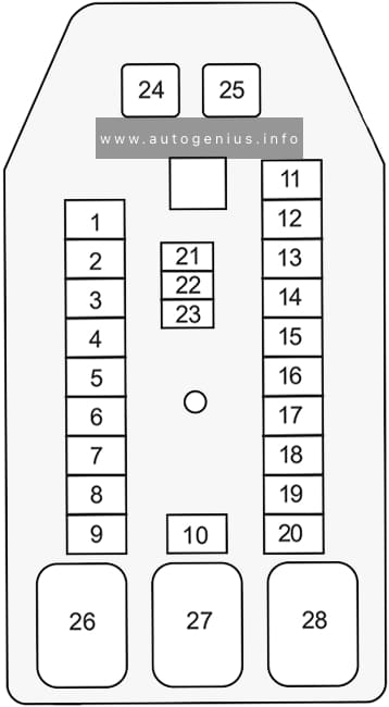
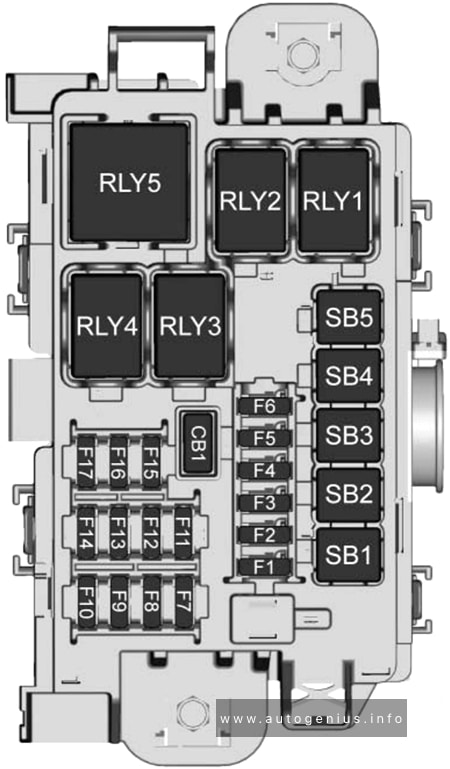
Rear Compartment Fuse Box
Fuse Box Location
The rear compartment fuse box is located in the passenger side of the rear compartment.

Fuse Box Diagram (2017)

Assignment of the fuses in the rear compartment (2017)
| № | Description |
|---|---|
| F1 | – |
| F2 | – |
| F3 | – |
| F4 | – |
| F5 | – |
| F6 | – |
| F7 | – |
| F8 | – |
| F9 | – |
| F10 | – |
| F11 | – |
| F12 | – |
| F13 | – |
| F14 | – |
| F15 | – |
| F16 | – |
| F17 | Spare |
| F18 | – |
| S/B01 | – |
| S/B02 | – |
| S/B03 | – |
| S/B04 | AC DC INV |
| S/B05 | – |
| S/B06 | – |
| S/B07 | – |
| S/B08 | – |
| Relays | |
| RLY1 | – |
| RLY2 | – |
Fuse Box Diagram (2018 – 2020)
Assignment of the fuses in the rear compartment (2018 – 2020)
| № | Description |
|---|---|
| F1 | 2018: Amplifier |
| F2 | 2018: RDCM |
| F3 | – |
| F4 | 2018: NOX Soot |
| F5 | 2018: NOX Soot/Heater Pipe |
| F6 | 2018: SCRPM |
| F7 | 2018: SCRPM |
| F8 | – |
| F9 | – |
| F10 | – |
| F11 | – |
| F12 | – |
| F13 | – |
| F14 | – |
| F15 | – |
| F16 | – |
| F17 | – |
| SB1 | 2018: DC/DC |
| SB2 | 2018: DC/DC |
| SB3 | DC/AC Inverter |
| SB4 | 2018: NOX Heater Pipe |
| SB5 | – |
| Relays | |
| RLY1 | – |
| RLY2 | – |
| RLY3 | 2018: ECM/NOX Soot |
| RLY4 | 2018: ECM/NOX Heater Pipe |
| RLY5 | – |
WARNING: Terminal and harness assignments for individual connectors will vary depending on vehicle equipment level, model, and market.